 flow
flow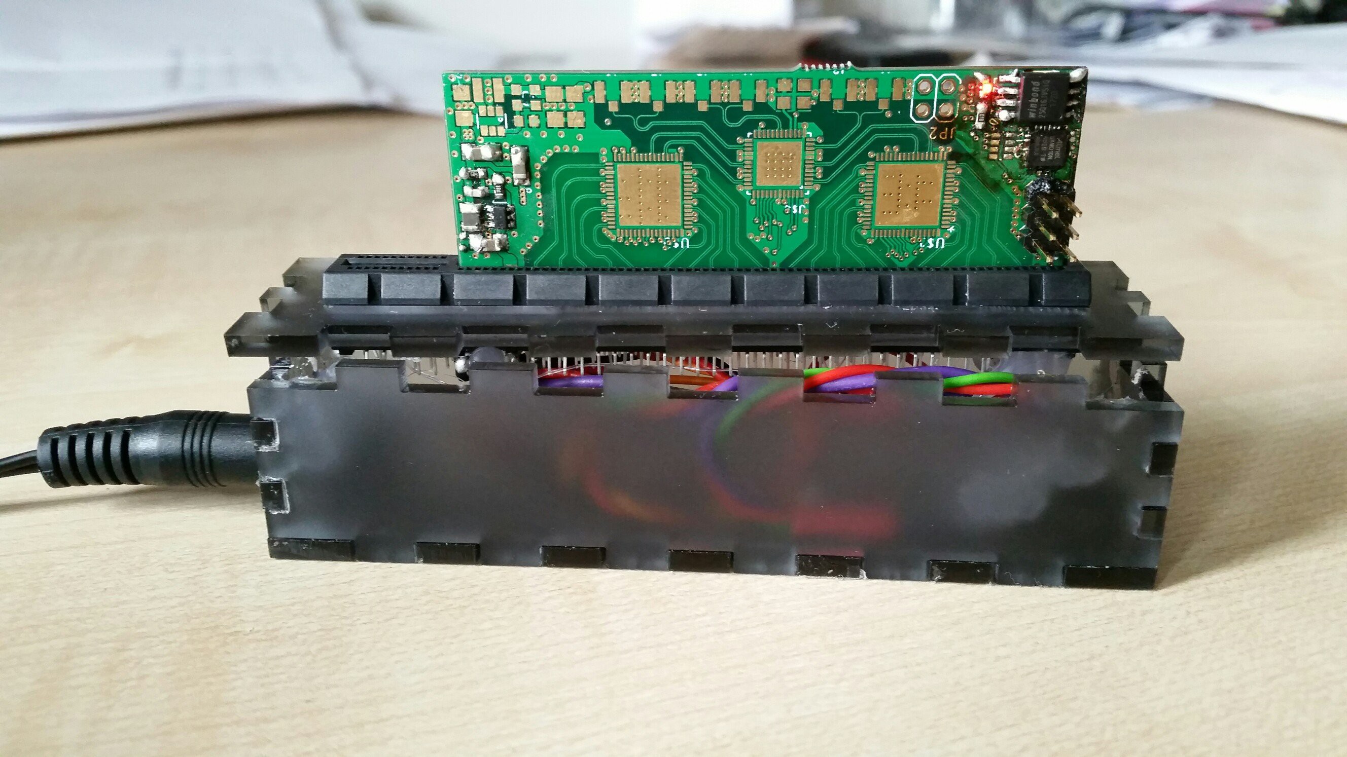
Currently, I am waiting for the stencils and the solder paste. I made an adapter to connect the power supply and the programming UART to the boards. I allready broke the pins of one PCI-e connector, turns out they are quite fragile. Therefore, I decided to also make a small laser cut enclosure to add some rigidity.
To test the basic operation I clumsily soldered on the SAMD10D13, a flash, and the 3.3V power supply. I was able to flash a small "hello world"... and it blinks :-)
Looking forward to get the FPGA board working!
Discussions
Become a Hackaday.io Member
Create an account to leave a comment. Already have an account? Log In.