Close
0%
0%

E-ink Adapter

A small Compact E-ink / E-Paper Adapter for use with a Variety of Waveshare Modules

Public Chat
Similar projects worth following

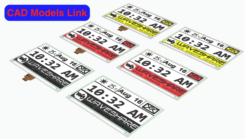
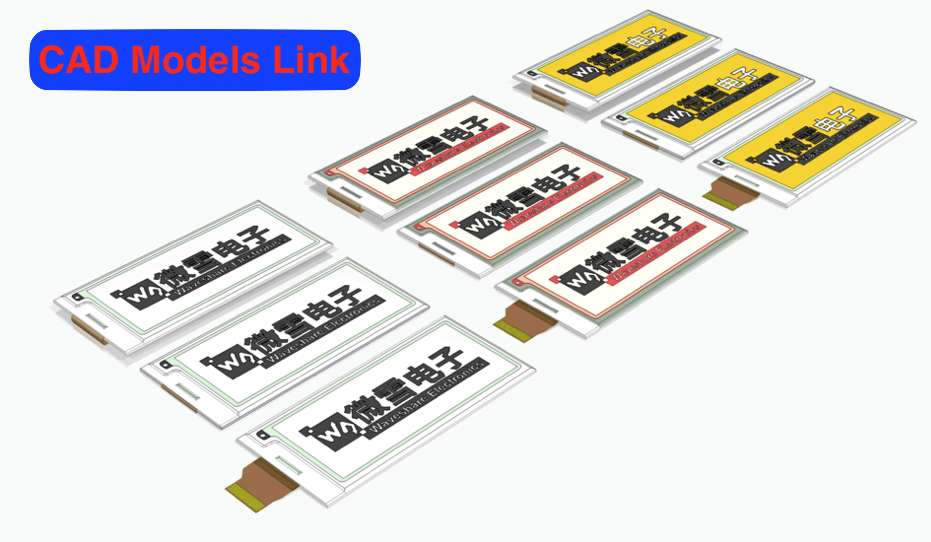
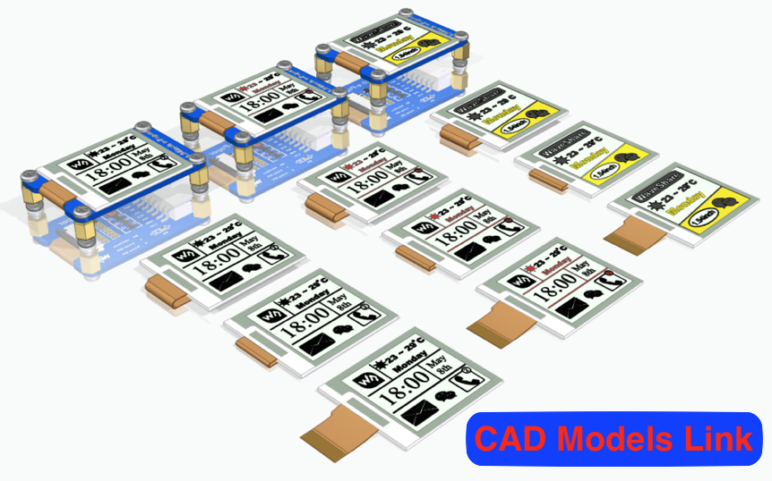
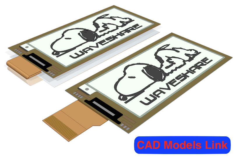
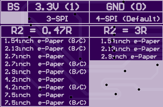
This Adapter Works with 3.3V - 5V Logic and Power with most of the Waveshare e-ink Displays.  The Resistor and Jumper Configuration for all these modules can be found printed on the back of the board.
E-Paper-Rev1.zip

Oshpark Design Files

Zip Archive - 24.22 kB - 04/05/2019 at 01:45

Download

E-Paper-Rev1 - Schematic.pdf

Adobe Portable Document Format - 290.83 kB - 04/05/2019 at 01:29

Preview

E-Paper-Rev1 - PCB Traces.pdf

Adobe Portable Document Format - 264.38 kB - 04/05/2019 at 01:29

Preview

  • 1 × 3R(2 Color) or 0.47R (3 Color) 0805 Resistor
  • 5 × 100nF (0805) Capacitor
  • 1 × 68uH (CD43) Inductor
  • 1 × Header (1x8) 0.1" Electronic Components / Misc. Electronic Components
  • 1 × Jumper (0805) 0ohm

View all 14 components

View all 3 project logs

  • 1
    Logic Level

    The TXS0108EPWR Provides Logic Level Conversion.  If Microcontroller is already 3.3V you can remove the TXS0108 and short the PCB Connectors As Shown.

  • 2
    Code

    Code For each Display can be Found on the Waveshare Wiki

    https://www.waveshare.com/wiki/1.54inch_e-Paper_Module

View all instructions

Enjoy this project?

Share

Discussions

Simon White wrote 07/29/2021 at 11:58 point

Hello John,

I’m so pleased to have found this project, having struggled to eliminate the current draw of Waveshare’s “e-paper Driver HAT” for a battery-powered project of mine.  Waveshare eventually confessed that their HAT continues to draw current even when the both the micro controller and the e-ink display are put to sleep.  Not much good for a long duration battery project.

Anyway, your schematic has helped me to unravel the problem far more easily, and I have now made a version of my own - eliminating all the voltage regulator circuitry as my project is running on a stabilised 3V3.

With only the elements essential to the e-ink display, the board is just 21 x 25mm.  It should suit any barebones ESP8266 or 3V3 Arduino project.

Thank you for your efforts, I’ll post any results or further thoughts here.

  Are you sure? yes | no

bik1rdr wrote 11/18/2020 at 22:08 point

Hi,

How did you decide to use 0805 for the capacitors and CD43 for the inductor?

  Are you sure? yes | no

scottalmond wrote 02/16/2020 at 01:41 point

I'm grateful you have read through WavShare's documentation to decipher their schematic and posted your findings here.  They did publish a new rev in January and they now list C3 (between the diodes) as 4.7uF (IS 4.7 uF, WAS "104"), whereas you appear to be using 100 nF.  Do you have any thoughts on this?

https://www.waveshare.com/w/upload/5/5b/1.54inch_e-Paper_Schematic.pdf

  Are you sure? yes | no

John Loeffler wrote 02/17/2020 at 15:30 point

It may be an error but here is waveshares older schematic (2018)

https://www.waveshare.com/w/upload/archive/5/5b/20200103064017%211.54inch_e-Paper_Schematic.pdf

I have tested it and the 100nF is what I have installed and it works.

 I haven't tested it with larger displays yet.

  Are you sure? yes | no

Similar Projects

Does this project spark your interest?

Become a member to follow this project and never miss any updates