Scott Clandinin
-
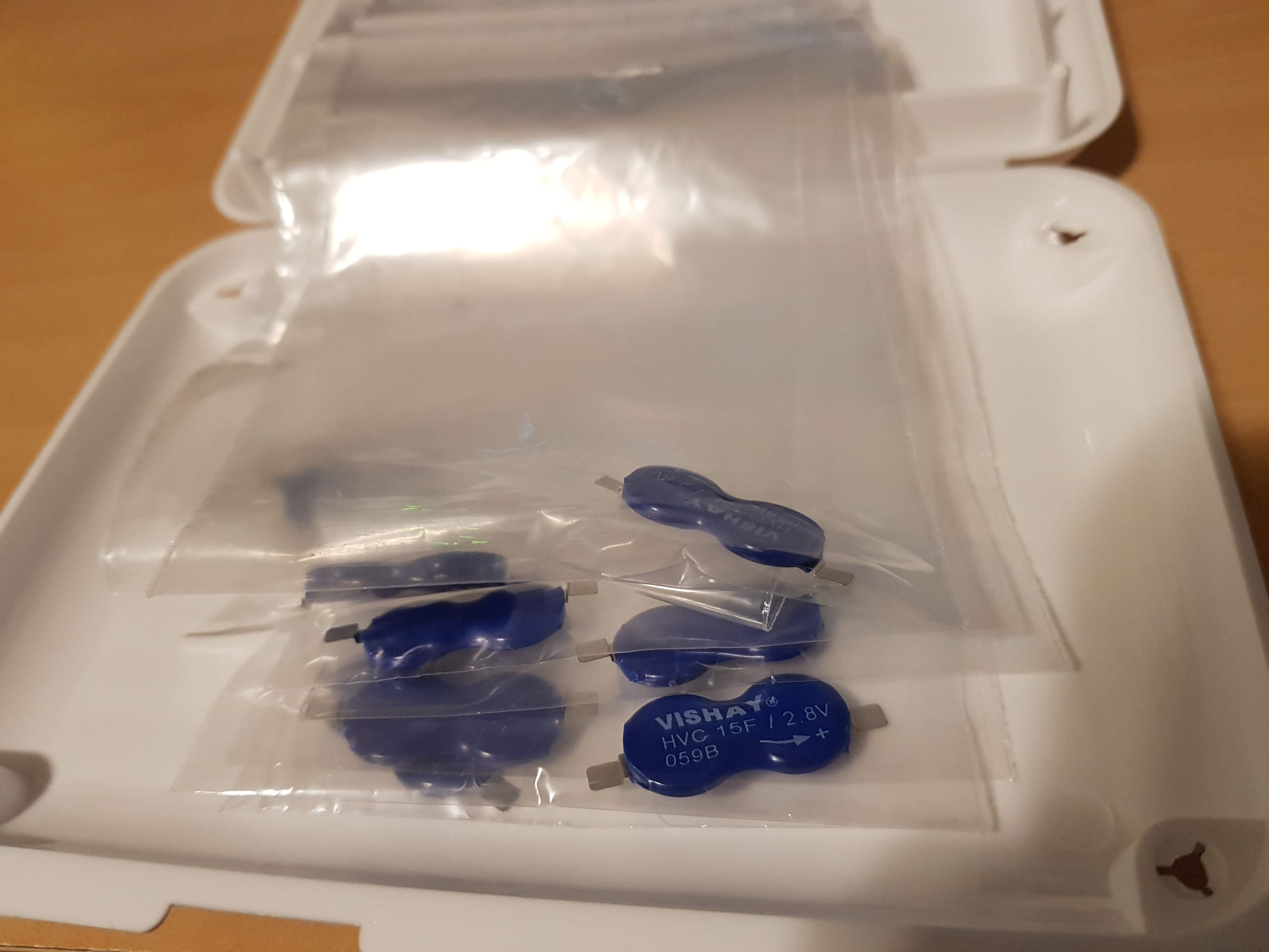
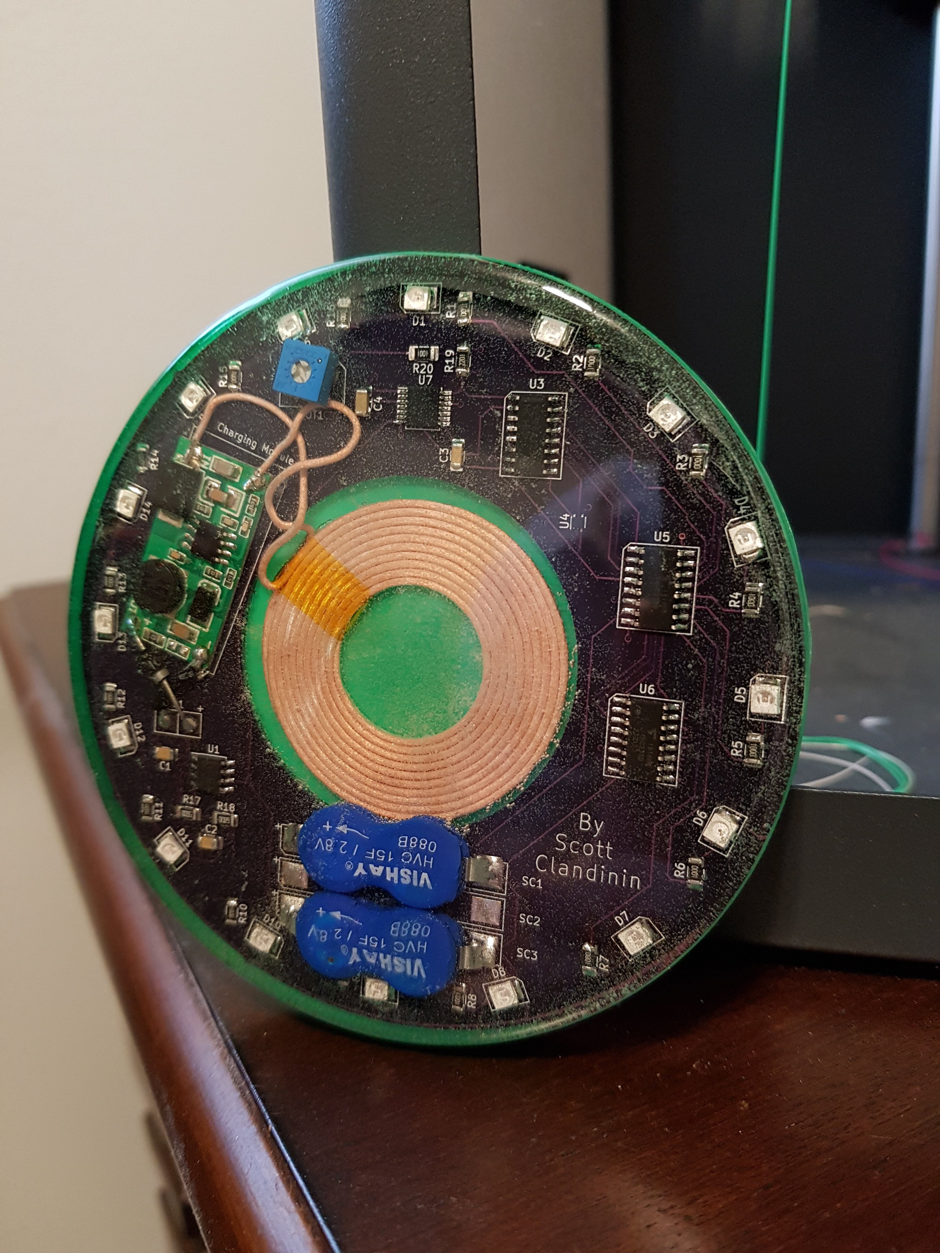
Vishay Supercapacitors
08/20/2019 at 06:00 • 0 commentsThe folks at Vishay were nice enough to notice my project and send me some samples of the same capacitor type I've been using for energy storage. This was quite fortunate as Digikey out of stock with a fairly long lead time. This will help me to be able to work on future iterations of the project, so big thanks to Walter @ Vishay.
![]()
I was also linked to some documentation on the capacitors regarding efficient charging to maximize the lifespan and capacity of the caps.
http://www.vishay.com/docs/28427/pmansolcvpulcharhybcaps.pdf
I haven't incorporated any of these best practices into the current project, but I will be looking into this on future revisions.
-
REV0 Video
08/18/2019 at 00:48 • 0 comments -
Production Costs
08/11/2019 at 05:50 • 0 commentsOptimizing parts, vendors, and process when planning to scale for production is no easy task. This years Hackaday prize is a good exercise for me as I've never looked at any project as a potential commercial project, only as a prototype as a hobbyist.
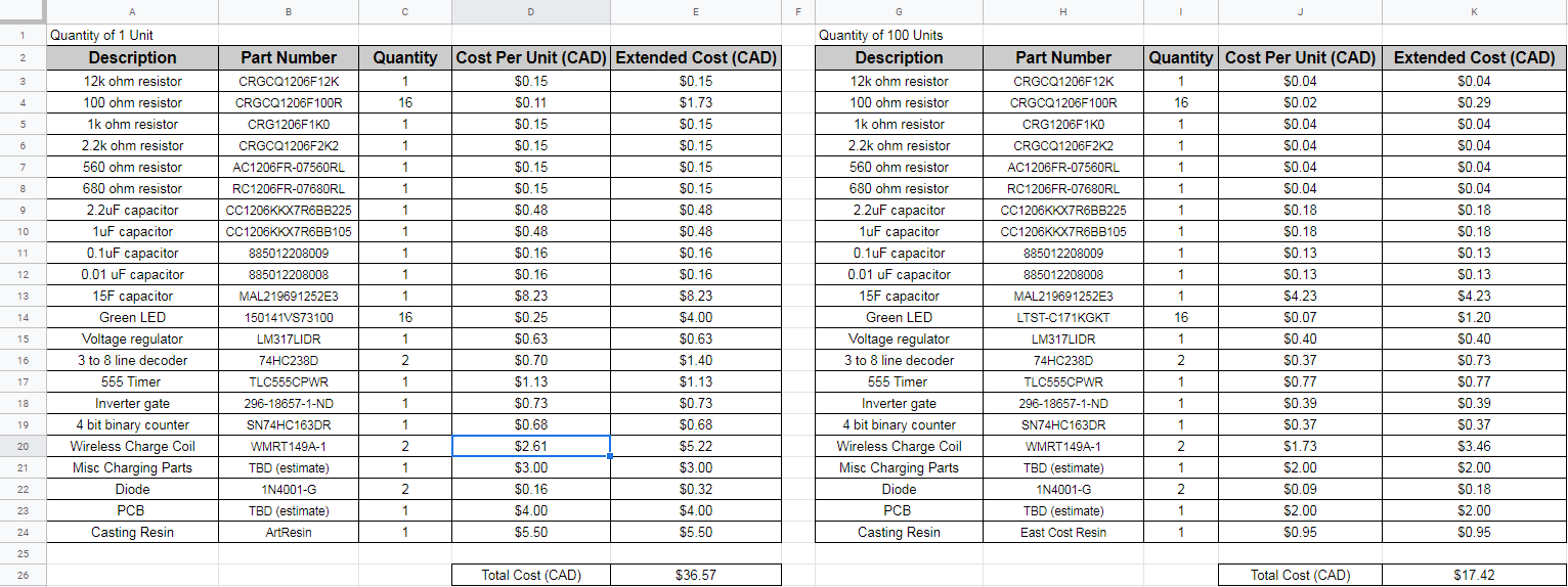
I've come up with some numbers to get an idea of my cost per unit when I would be ordering parts for 100 units. This certainly won't be a final BOM, and some estimations are made, but will give me some kind of idea what the material costs would be.
![]()
If I were to order parts to make another unit I would be spending around $35-$40 CAD. If I were to order parts for 100 units I would be spending around $15-$20 CAD per coaster. The most expensive parts are the supercap and the wireless charging coils and circuitry, making up nearly half of the total cost. Much more research would need to be done into these parts in order to find the best prices.
If I were to make a second prototype the same as the first, there would be about 2 hours of labour involved. This includes hand soldering SMD components, starting 3D prints, pouring resin and clearing bubbles (and light monitoring), and assembling charging base.
Significant time would be saved by:
-using a reflow oven rather than hand soldering all SMD devices (or even using a 3rd party PCB service to solder most of the components during manufacturing).
-relying less on 3D printed parts, and more towards professionally moulded enclosures.
-doing the processes with several units at once rather than doing one to completion.
If brought this to market, a sticker price for this product could possibly be somewhere between $30-$40 CAD with the numbers I have currently.
-
Other LED Coasters on the Market
08/10/2019 at 07:58 • 0 commentsBelow are a few examples of LED coasters that are commercially available. In addition to these, there are a handful that can be found on
FlashyBlinkyLights Infinity LED Coaster
https://www.flashingblinkylights.com/infinity-tunnel-led-coaster-sku-no-11051.html
Cost for one: $5.30 CAD (price breaks available on higher qty)
Device uses two CR2032 batteries (included). Price is good, but the major cost over a long period of time would be the batteries themselves unless those too are bought in bulk. It isn't described how long this can go until battery replacement is required, but likely multiple times a week. Coaster height not advertised.
FlashyBlinkyLights Pressure Activated LED Coaster
Cost for one: $5.30 CAD (price breaks available on higher qty)
This is a pressure activated LED coaster. Device uses two CR2032 batteries (included). Price is good, but the major cost over a long period of time would be the batteries themselves unless those too are bought in bulk. It isn't described how long this can go until battery replacement is required, but likely multiple times a week if used regularly. Coaster height not advertised.
Glow Products LED Coaster
https://glowproducts.com/ca/multibigbasecoaster?___store=ca&__from_store=ca
Cost for one: $2.90 CAD (minimum qty of 6 required)
Another pressure activated LED coaster. Device uses 3 AAA batteries (not included). 24hr of continual use between battery changes. There would be a large cost in batteries for regular use. 20mm coaster height.
Brag Gear Retro Lights LED Coaster
https://braggear.com/products/retro-lights-led-coaster
Cost for one: $19.99 CAD (price breaks available on higher qty).
Device uses two CR2032 batteries (included). Battery life likely below 24hr. 4mm coaster height.
Conclusions:
Most LED coasters out there are quite cheap when you don't consider battery purchases. Regular commercial use of these coasters would add up in price and environmental impact with regular replacement of multiple batteries per coasters.
A smaller number of coasters out there have direct DC power connections or include a USB port for charging a rechargeable battery.
From my search, there does not appear to be any LED coasters out there (commercially available at least) that are either wirelessly charged, or uses capacitors for energy storage rather than traditional batteries. The following benefits of my design may be enough to justify a higher price point:
- Easy wireless charging.
- No continual battery purchases. Smaller environmental impact as there will be no batteries or battery packaging that will end up in a landfill.
- Hardier design than competitors (fully sealed and protected from moisture).
- Aesthetic design displaying circuitry.
I will be reworking my BOM pricing based on buying parts in bulk, and some redesigning to be able to use less supercaps. The the project log will go over the cost to manufacture and a possible sell price to compare to existing coasters.
-
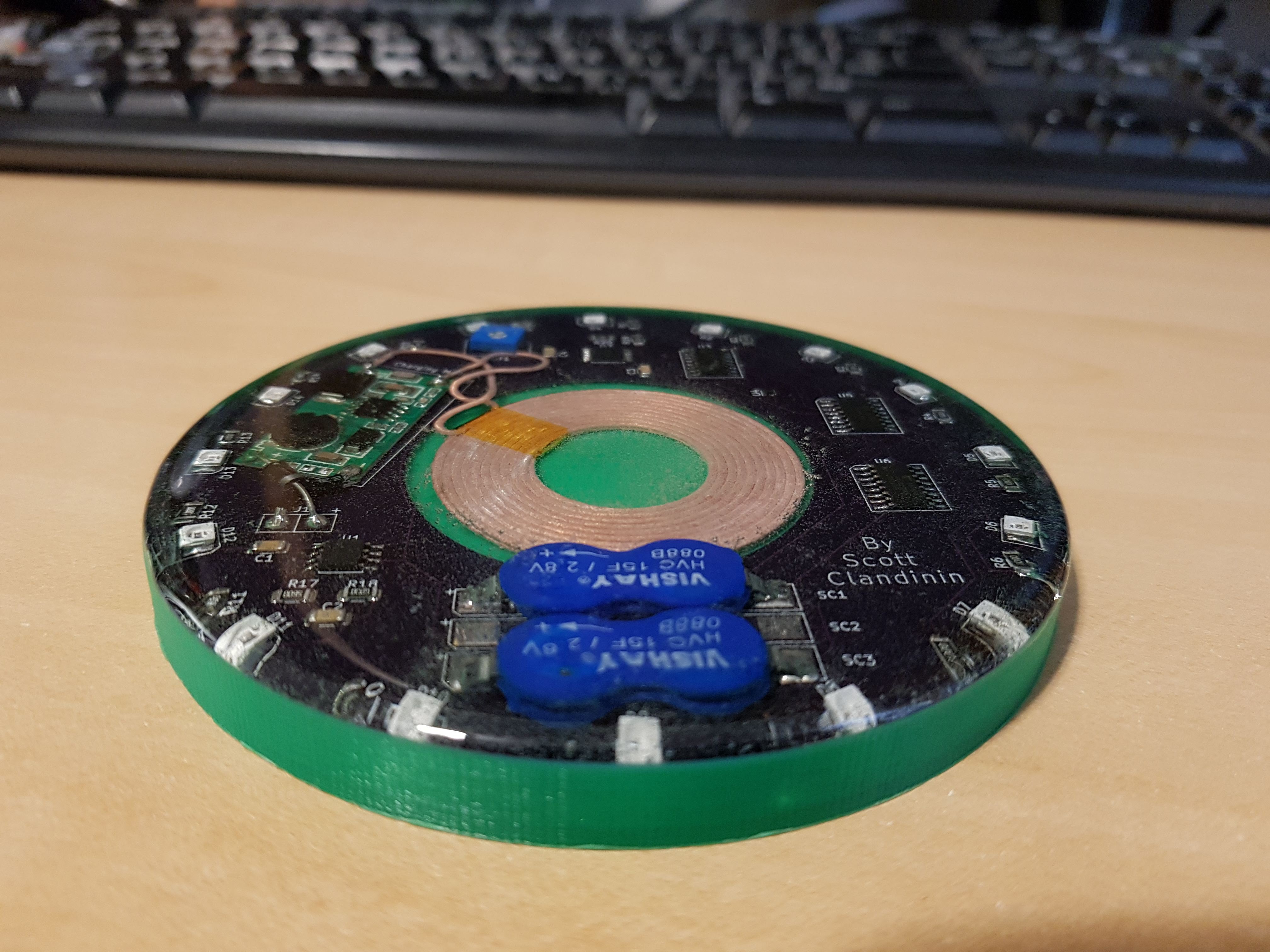
Slimming the Coaster
08/09/2019 at 23:24 • 0 commentsThe next stage of the design will also be focusing on making a thinner coaster.
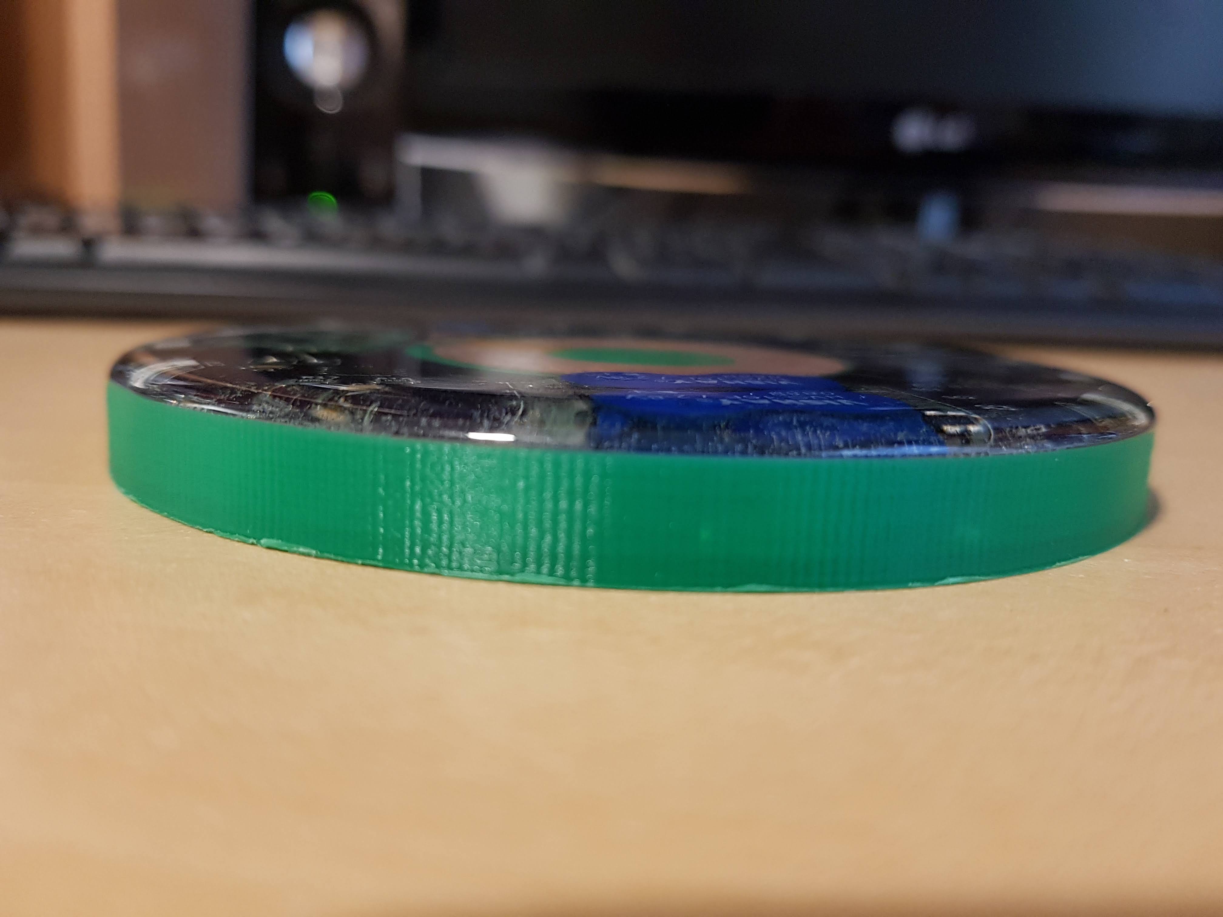
The coaster is about 11mm high. About 8.5mm of this is the 3D printed base, with about 1.5mm rising above the base for the curved finish of the resin.
![]()
With some rearranging and recessing, I can bring this total height down.
![]()
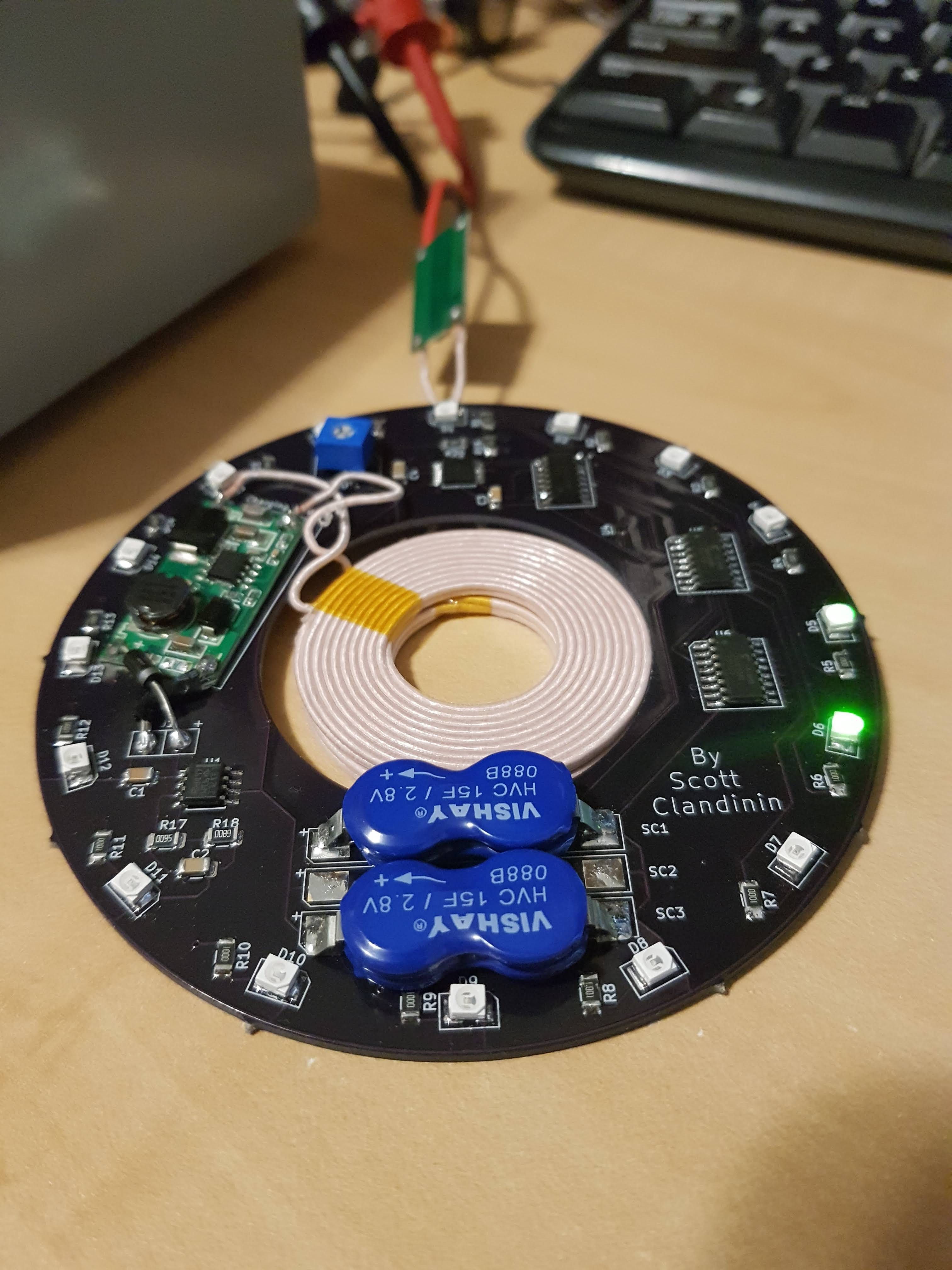
1. The potentiometer in the top left will be replace by a SMD resistor. I only included a pot in so I could test at different clock speeds.
2. The coil receiver circuit board can be removed and the components can be designed into my circuit board. The leads from the coil will be shortened to keep them low to the board.
3. Similar to the cut-out for the coil in the middle, I can leave a space for the supercaps to be recessed in as to not add height.
With this arrangement, the highest component would either be the LEDs (2.1mm) or the inductor (TBD). I'll be safe and assume the highest component will be 2.5mm from the board. The calculation for a rough total height would be:
3D printed base + PCB thickness + highest component + resin overhang
0.7mm + 1.6mm + 2.5mm + 1.5mm = 6.3mm
With these design changes I would able to decrease the height by 4-5mm.
Besides the better aesthetic of a slimmer coaster, it would also use a bit less casting resin and 3D printed material. The 3D printed material cost is mostly negligible but a decrease in print time would decrease the overall bulk manufacturing time if I were ever to try to scale up production.
-
Drawing Less Power
08/08/2019 at 06:28 • 0 commentsThe first prototype is complete. With the next revision I will aim to minimize the current draw to extend the time. If this were to become economically feasible, I will need to use less super caps, possibly down all the way to just one 15F.
Run Time Extending Changes:
-rather than have my output of the regulator at 2.75V I can increase that to 2.8V (voltage rating of supercaps).
-adding a diode between the output of the regulator and the caps will ensure that no current flows back through the regulator circuit when the supply is removed. The resistor divider network in the regulator would draw a little over 2mA passively. With a diode in place there is no way for the caps to back-feed into the resistors.
-using a lower power timer/osciallator. My 555 timer has a listed current draw of 250uA, while there are some available I've seen that are listed as low as 50uA.
-use LEDs with a lower current draw and 1.8V forward voltage.
A Hackaday user also recommended a buck/boost converter to use to bump the voltage back up once it falls below a usable value. This is something I will look into as well.
-
First Video Demonstration
08/06/2019 at 03:57 • 0 comments -
Turning it into a coaster
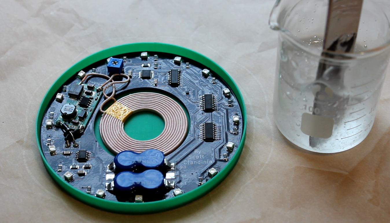
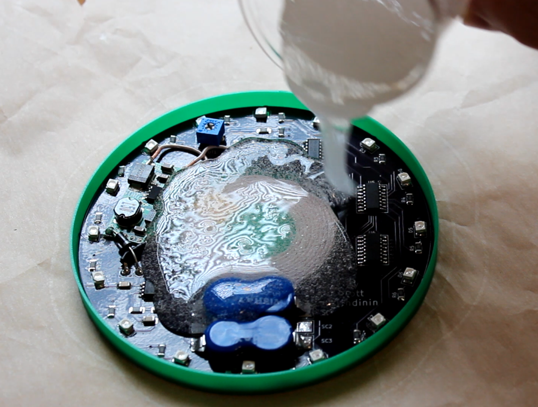
08/02/2019 at 02:43 • 1 commentThe board was complete and working, the next step was to actually turn it into a coaster. Rather than use a piece of glass or acrylic, I wanted to pour in a clear resin to give it a smooth and seamless finish.
I used art casting resin for this. The way this resin is used is by mixing a resin in with a hardener and pouring in. It was a self-leveling fluid, so all I needed to worry about was putting it on a level surface.![]()
![]()
![]()
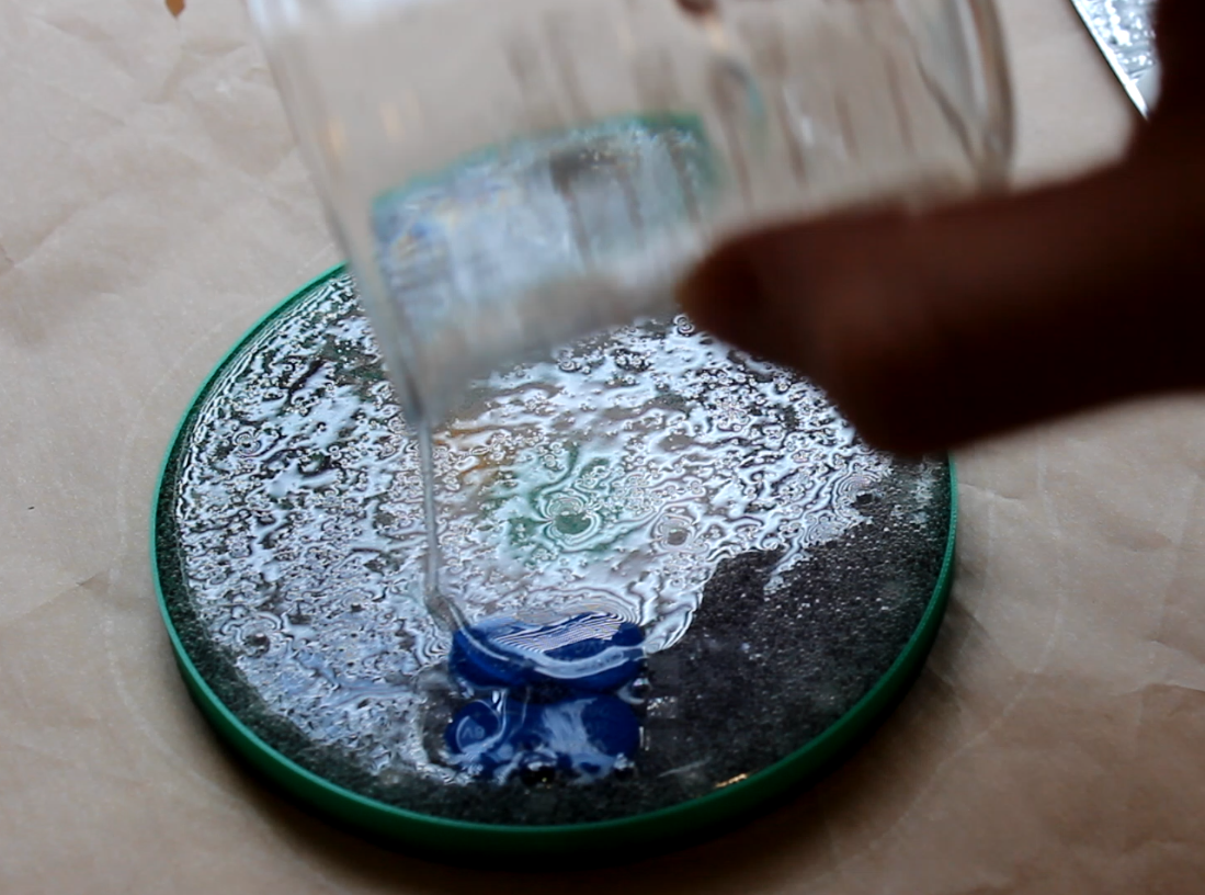
In order to have a clear finish, a lighter or torch must be used on the surface of the resin to bring the air bubbles to the top. A small torch would have done the best job, but I used a lighter as I had it on hand. Care needed to be taken with how long I applied heat to the resin solution, as too much heat could cause damage to the electronics (the insulation on one of the caps was slightly melted). It's key to stay on top of bubbles, as new bubbles will arise even up to 30-40 minutes after the pour.
I would have had a clearer finish with a torch, but the result was decent, albeit a bit cloudy. An error I made was not applying the lighter heat until several minutes after the pour. I waited longer than I should have for it to self-level and clear some bubbles on it's own. After pouring there is only a fairly small window of time before the solution begins to harden.
![]()
![]()
![]()
The imperfections are noticeable up close, but from a distance the coaster still looks great. I will took what I learned from this first pour into making the second coaster more clear.
-
Coaster Enclosure and Charging Base
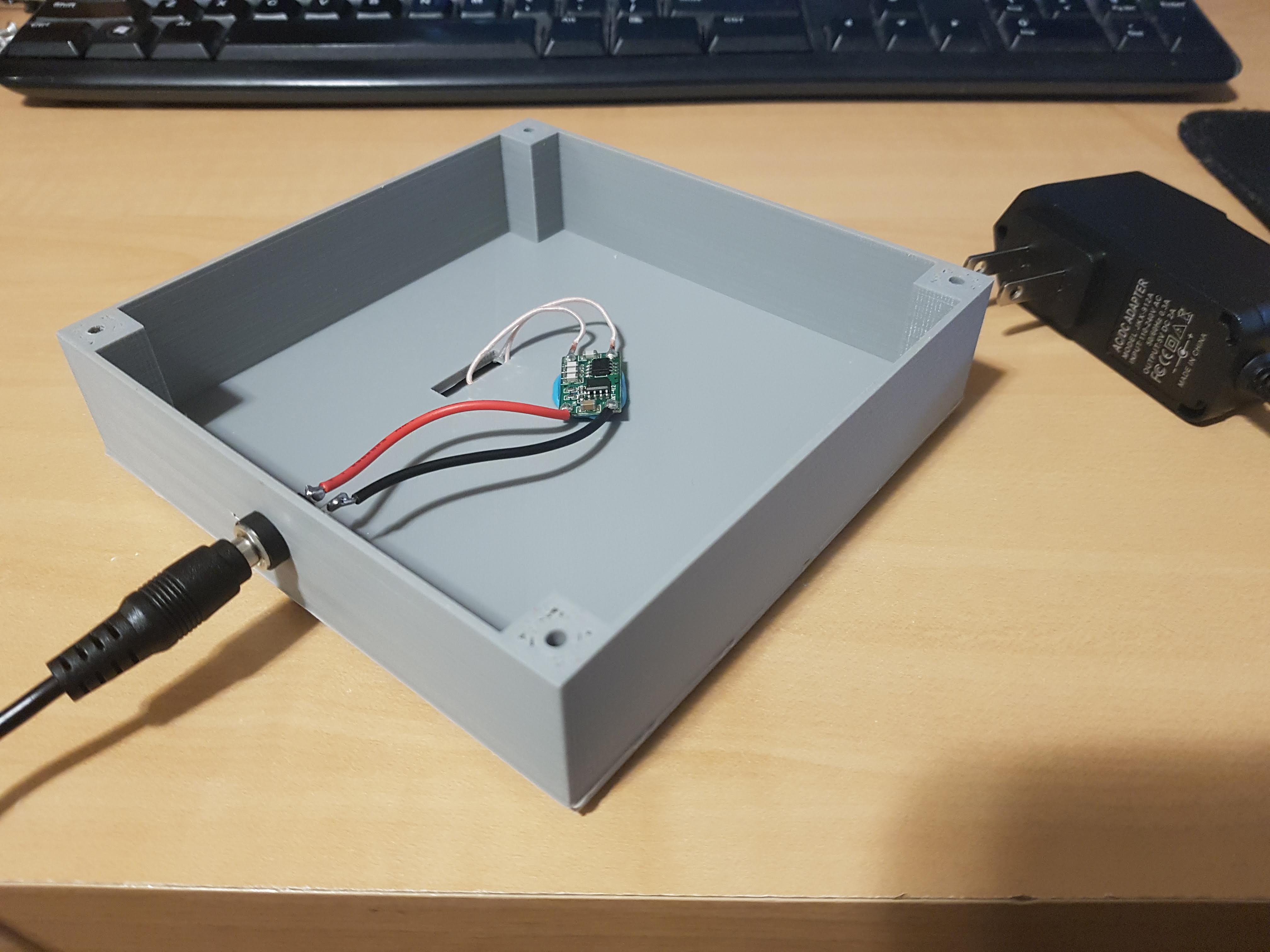
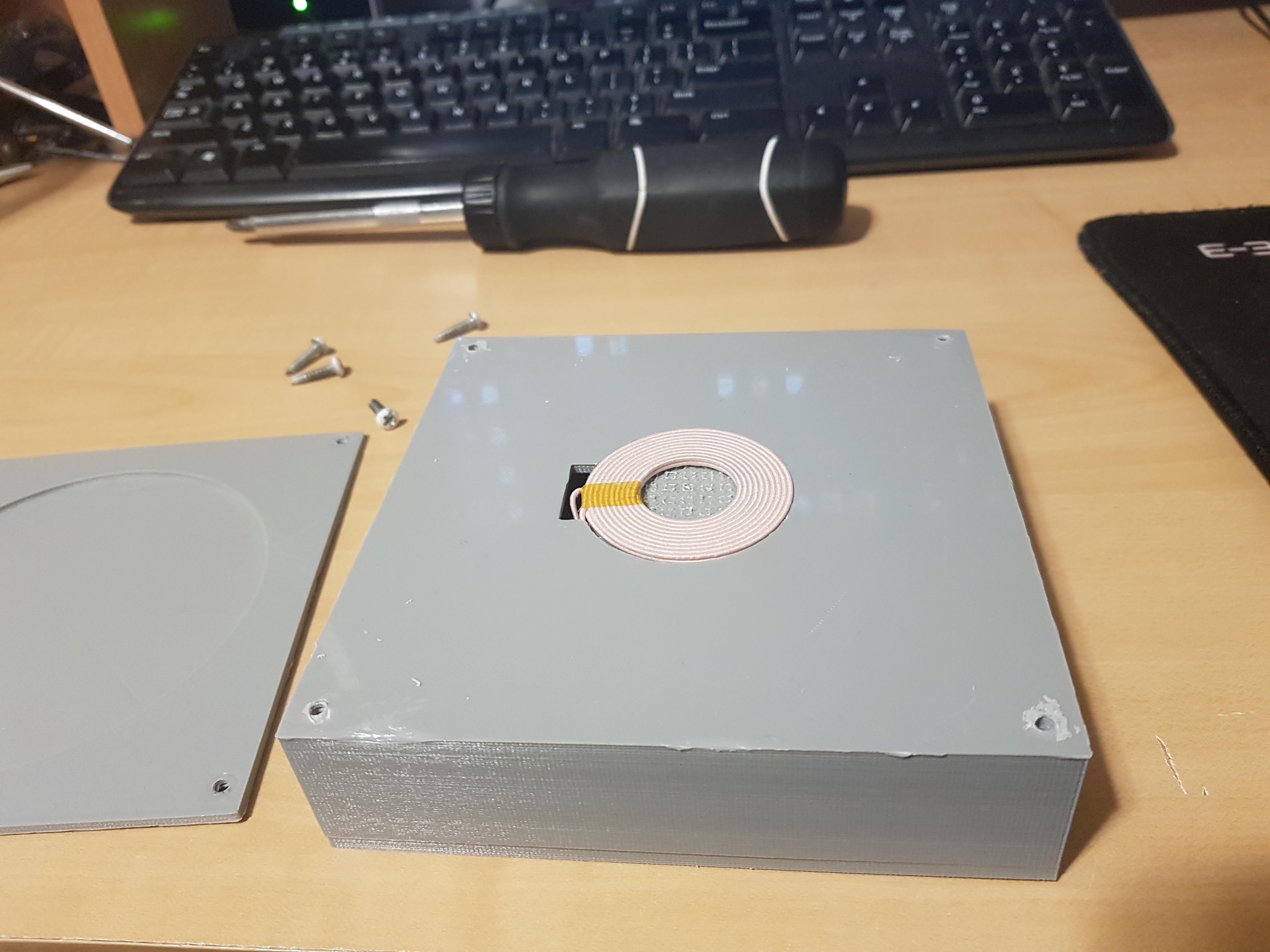
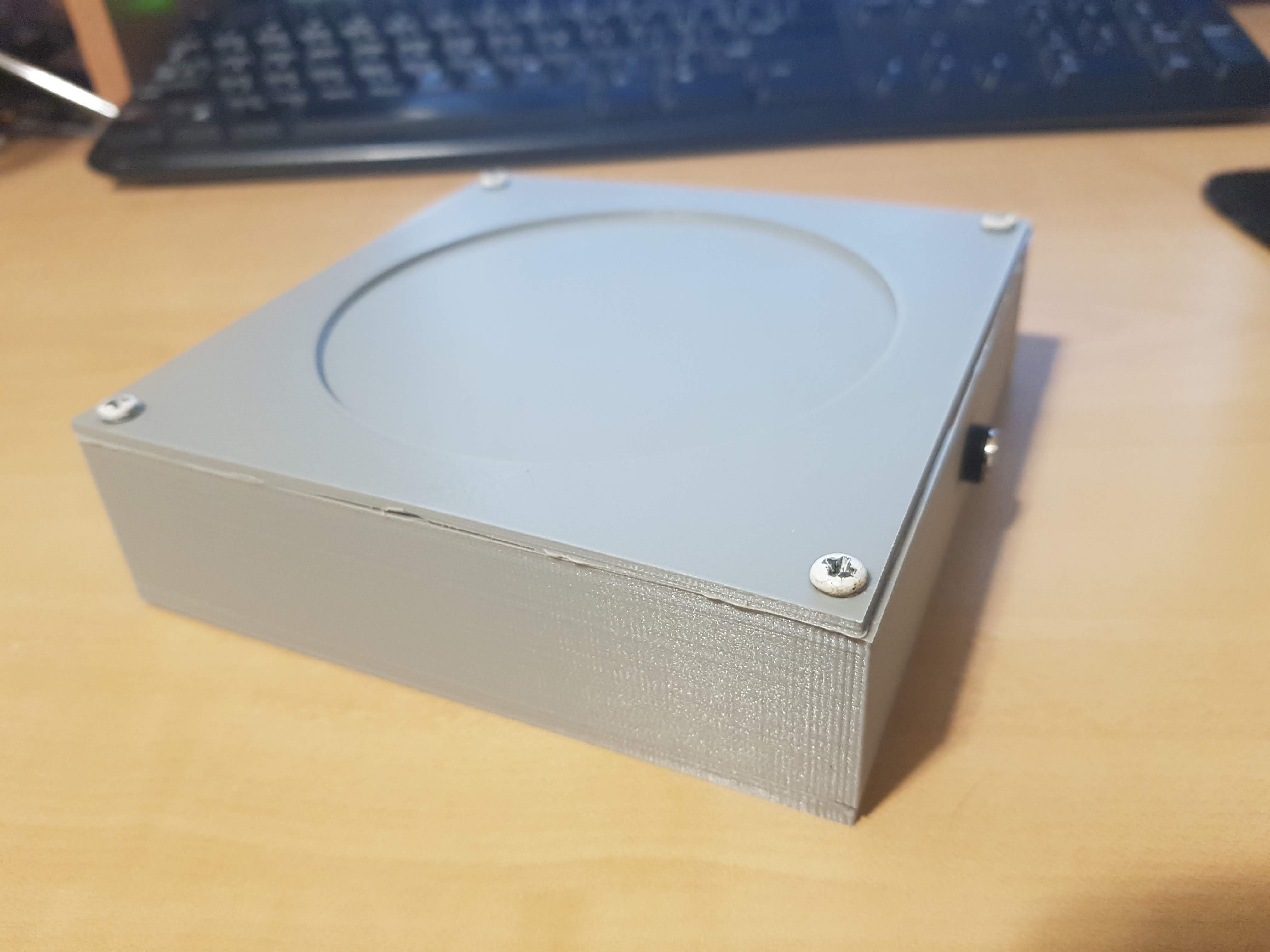
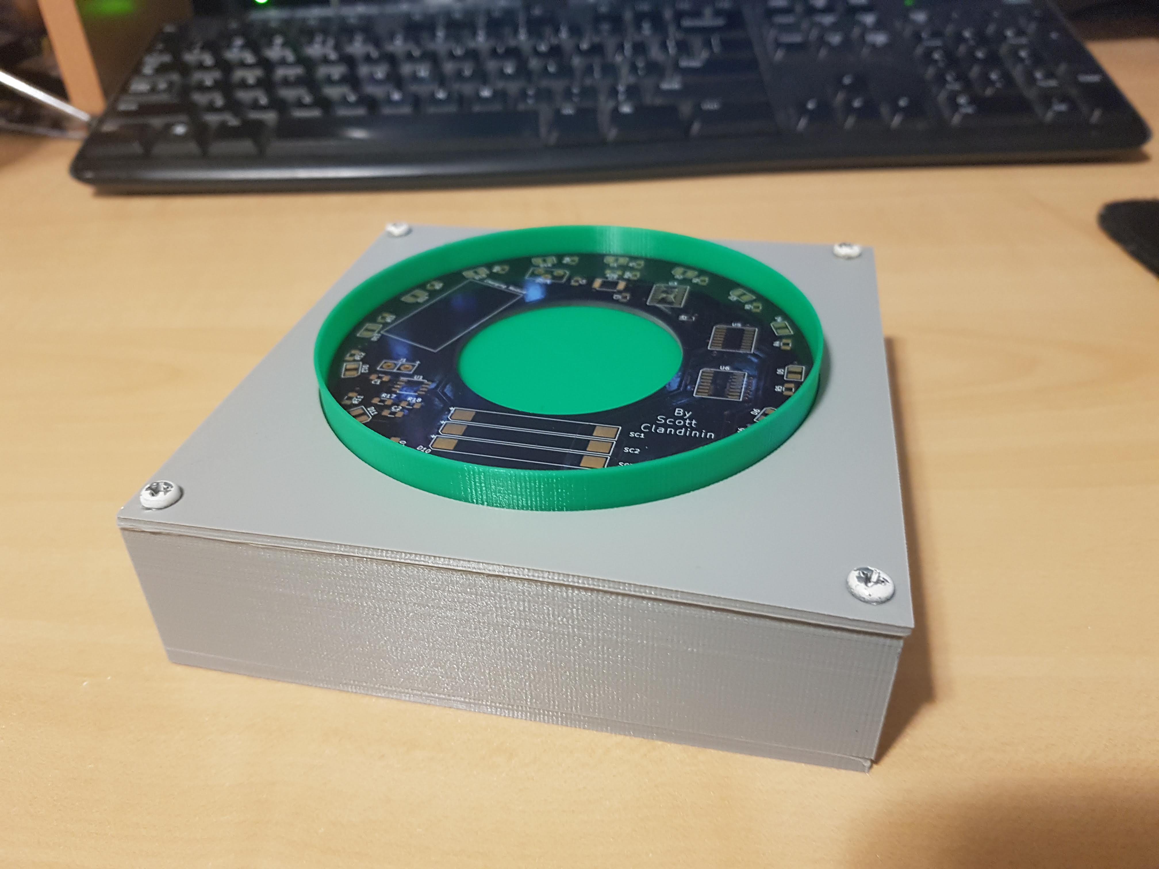
08/01/2019 at 04:38 • 0 comments![]() From left to right: Coaster body, charging base top, charging base body, charging base bottom.
From left to right: Coaster body, charging base top, charging base body, charging base bottom.![]()
![]()
![]()
![]()
In future versions the charging base will have a more aesthetic design, but this will suffice for now.
-
Capacitor Storage
07/03/2019 at 05:50 • 0 commentsCurrent Draw
With two sets of stacked super caps, the total storage is brought to 60F.
The below is the current draw of each major component. This doesn't encapsulate everything, especially with changing supply voltages, but it is a good show of how the LEDs have the majority of the current draw.
555 Timer: 0.25mA4-bit binary counter: 1uA
4-16 bit decoder: 8uA x 2
Single LED: 27.5mA
I selected the regulator to be 2.75V (just under the 2.8V rating of the caps). Since the forward voltage of the LEDs is 2V, this device has a useful range of only 0.75 volts. Once below 2V, the LEDs will no longer light up and the device will slowly bleed out the remaining energy.
Charging Time and Run Time
Upon powering the device with the charging coil, the caps quickly charge to 90-95% of the max voltage. I originally thought this was "close enough" to being charged. When removing from the supply after less than a minute of charging, the device would run out of power within a very short period of time.
Charging it for longer and monitoring it shows that the voltage quickly ramps up, but flattens out near the peak and takes quite a while to actually reach 2.75V. When giving it a long time to charge completely, the device was able to run for about four hours.
Possible ways to increase run time:
-increase supply voltage (limited by capacitor specs $$$)
-more capacitance ($$$)
-choose LEDs with lower forward voltage
-run LEDs dimmer (larger series resistance)
-find a timer with lower current draw (if available)
LED Coaster - Wireless/Batteryless
A new take on the LED coaster with wireless power charging and supercapacitor energy storage.

 From left to right: Coaster body, charging base top, charging base body, charging base bottom.