AccidentalRebel
-
2019-04-21 to 2019-04-23
04/23/2019 at 00:43 • 0 commentsSince the printer can now print objects properly, the next step is to do advanced calibrations using this guide.
Here's the video of final result after all the calibrations. I never thought I'd reach this level of quality, to be honest.
The print uses 0.2mm layer height resolution and you can still easily make out the layers. The advanced calibrations went through various factors like optimal temperature and speed, extrusion multiplier, retraction distance, and handling overhangs. It's rather extensive and the results are very noticeable as can be seen below:![]()
The above shows the before and after. If you would look closely the resolution of the second one is better as it uses a 0.2mm layer height. It also printed faster too thanks to the increase in speed. The first one took around an hour while the second one took 20 minutes.---------- more ----------Here are all the results of the calibrations:
![]()
One thing that I had to dial down a whole lot after the calibrations was the speed. While my printer can handle speeds up to 40 mm/s, the motors sometimes skips especially if ran for longer periods of time. Plus, higher speeds might also have a negative effect on the health of the motors.
Aside from software calibrations, I also did improvements to the hardware itself. I cleaned the hotend to prevent filament from oozing, I slapped some heatsinks on the motors, loosened the slack on the bowden tube, and improved the setup and orientation of my spool holder. Each may seem trivial but they also contribute a lot to the overall quality.
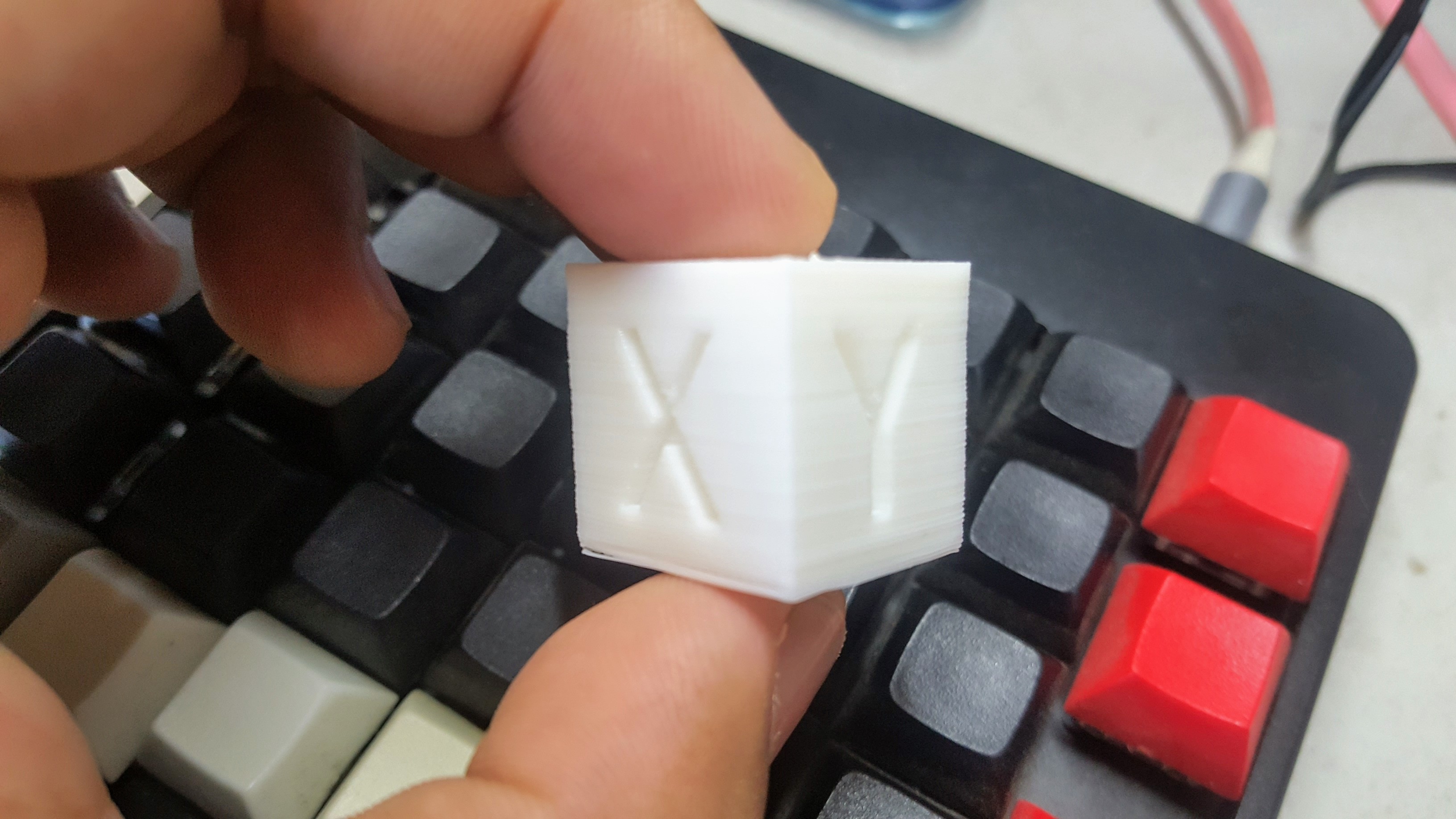
Here's an almost perfect calibration cube thanks to all the optimizations above.
![]()
Up next: Torture tests!
-
2019-04-17 to 2019-04-20
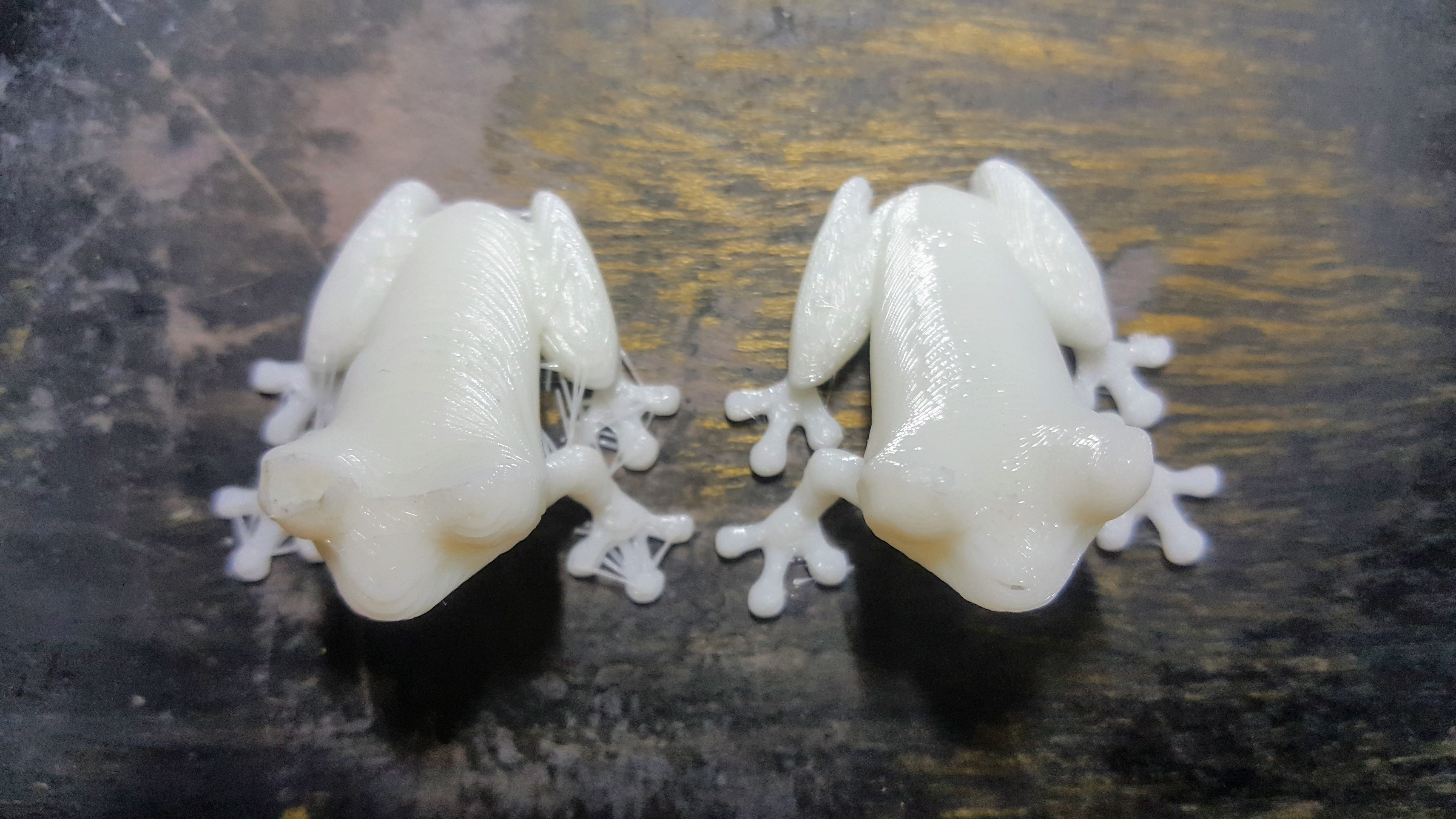
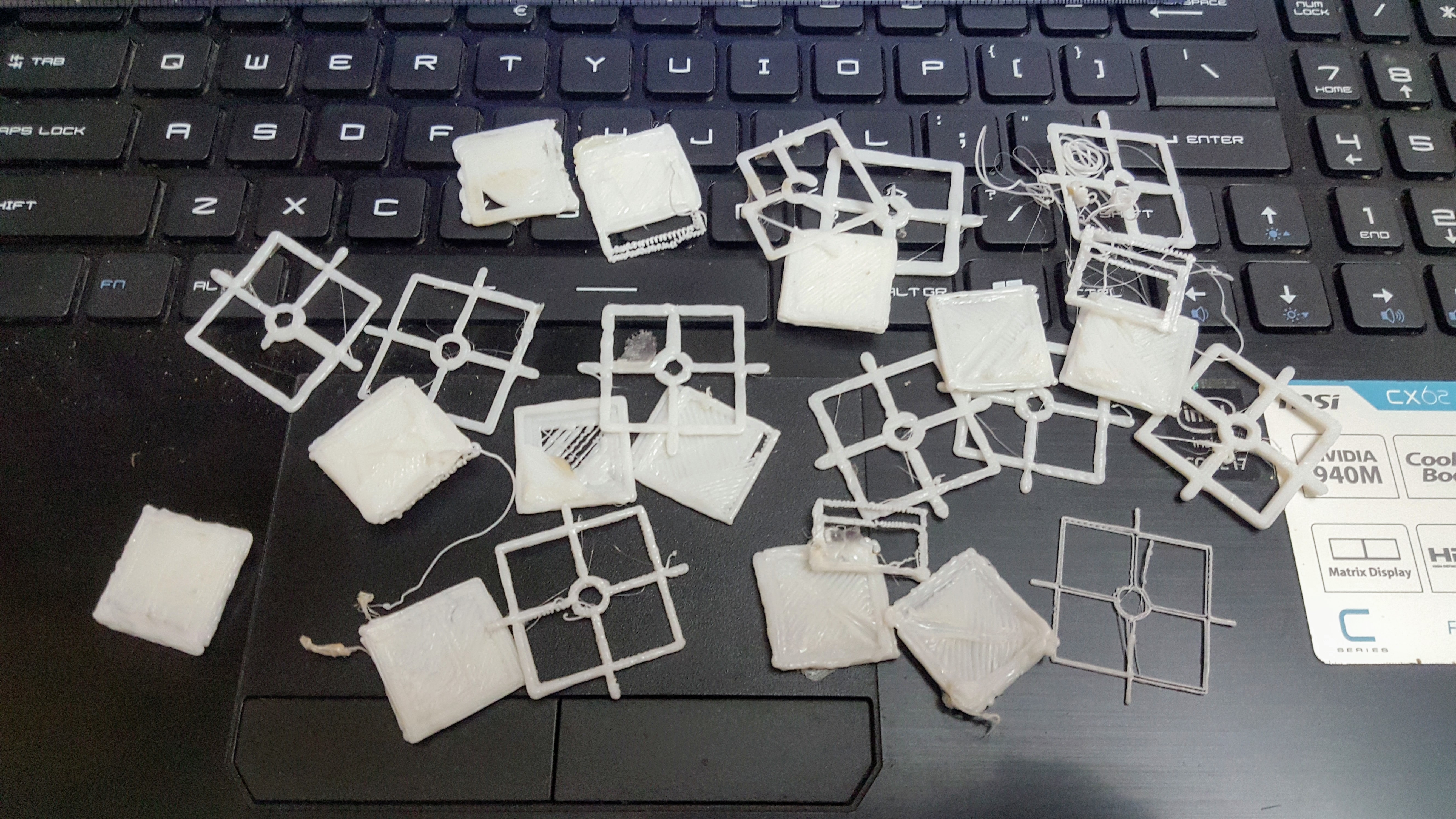
04/20/2019 at 14:20 • 0 commentsBehold, the result of countless hours of calibrations, problem solving, and wasted filaments:
![]()
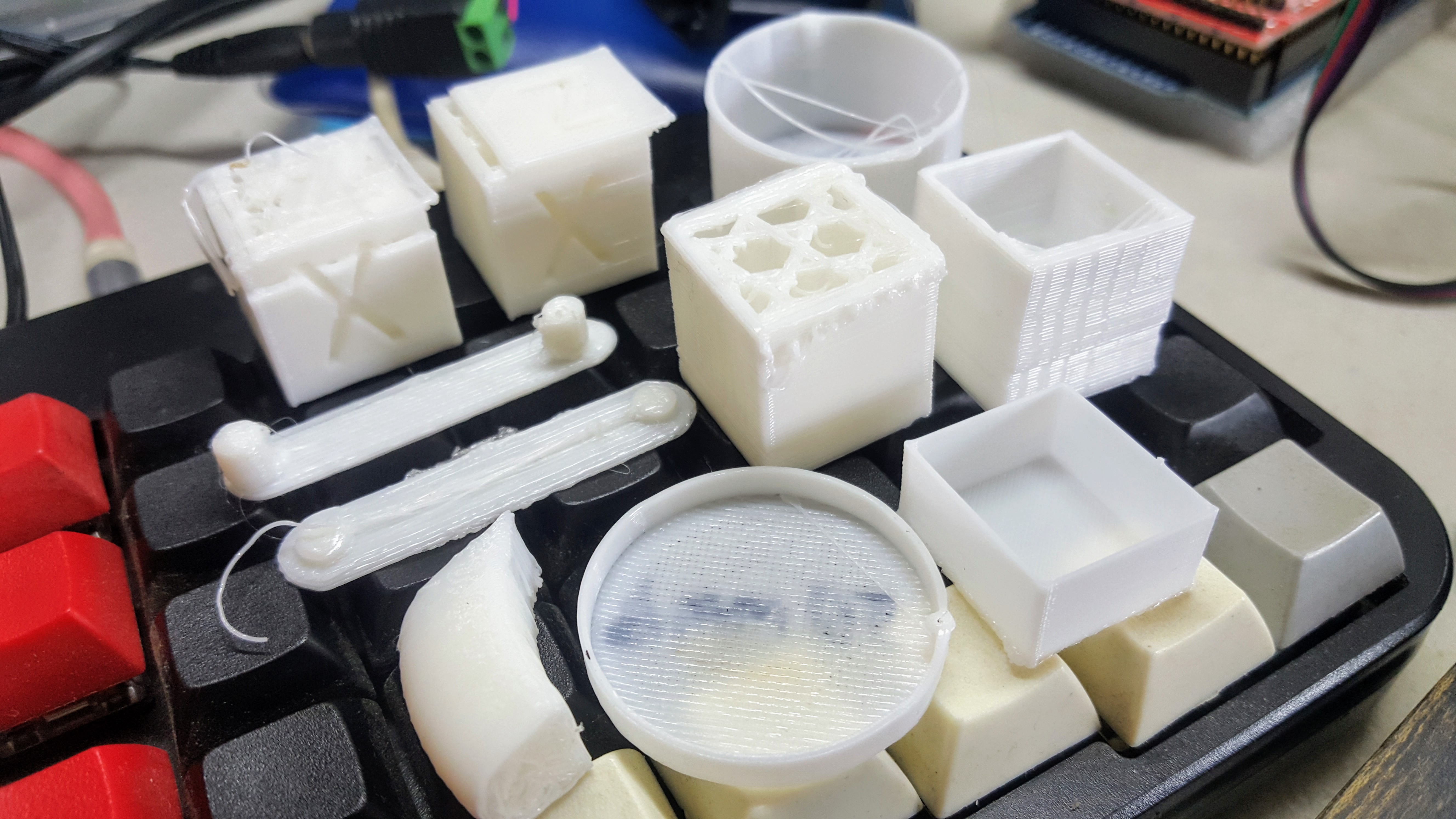
It's not perfect yet. But it's the best out of all the tests I've done so far. Look at all the other failed attempts.
![]()
I knew going in that calibration would be challenging, especially for a home made 3D printer. I had to go through a lot of options both through firmware and slicing program to get to the result above. It's cumbersome but very enlightening to be forced to understand every bit of the machine you are learning.
---------- more ----------![]()
The first lesson that I learned is just how hot the hotend can become. At 200 degrees Celsius it's enough to melt the heatbed and make fingers sore for a few hours. This meant being extra careful around the thing and making sure that it's off when it needs to be off.
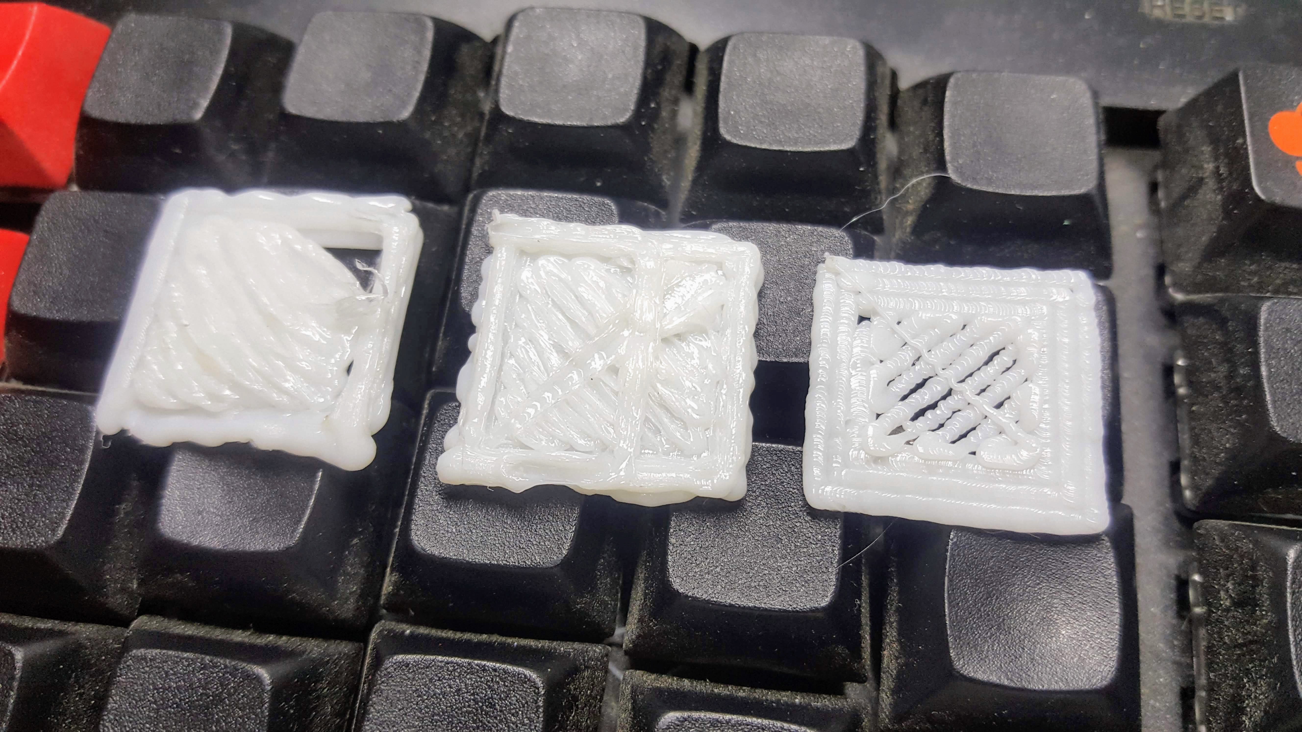
![]()
The picture above shows the first three prints that does not resemble a string of spaghetti. As you can see I've experimented with a lot of settings each giving me wildly different results. This really taught me just how important understanding what each setting does. I had to do research and tried printing it out so I could compare the results.
I also experienced my hotend clogging up. This forced me to open it up and I got real familiar with how it works and how to properly set it up to avoid future clogging. It has not clogged since. Tip: Depending on the quality of your hotend, the filament might not slide inside quite easily if you feed it through. A better approach is to have the filament already inside the tube when assembling the hotend.
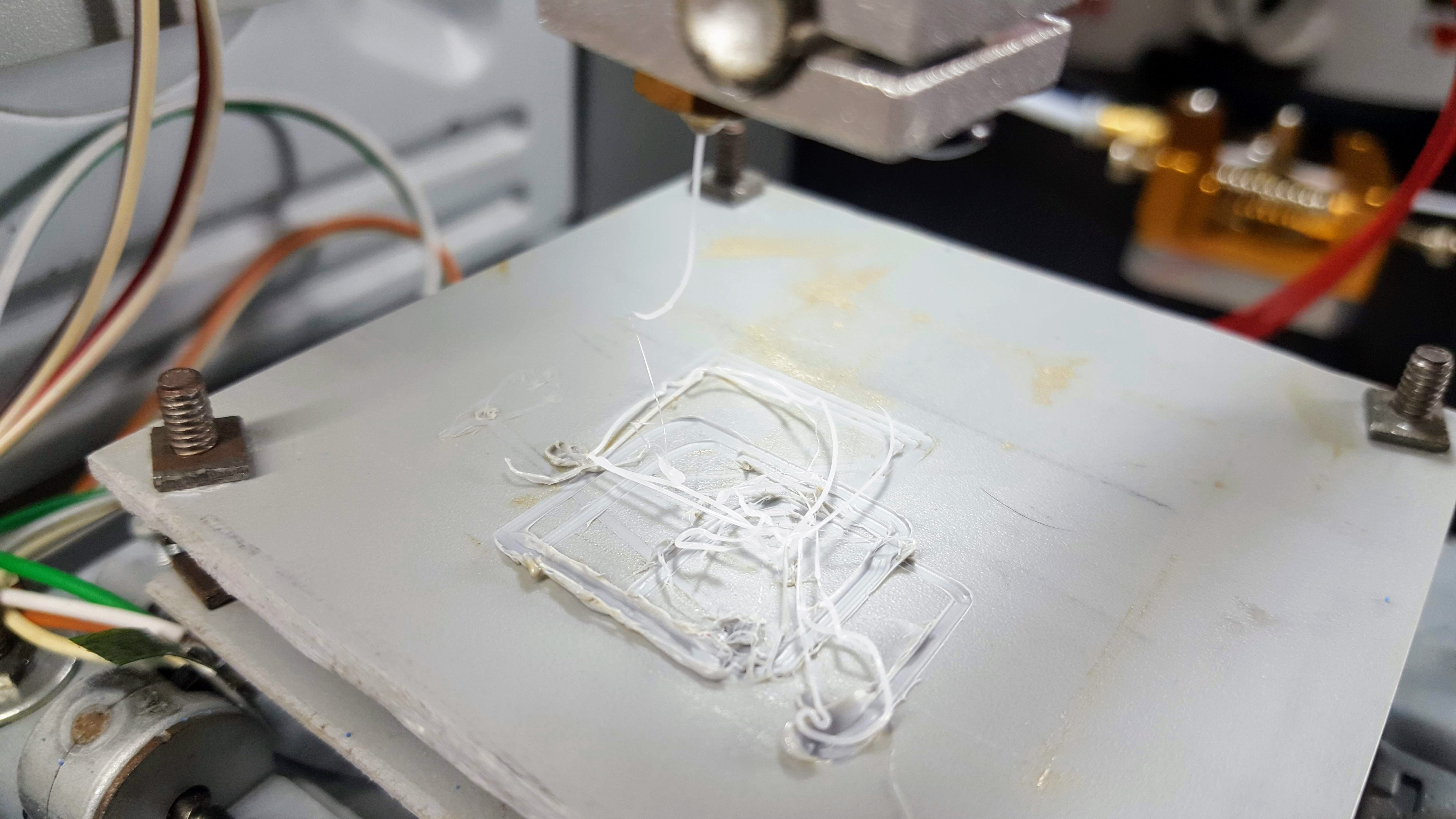
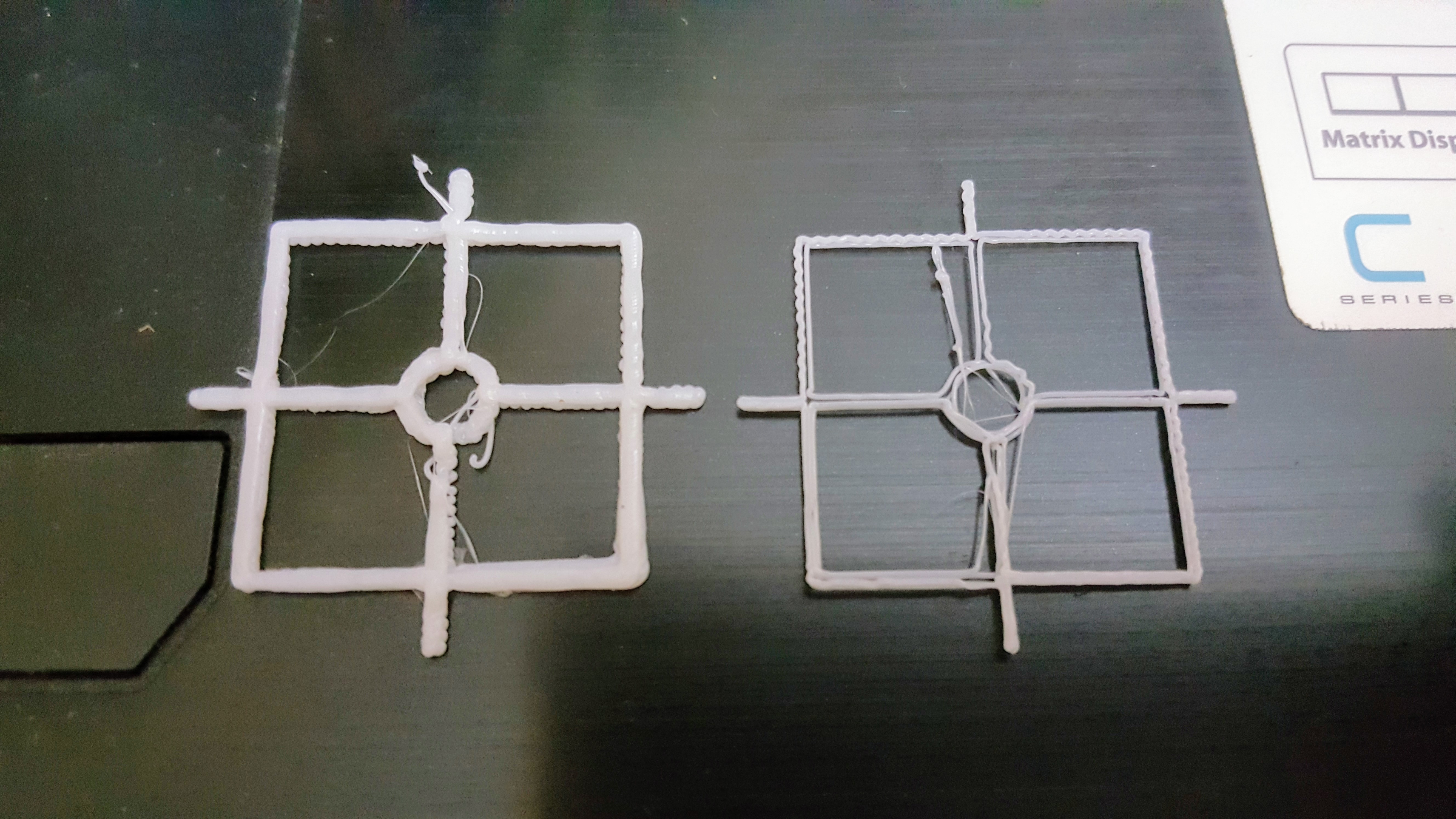
One problem that took a long time for me to figure out was the the infills are getting more filament but only on the second layer onward as shown below. Notice how there's a mound of filament on the top left which the nozzle eventually bumps and ruins the rest of the print.
![]()
This had me testing out various settings like extrusion multipliers, layer combining, layer heights. After many failed tests I learned that I was using the incorrect steps per unit for my extruder making it extrude a lot more than it was supposed to.
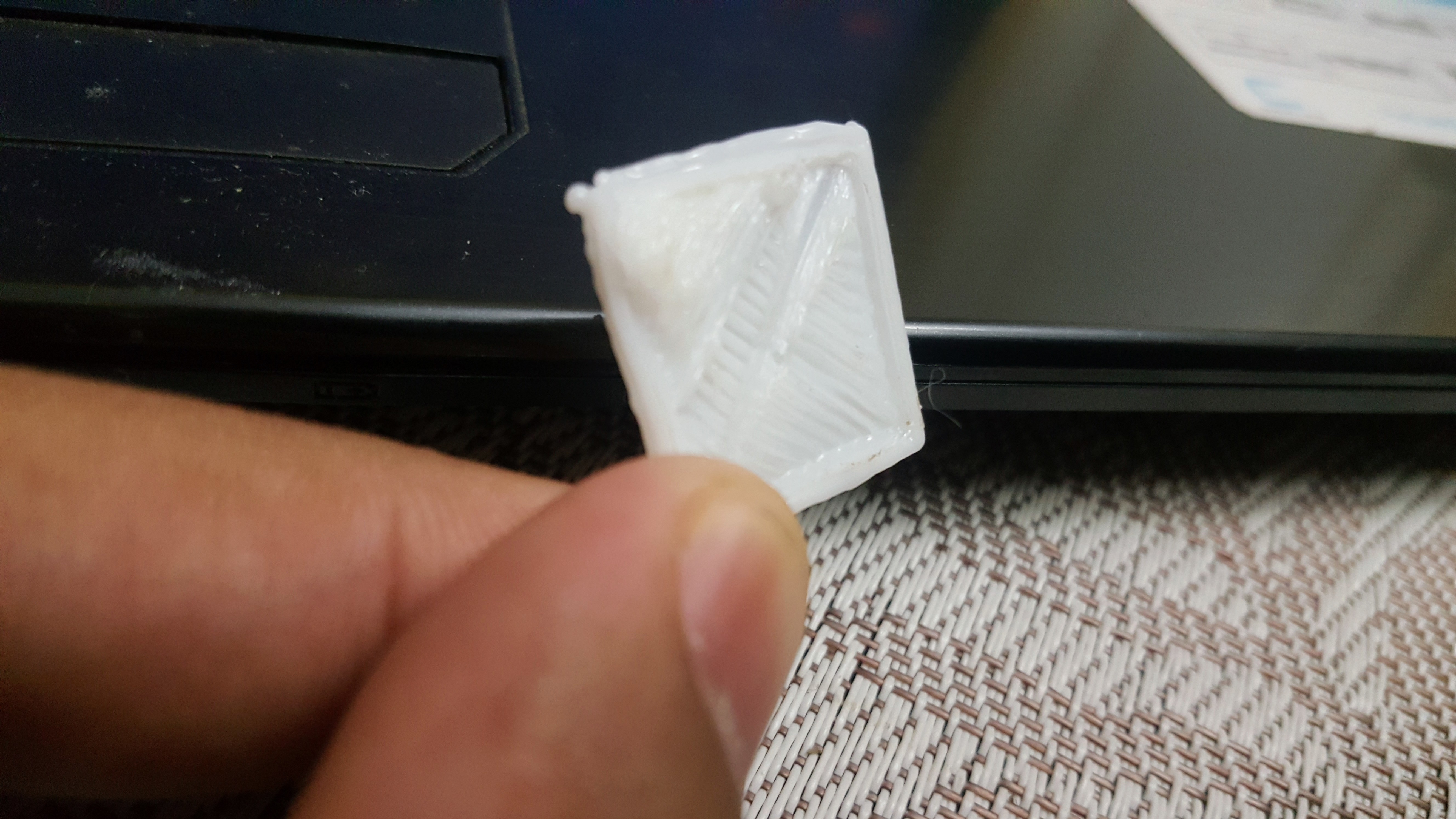
![]()
So the calibration cross that I thought was good was actually overextruded. The correct width of the line was supposed to be thinner like the one on the right. Putting in the correct values solved the issue and actually made all my prints better!
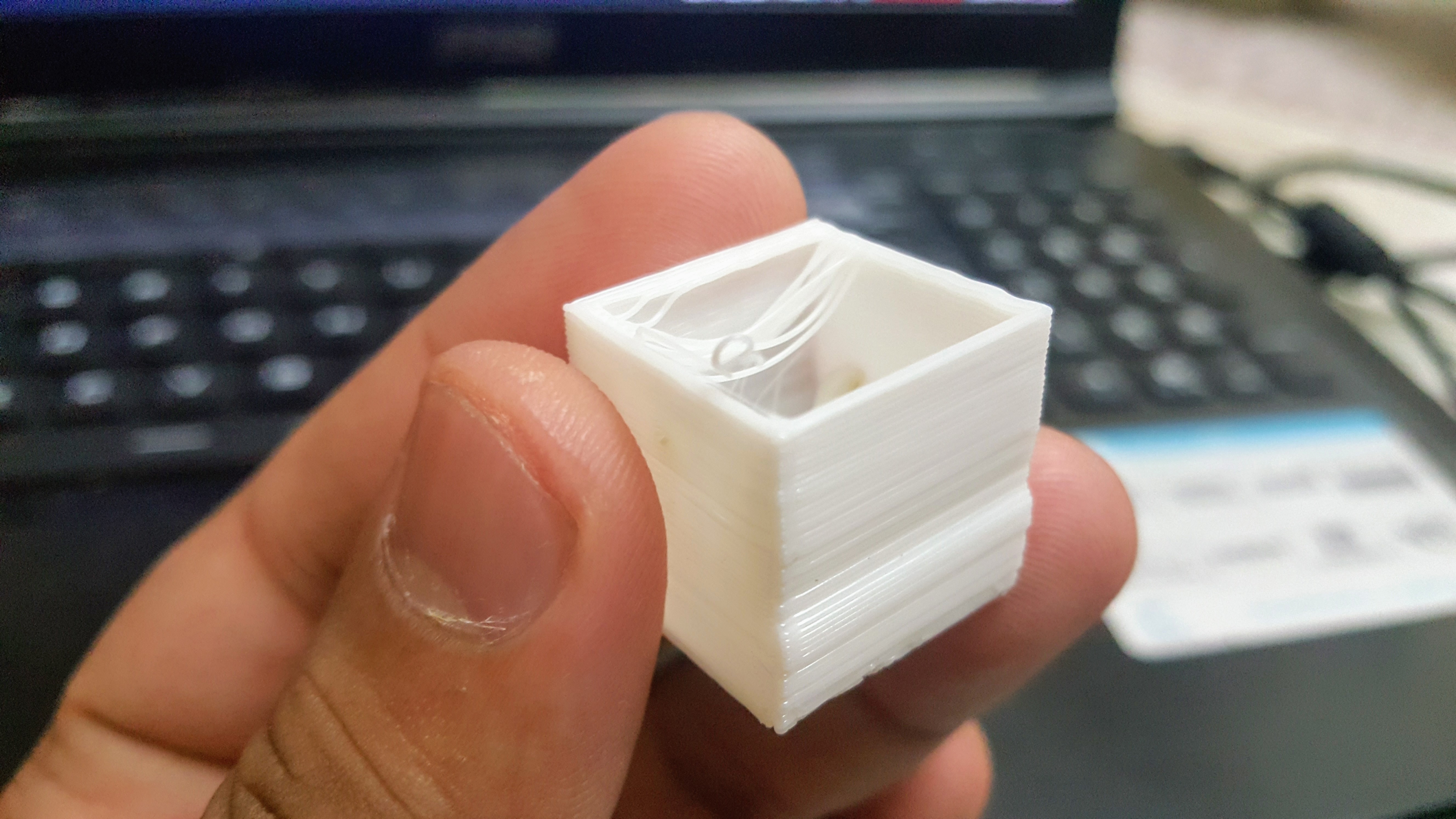
If you would look at the first picture in this post, it's obvious that there's still a lot to be done. One obvious one is the failed placement of the top part of the hollow cube. I think it has something to do with bridging which I think is already a difficult problem to solve. I also need to figure out why some Y layers were displaced resulting in a slightly skewed vertical wall. The hotend also oozes out extra filament which eventually drops onto the print and causing problems.
Having gone through all of the above, I now feel confident that there would be less difficulty in fixing the machine if any problems arise in the future. I guess this is what it feels like to be intimately connected with a machine.
-
2019-04-16
04/17/2019 at 05:04 • 0 commentsToday I focused my attention on making sure that the printer can properly draw an image onto paper using a pen. I figured that this is an important step that would help weed out problems early. And it did. Lots of them.
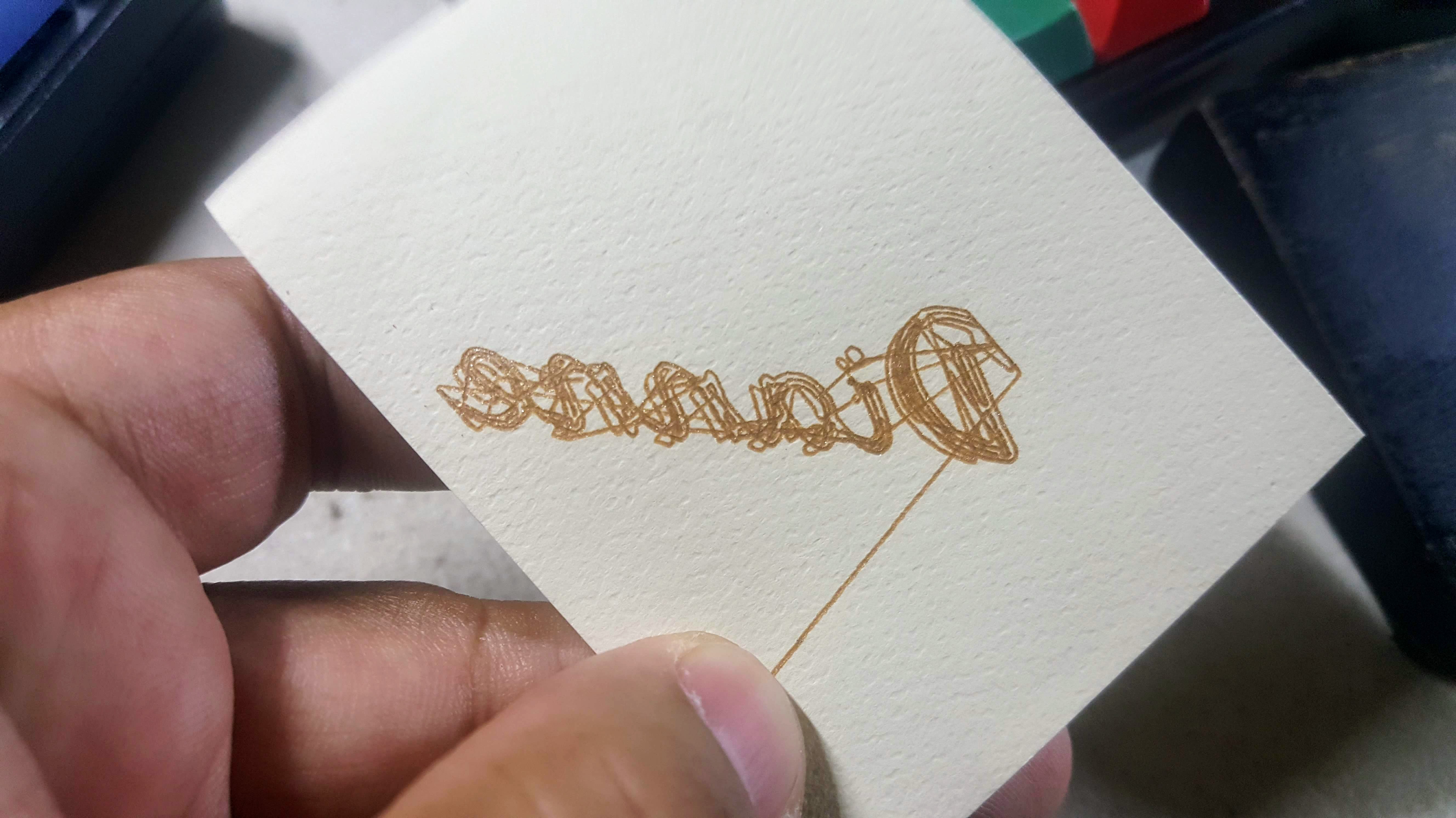
One problem that I noticed late was that one of my axes are actually flipped. It was only when I tried printing a word did I notice it.
![]()
That's supposed to read "Dianne".
This was easily fixed by changing a setting in firmware that sets if an axis is inverted or not.
You will also notice that there are extra lines that the printer draws to get to one point to the next. These are supposed to be non-print lines where the hotend does not extrude filament. Since I'm using a pen I had to manually add gcode before and after these non-print commands to raise and lower the pen when needed. The solution worked beautifully but is useless once I do use an hotend.
---------- more ----------Another problem I had to deal with was leveling the bed. My design doesn't have a fancy auto leveling system so I'm doing everything manually. This meant checking all four corners by eye with the aid of a magnifying glass, and adjusting nuts and bolts all over just to get the perfect level. It's frustrating but is satisfying when the expected results are met.
It took a lot of time, ink, and paper but it was all worth it. Watch the machine print out "Mahal kita, Dianne", it's Tagalog which translates to "I love you, Dianne" in the video below (Pardon the cheesiness, I want to impress the missus :P)
You will notice though that the printing head moves all over the place. This is because the file I used to make the gcode is not optimized for printing as a 2D image. Will try to look for an optimized image to print next time.I learned a lot from this step which made me more confident when the time comes that I actually need to use a hotend. Which is what I'll be working on next.
-
2019-04-12 to 2019-04-15
04/14/2019 at 20:36 • 0 commentsHad a good weekend full of progress.
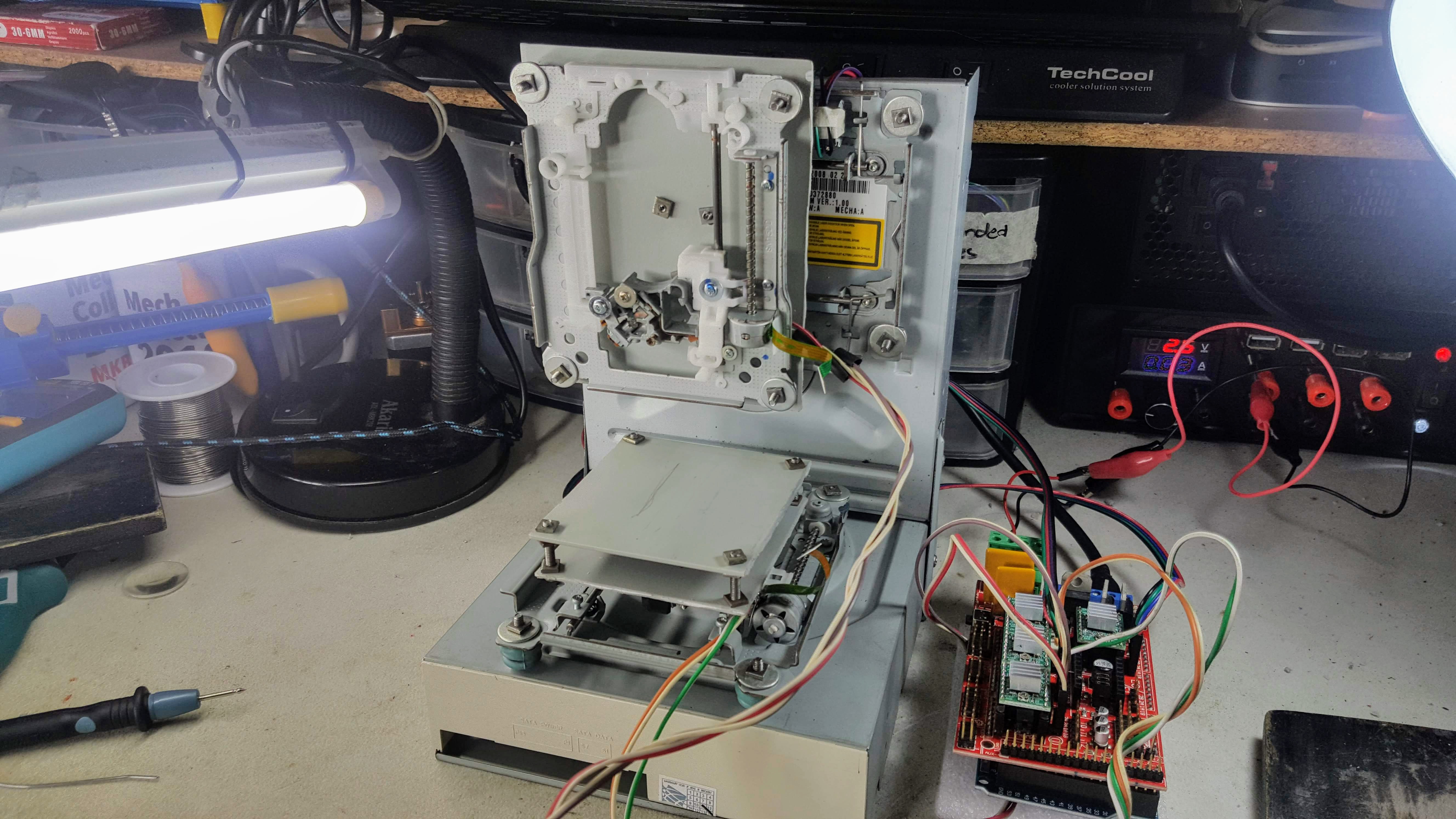
I was able to install all 3 axes. Which means the thing now looks like a proper home made 3d printer.
![]()
The printer can now also draw an image on paper. The resulting drawing is crude but the thing works.
---------- more ----------Getting the axes to move actually took me awhile to figure out. Turns out the RAMPS 1.4 board won't run execute gcode if no extruder is present. I had to do some modifications to Pronterface and the firmware just so I could temporary disable it.
I also had to disable endstops in the firmware so I could make full use of the limited print bed space as much as possible. I also lowered the movement speeds which helped a lot in the resulting quality of the print.
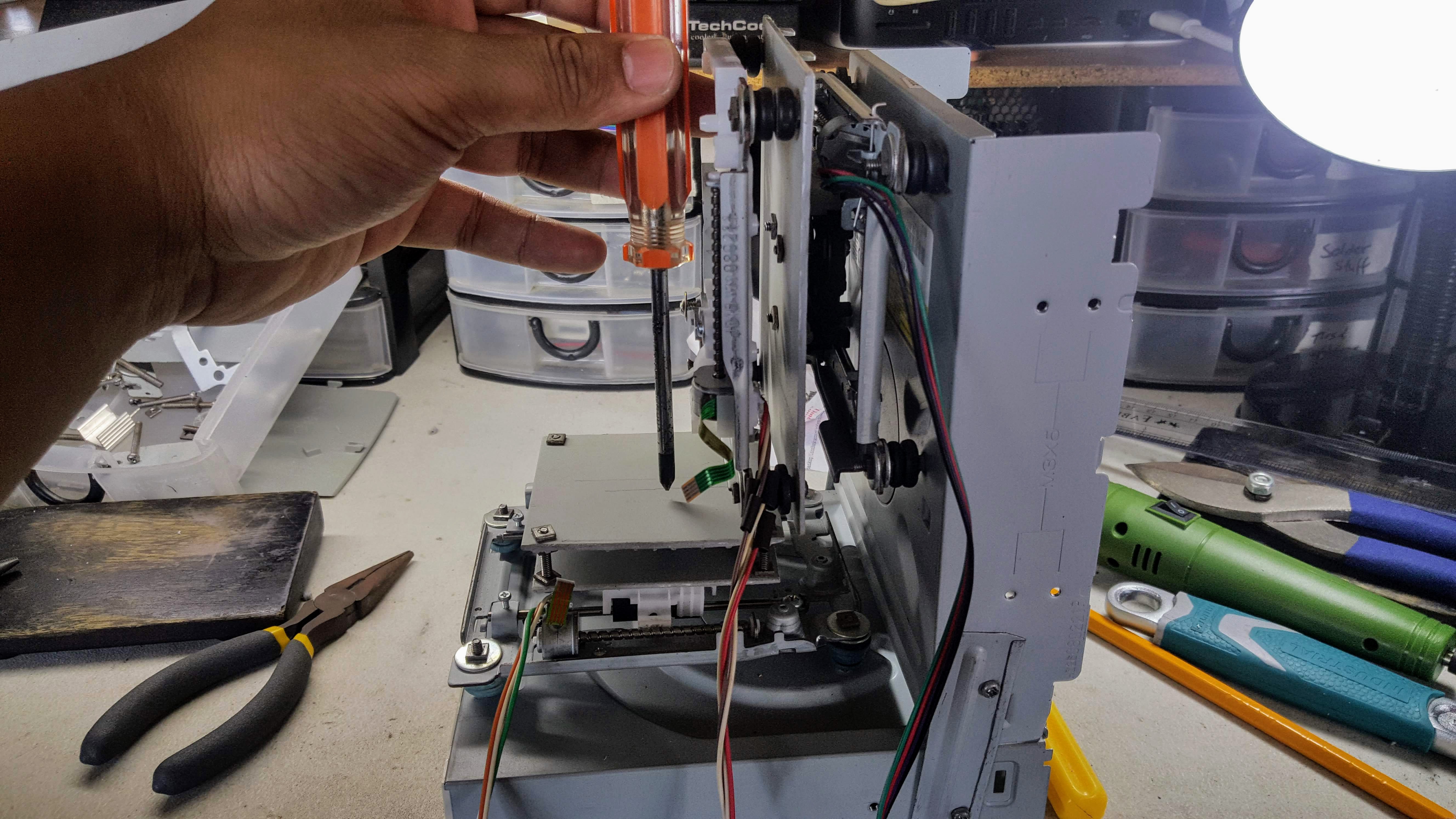
It became apparent later on how important the spacing of the axes are. As you can see in the image below the X and Z mounts are protruding a lot from the back case effectively making the print area smaller.
![]()
Thankfully, it was easy to adjust everything by altering the nuts an bolts. I had to do a lot of trial and error though but it all worked out in the end.
A big chunk of my time was spent calibrating the printer so it could draw properly. This meant making sure the bed is level, adjusting the print speed, changing values in the firmware configuration, fiddling with Slic3r settings, and lots and lots of testing. There were a lot that I just don't have the time to outline each in detail. I might in the future.
Up next: Mounting the hotend!
-
2019-04-11
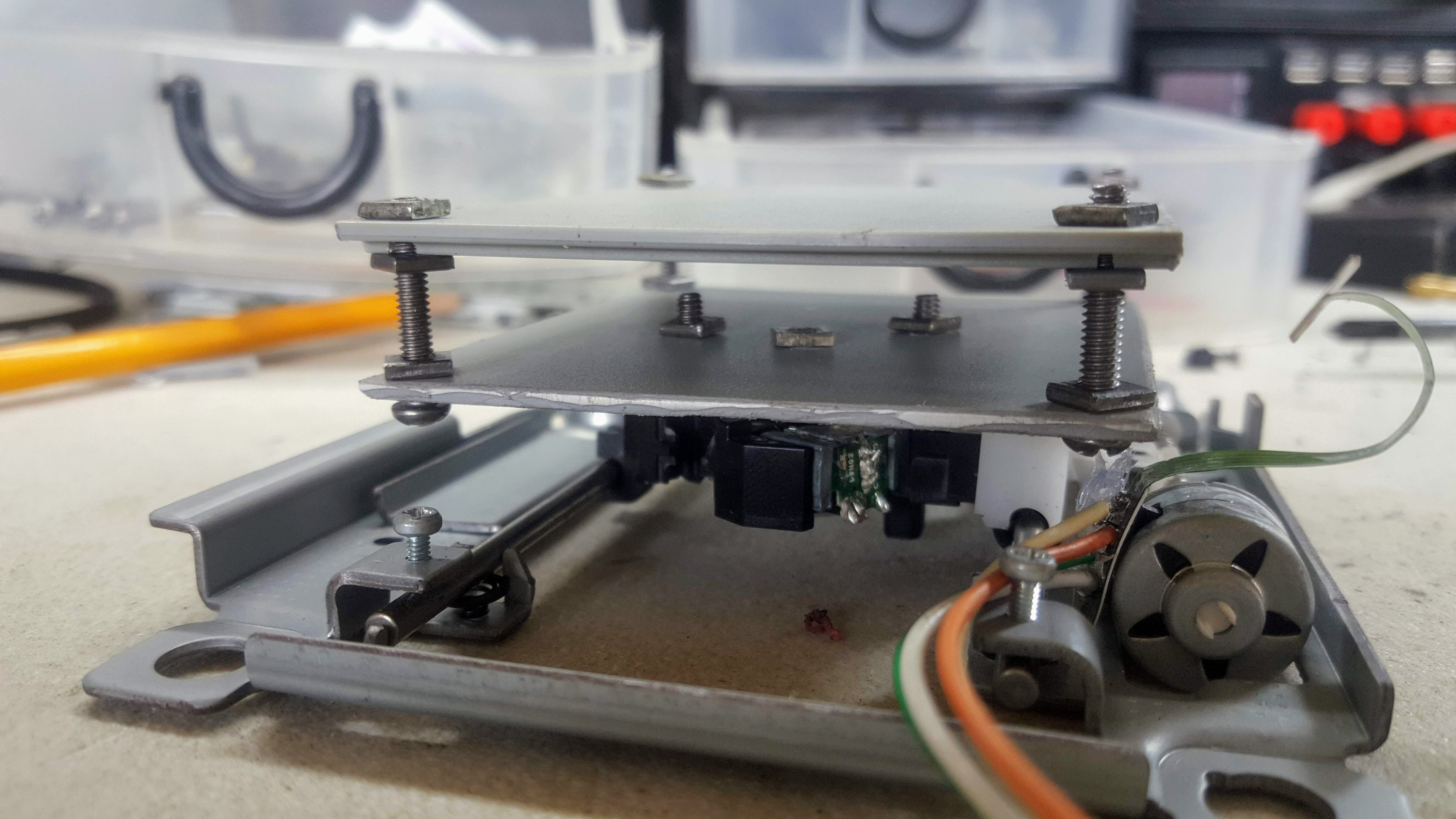
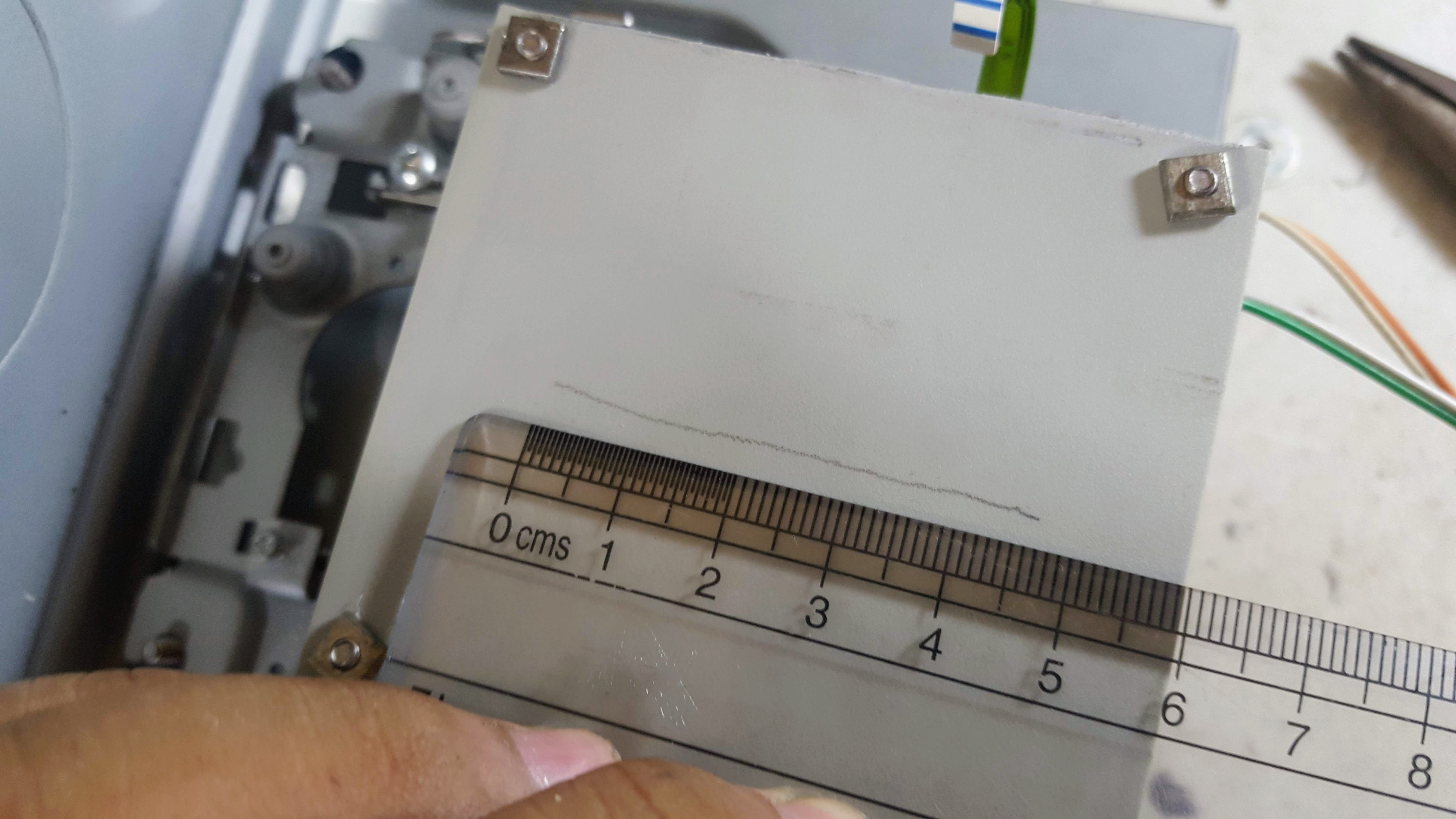
04/11/2019 at 08:11 • 0 commentsI decided to work on the print bed today so I could measure and estimate just how big my print dimensions will be.
![]()
I salvaged the plastic sheets from the inkjet printer I dissembled a few days ago. I will be replacing this with acrylic in the future but this will do for now.
Initially I was planning on using motherboard mounts but I found that the bolt and screw method I have been using to assemble the frame works great here as well. This approach works well as I can easily adjust the heights of the corners by twisting the nuts. This will be very helpful once I start leveling the print bed.
I just estimated the positioning of the print bed while making sure that it moves freely without hitting the frame or other parts. If things go as planned I should have a maximum print dimension of around 45mm x 45mm. It's very small but is expected out of this kind of home made 3D printer.
![]() ---------- more ----------
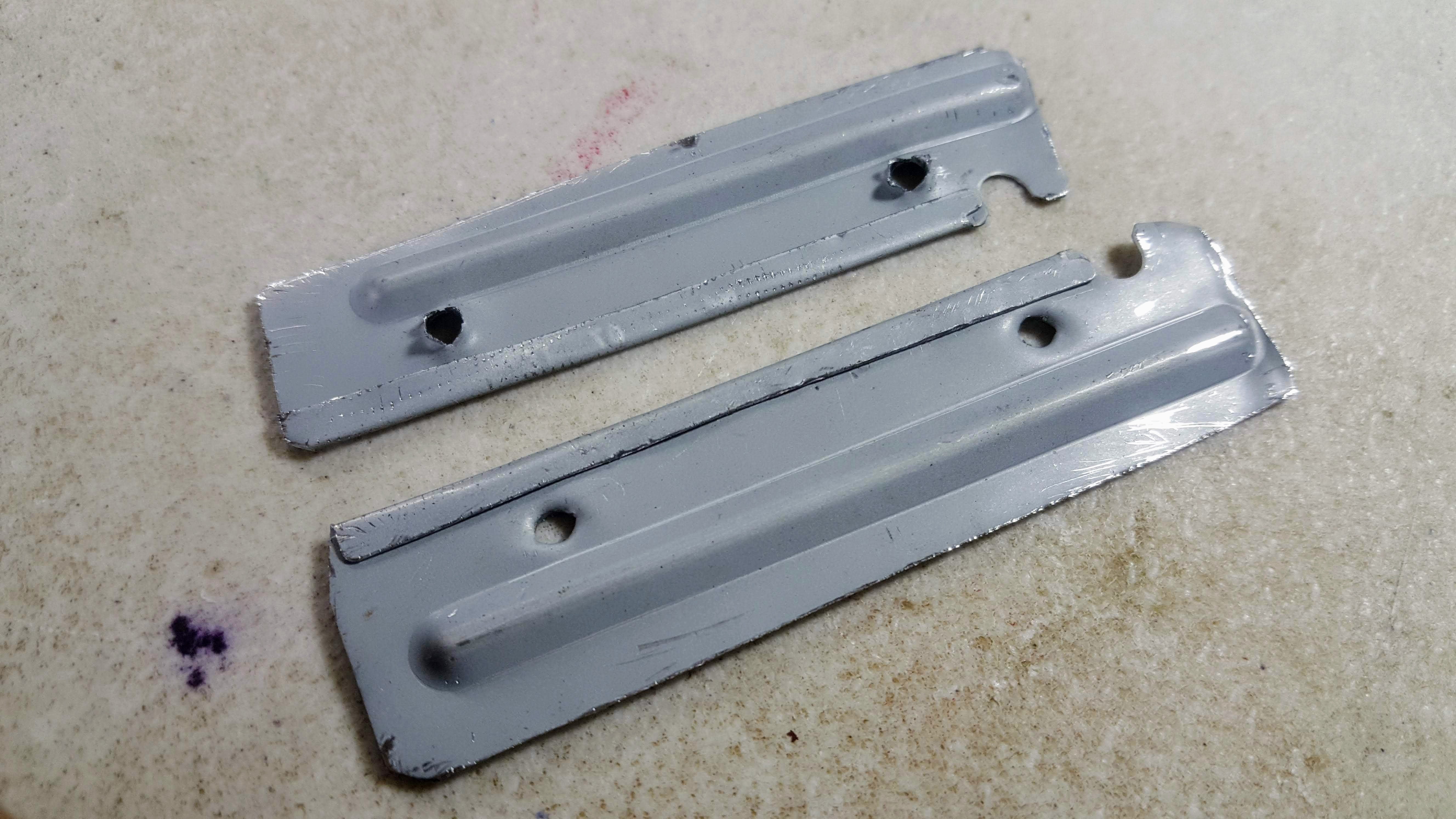
---------- more ----------I also worked on making the frame more stable. I did this by adding braces to the sides made from cutting a long strip from a CD-Rom casing. The casing is actually soft and bends quite easily so it's not really an ideal brace. To strengthen these I employed a technique of folding the edge to make it stronger. See picture below. I am surprised how strong it became from just a simple fold. I learned this from watching an actual blacksmith make an armor out of aluminum sheets.
![]()
To make the whole frame even more stable, I reinstalled the plastic housing initially found inside the CD-Rom casing. This made the frame heavier and sturdier as can be seen in the video below:
Up next: I'll be mounting the other axes, and after that slap on a pen and see if this machine can draw. Stay tuned!
-
2019-04-10
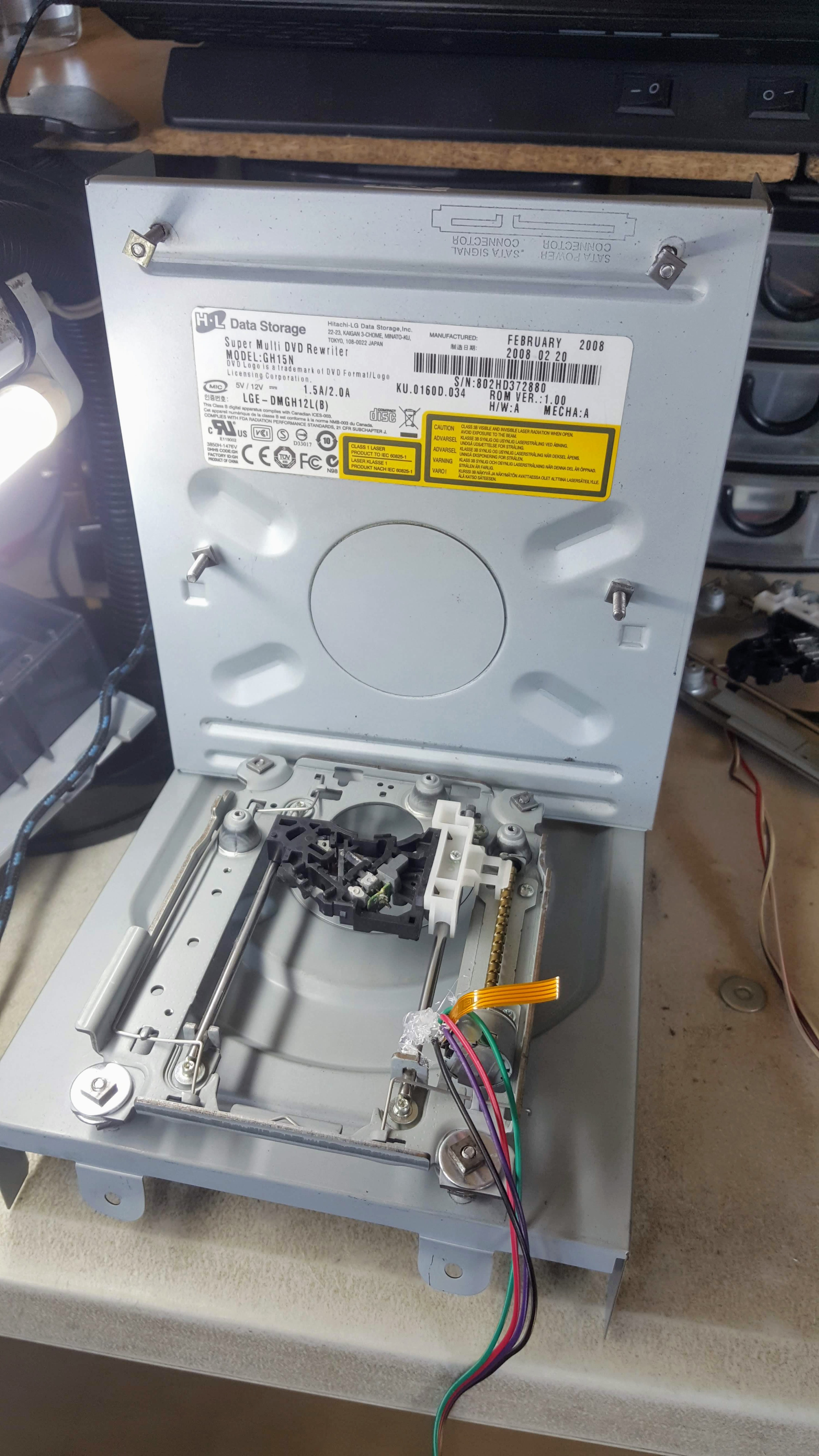
04/10/2019 at 13:26 • 0 commentsToday I worked on setting up the frame and mounting the drives. I only had time to mount the Y-axis though
![]()
Since I did not have a drill powerful enough to punch a hole through the thick metal case of the CD-Roms, I opted to go old school by using a nail and a hammer. It's not pretty but it did the job.
![]()
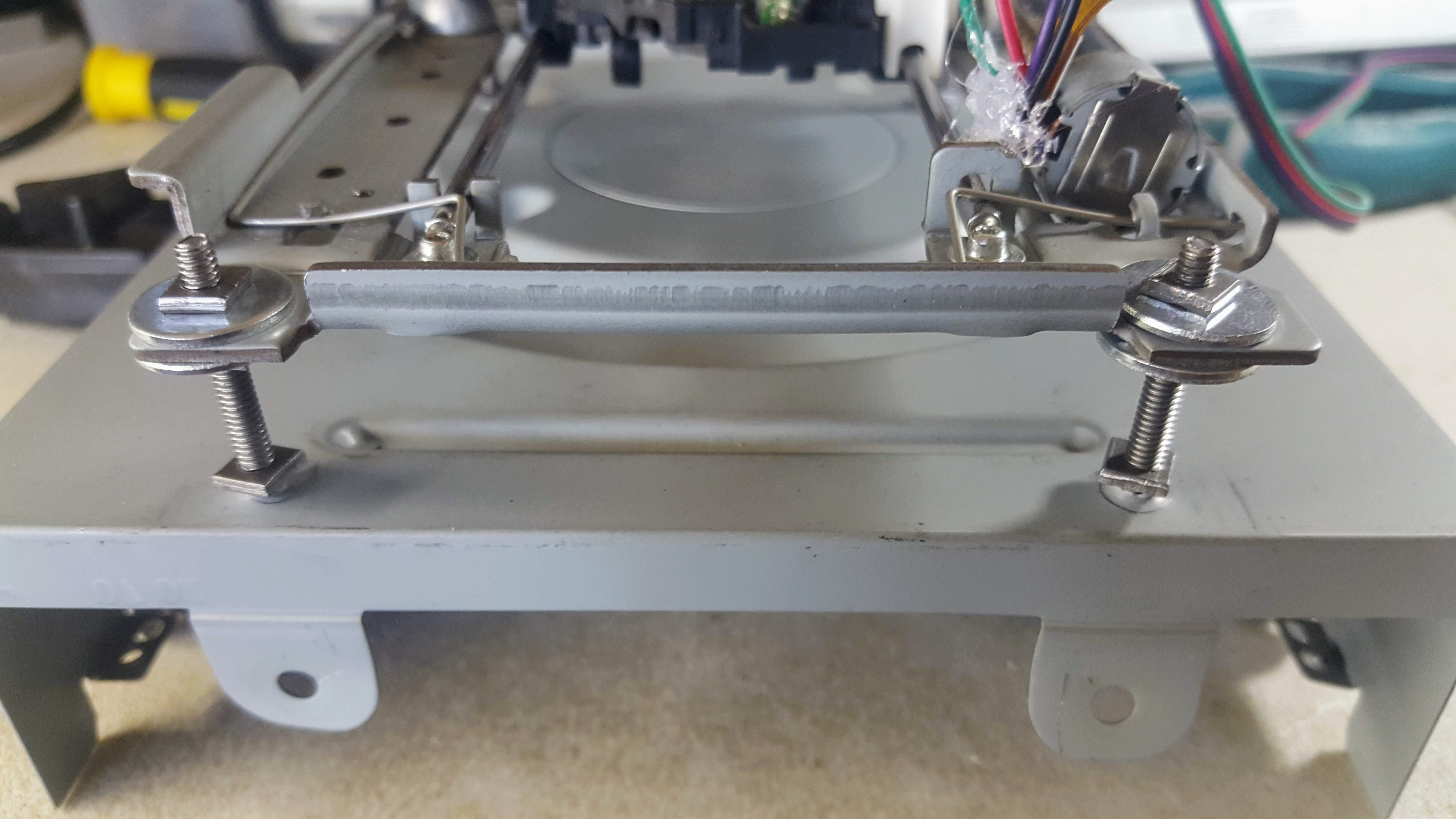
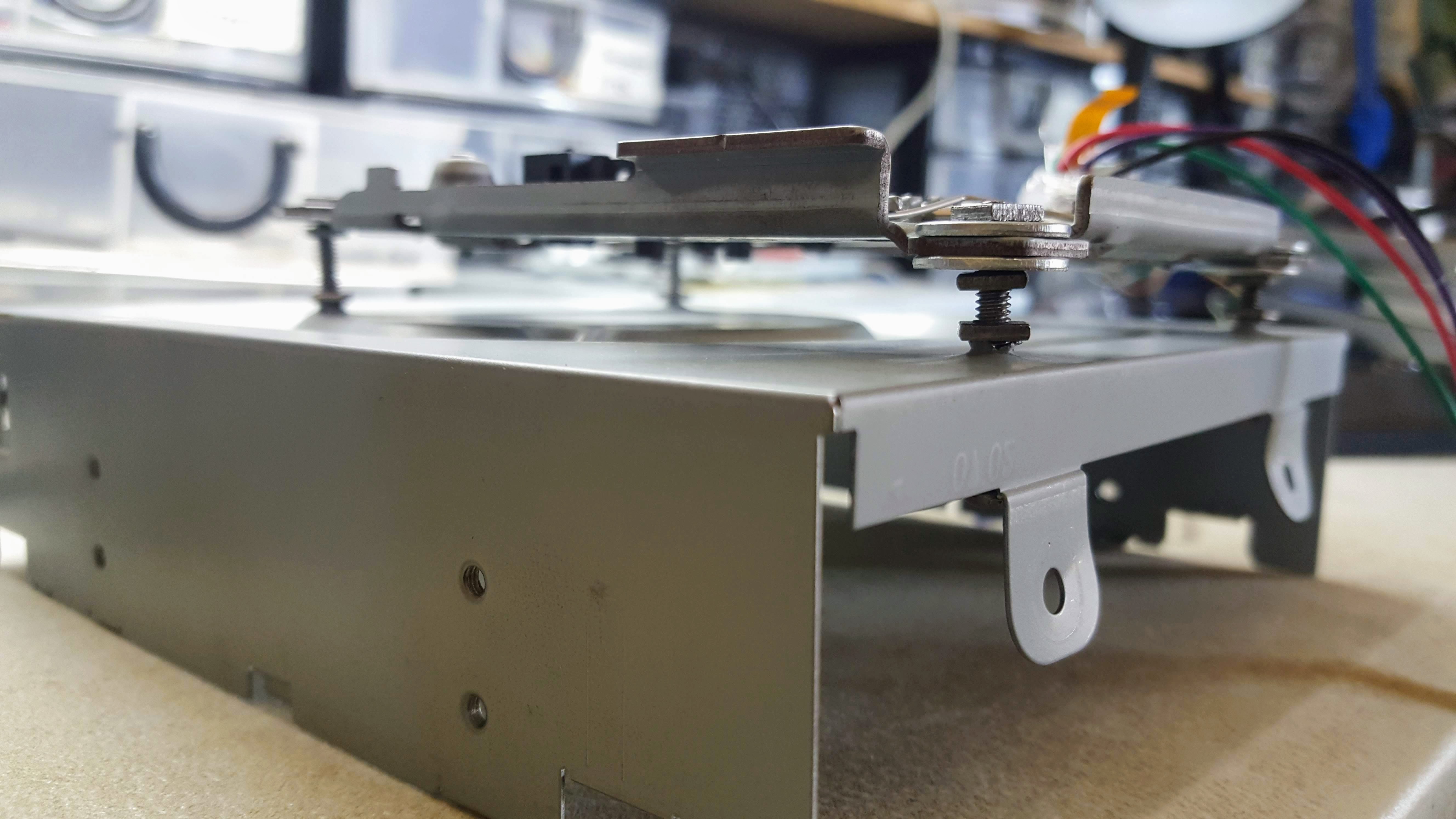
The bolts that I had on hand were too long that it made the height of the mount too high. I did not want to buy new bolts so i had to improvise by extending the bolt downwards under the case and adding an additional nut to hold it in place. Thanks to this trick the mount is now lower giving enough space for Z axis movement.
![]() ---------- more ----------
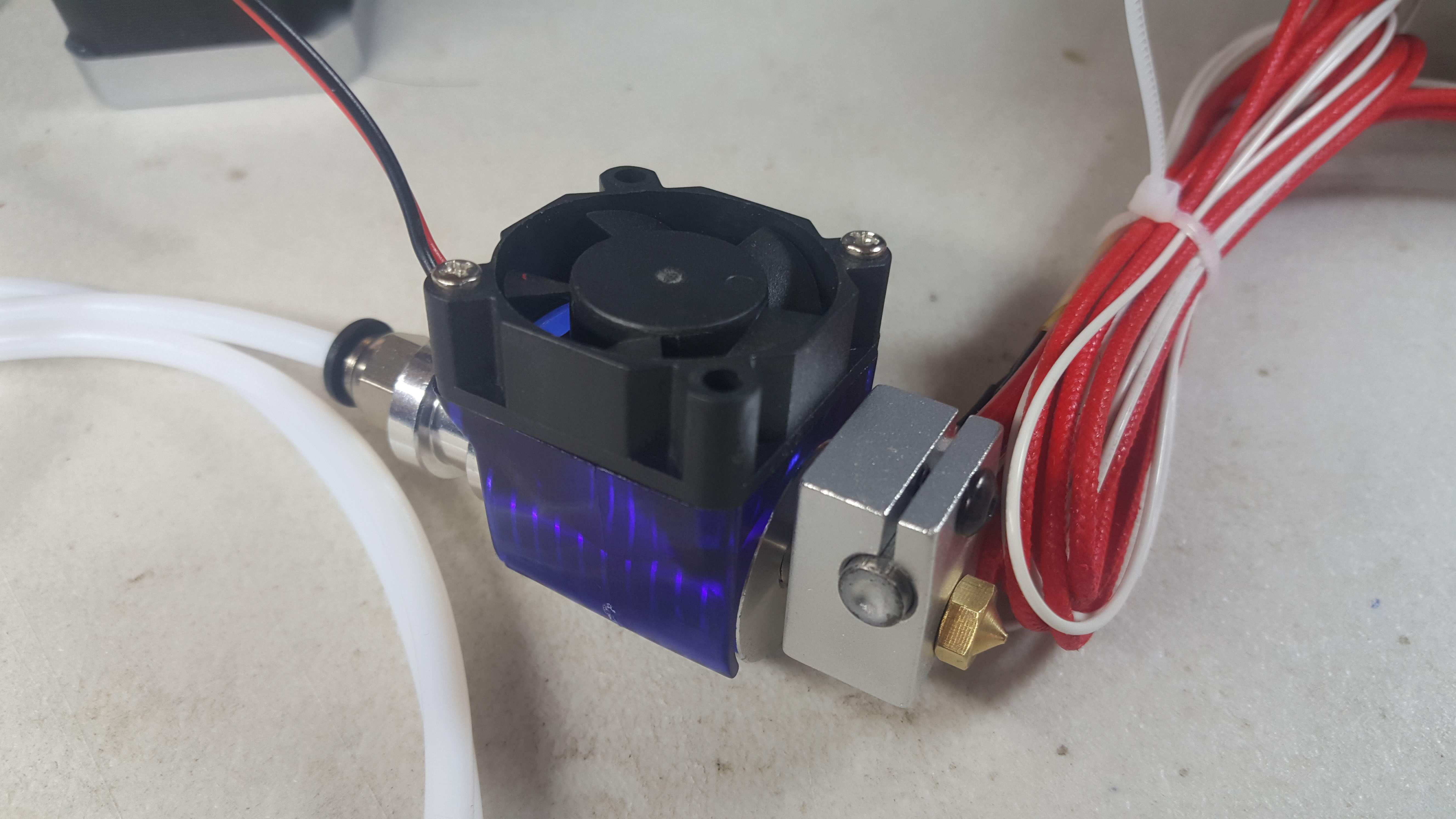
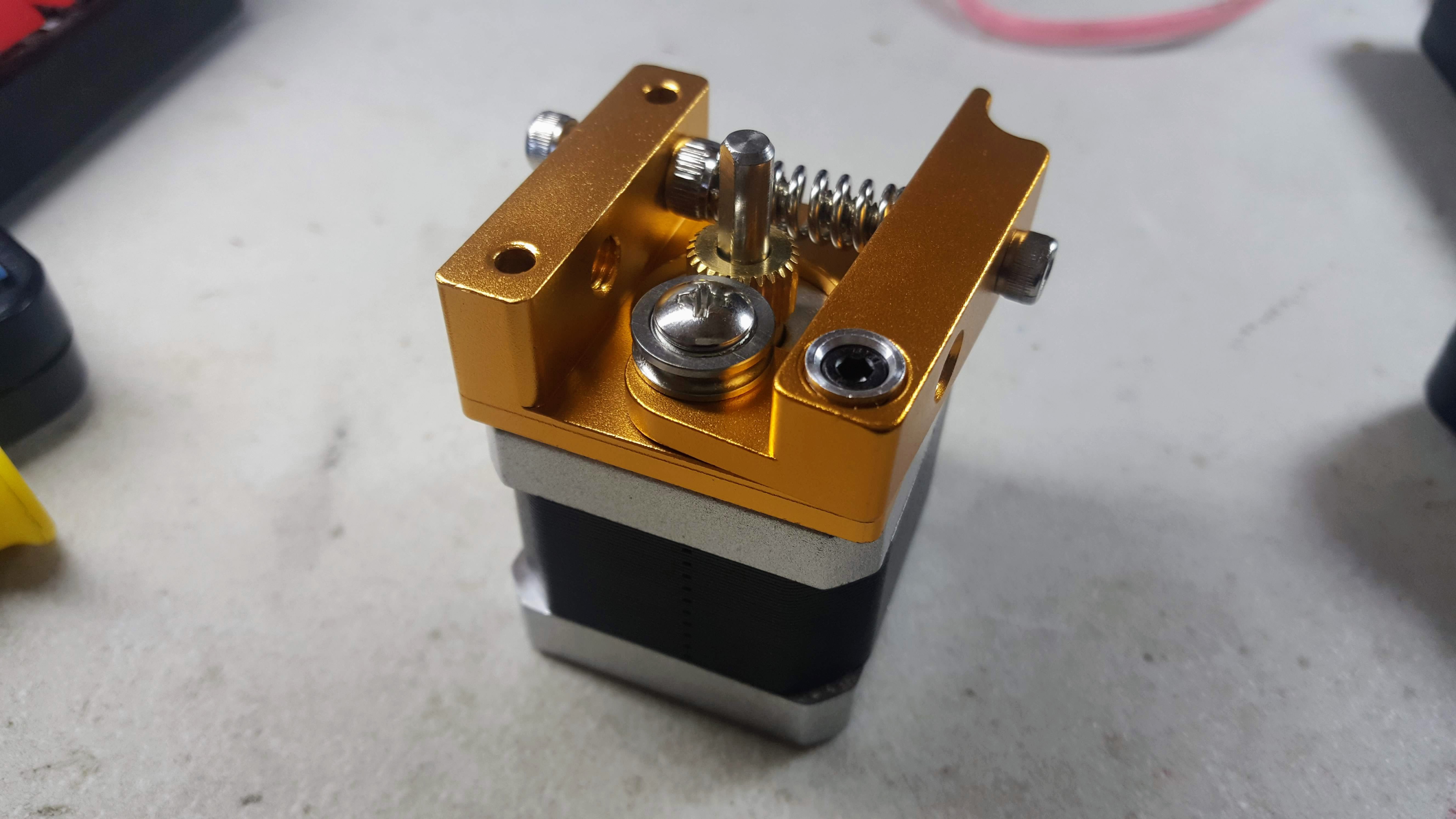
---------- more ----------Aside from mounting the drives. I also took the time to assemble the extruder frame and hotend that I bought. I had to do it early to make sure the parts are complete. Thankfully, they are.
![]()
![]()
I can't test them yet because I need to finish setting up the mounts. Crossing my fingers that I was not sent defective units.
Next step: Making the frame more sturdy with braces and mounting the other axes. Stay tuned!
-
2019-04-09
04/09/2019 at 12:58 • 0 commentsToday I was able to hook up all the stepper motor axes and the extruder motor to my RAMPs board.
Connecting them involved a lot of soldering which took some time because the leads of the stepper motors were too near each other that I needed to be careful that the wires didn't touch.
Once hooked up, I noticed that the Z axis was moving way more slowly than the X and Y axes. I later learned that, by default, the Z axis has a different steps per unit value. I assume that this is because the Z axis operates differently because this is where hotends are usually mounted.
After changing the settings and a lot of trial and error, I was able to finally make all motors moved from Pronterface as shown in the video below:
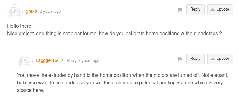
---------- more ----------I'm still refining my workflow when testing the motors. This is made more complicated because I still do not use endstops. Currently what I do is that I manually move the stepper motors to their home position, power up RAMPS, and then send a home signal command. It's a bit of a pain so I will look for a better workflow in the future.
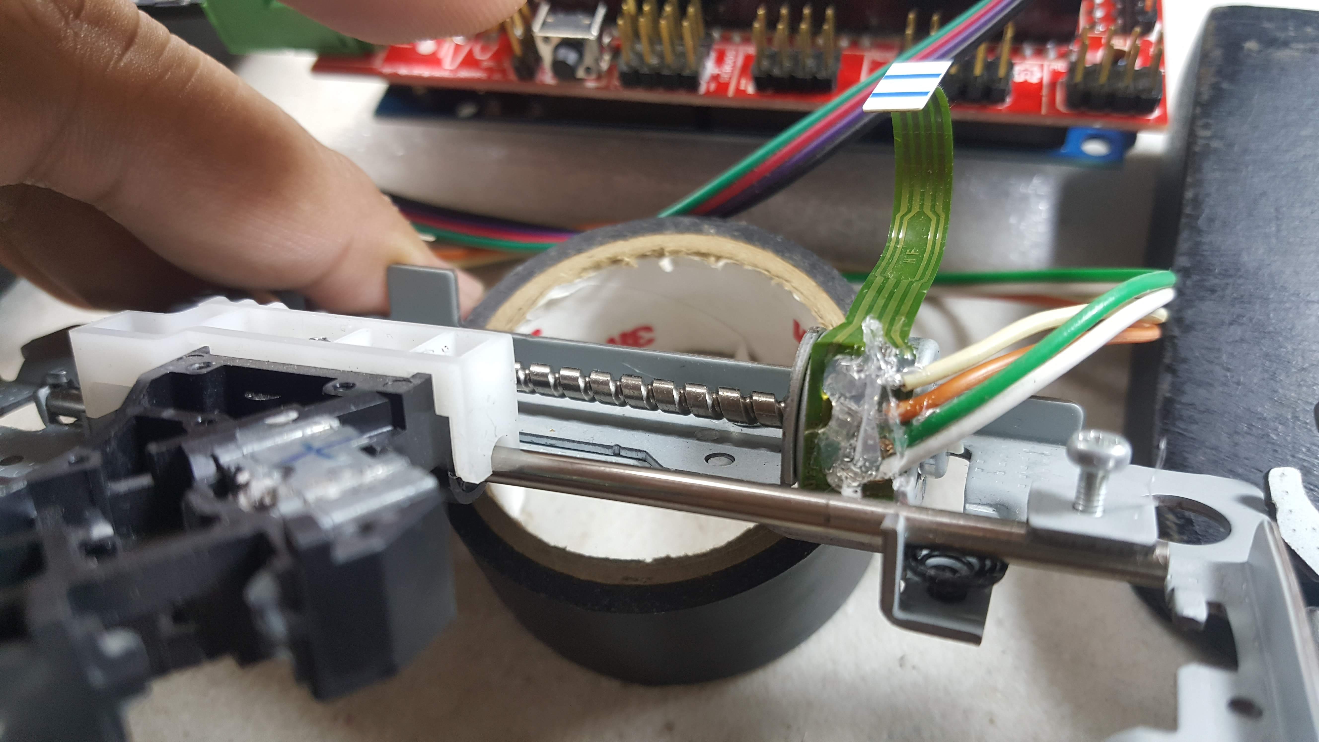
There was also one time when one axis stopped working because of the wires got loose and touched other leads. To fix this, I placed hotglue on the wires to make sure they stay in place. It's a neat hack I learned from this video.
![]()
However, I am a bit worried that the heat from the constant use of the stepper motors might melt the hotglue but we'll see. If this happens then I have no choice but to redo them and think of a better way to avoid such a thing from happening again.
I've made good progress today. My next step is I'll be hooking up the hotend and also install the extruder frame on the NEMA 17 stepper motor. Stay tuned!
-
2019-04-08
04/08/2019 at 15:44 • 0 commentsThe very first thing I did was I opened up my old printer and scanner to see if I could use their motors and rails for my 3D printer similar to this instructable.
![]()
I was disappointed to learn that only the scanner was using a stepper motor. The two motors inside the printer were both DC motors. This means I'll have to go with CD-Rom drives for now and just switch to scanner and printer parts once I am in need of a bigger print area.
I wanted to make sure that the electronics that I purchased were working so I concentrated my efforts on making a single stepper motor move. So I hooked up the RAMPs board with the Arduino Mega, uploaded the Marlin firmware, and then sent commands to the board using Pronterface. The motor responded by turning a bit and then went back to it's original position. This is not the correct behavior so I continued sending commands just to see if it would do anything else. It did in the form of an overheating motor. It was so hot that it was enough to burn the skin.
---------- more ----------![]()
This is when I remembered a helpful tip from this instructable (See step 6) about current intensity regulation. Turns out I needed to limit the current that is sent to the motor to avoid it from overheating. I followed the step and it seemed to have fixed the overheating problem.
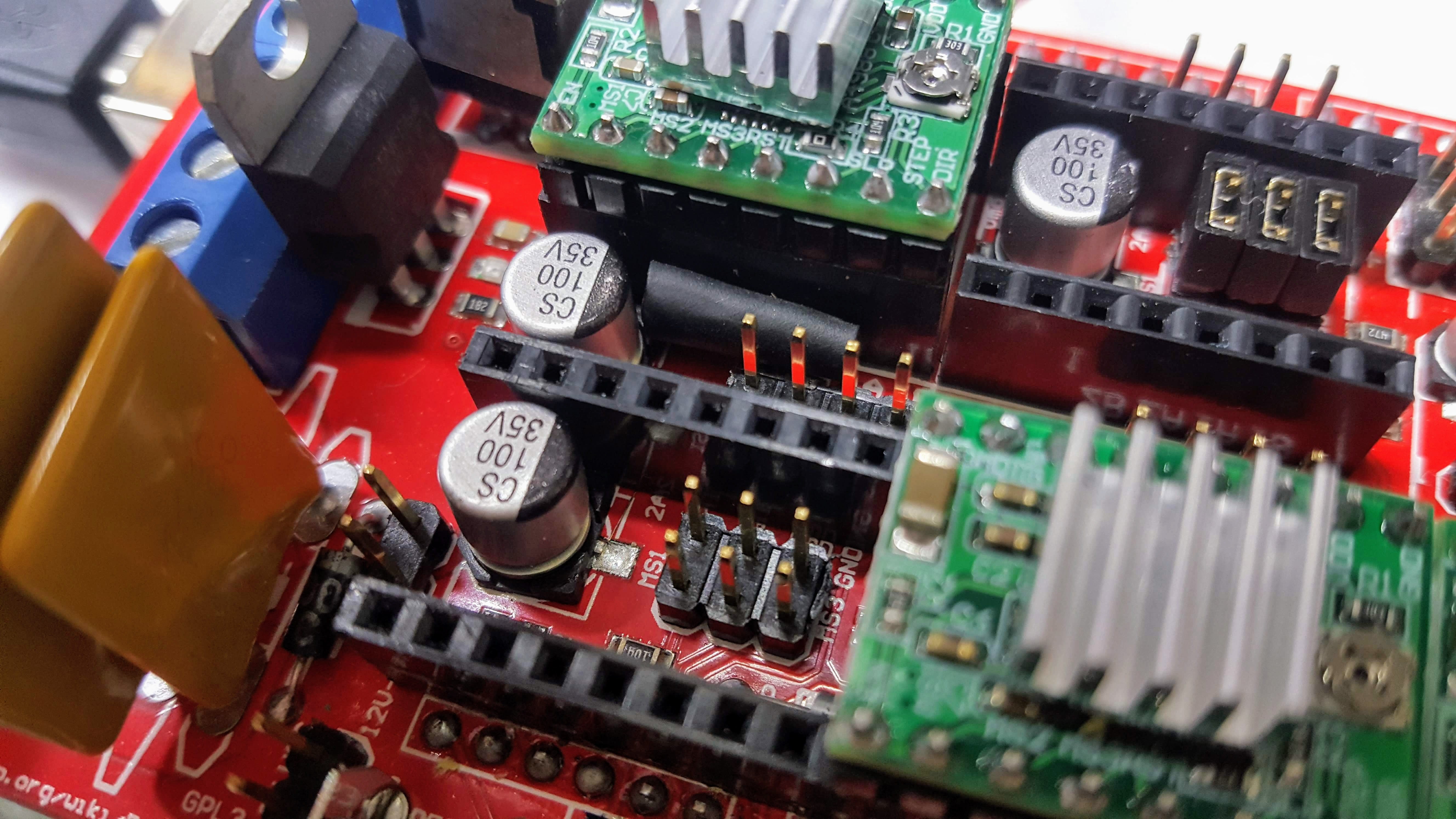
The motor was still not moving though. After a long time of searching I learned that I forgot to install jumpers onto the RAMPS board to enable micro stepping. Turns out some boards have these jumpers already installed. I got the jumpers in a separate bag which meant I had to install them myself. I followed the instruction found here on how to insert the jumpers and it did the trick!
![]()
The motor was now moving. But only in one direction! Turns out I needed to move the rail to the home position manually and then send a Home signal from Pronterface. After doing this my motor can now move forward and backwards as can be seen in the video below:
What about endstops? Where do they come in? I thought it was weird that the tutorials that I was following did not use endstops at all. According to the discussion here, endstops can still be used but the printing area would be reduced even further if they are used.![]()
I'll have to research more about this. For now, I'm just happy that I was able to reach the goal of making a motor move.
Up next: Hooking up the other motors from the Y and Z axis, the extruder, and the fan while making sure that the board survives if run for an extended period of time.
-
Project Resources and General Planning
04/07/2019 at 04:23 • 0 commentsThis project was inspired by various people who has had success making their own version of home made 3D printers. I am fortunate that there is now a wealth of resources and tutorials that I could follow. Without them, I doubt I would have attempted this.
I'm listing them all down here with short descriptions as to why and how they are helpful and important. I am hoping that this would be of use to others who want to take on this project as well.
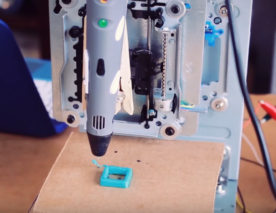
- Tinkernut's Project - Video and text version- The video that first taught me about the possibility of a cheap 3D printer. Uses Arduino UNO, 3D Printer Pen, and A3967 Stepper Motor Driver. Here's an updated version of this project with a different approach.
- Electronic Grenade - Based his project off Tinkernut's. Goes through the steps in more detail.
- EWaste 60$ 3D Printer - Different from the first two by using RAMPS 1.4. This is also the only one that teaches about current intensity regulation to avoid overheating stepper motors (Check Step 6). Everything else is also good albeit a bit dated with broken links to important files.
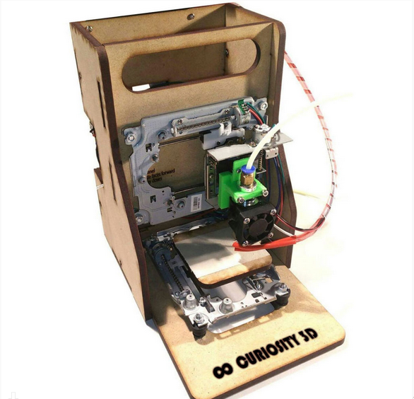
- Curiosity 80$ EWaste Educational 3D Printer - Similar to the EWaste 60$ Printer, this one is more detailed and easier to follow. as it is also targeted towards younger aspiring makers.
- Joe Clinton's Project Log Playlist - A video playlist of a 3D printer from start to finish based on the Curiosity 3D printer. Starts with testing the circuits first before mounting the drives. It's a nice glimpse of what pitfalls to expect and avoid throughout the project.
- RAMPS 1.4 Assembly Guide - Simple guide on how to assemble your RAMPS 1.4 board. This is crucial as some purchased boards may require some assembly.
I'll be basing my project using the lessons from all the links above.
Initially, I was planning to go with Tinkernut's approach (Arduino, 3D Printer Pen, and A3967). I had concerns about the print quality though so I asked Tinkernut and he replied that more fine tuning needs to be done with the code and that the the 3D Printer Pen's extrusion is too thick to have a good resolution print.
![]()
The Curiosity project, on the other hand, uses Ramps 1.4 which is a commonly used controller board. I'm going with this just because I feel there's support for it if I run into problems. I also bought a hotend and an extruder similar to what others had success with.
![]()
As for the frame, I might go with the simple approach of using the hard drive cases similar to Tinkernut's. I actually like how Curiosity looks but I don't have the necessary tools to make them.
I think I have everything thought out. There are still some small issues that I am unsure of but I bet I can solve them as I go along.
Next step is setting up the Ramps 1.4 board and hook it up to all the drives just to see if the electronics are working properly. I'll make a new log about it soon.
- Tinkernut's Project - Video and text version- The video that first taught me about the possibility of a cheap 3D printer. Uses Arduino UNO, 3D Printer Pen, and A3967 Stepper Motor Driver. Here's an updated version of this project with a different approach.
Poor Man's Mini 3D Printer
3D Printer using upcycled CD drives, hard drives, and an ATX power supply.