-
Cooling issues
06/11/2017 at 20:41 • 0 commentsLast time when I tested the stepper motors all next to each other next to each other the motors turned very hot to a point where I nearly burned my hand.
That made me realize that the current cooling inside the PLA plastic may be even worse.
Danny already gave us an adapted 3D model where a fan was added to cool down the 3 geared stepper motors.
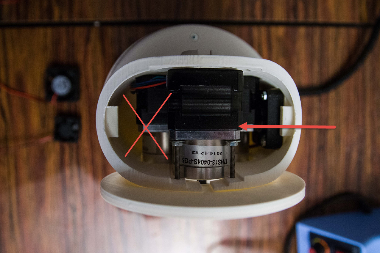
When I look at the solution from the top view then I see that the solution does cool down the center and right motor but no air gets at the left motor. So that one may overheat.
![]()
Also this ventilator it does not solve the cooling of the stepper motor below in the base. since the hot air will go up not down.
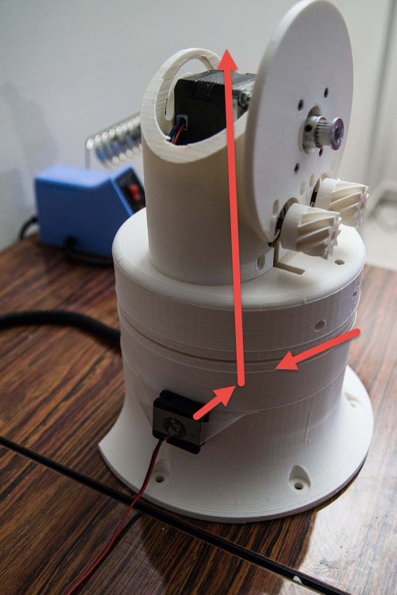
That means that I have to drill a hole in the side of the base to cool its stepper motor which is actually the most powerful one. (Seen inside the hole to the left.)
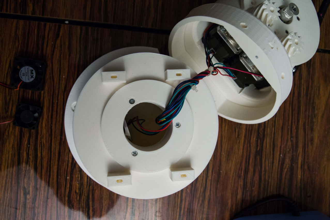
![]()
I initially thought that I would use one 40x40 mm ventilators to blow air into the base but it turns out that the base is too low to drill a hole for a 40x40 mm. So I have to resort to the 30x30 mm ones. They are more silent but also produce less air stream.
So it makes me think that I need 2 at opposing sides that drags in air and forces it upwards to the opening.
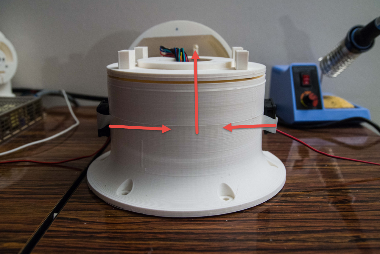
![]()
Air that is drawn in through the base and forced upwards now also will be forced in the upper stage and cool the 3 geared stepper motors on all sides so we can remove its ventilator.
![]()
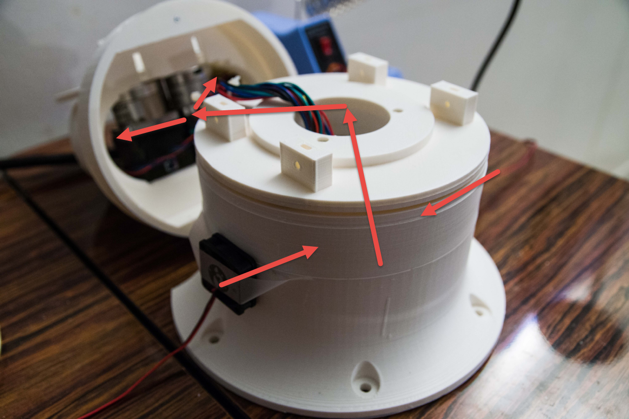
Another view how the air could be forced. Those ventilators could probably be mounted inside the base.
![]()
The only issue I have is the question if I put the ventilators in the 90 degree angle or in a tilted angle so it creates a vortex into the base. The goal is to cool the base big stepper-motor too.
If there is a cooling expert out there, then feedback would be appreciated. :-)
-
Testing the code quality- First step: Measuring
05/30/2017 at 21:06 • 0 commentsI am using a Saleae logic analyzer to test the code I develop. (This can be done with the $10 Chinese clone but realize that Saleae developed the software to make this possible. )
I need a few things to know. Especially because this is 3D printed cogs and material and any accuracy has gone down the drains.
So for the Thor control I need some measurements:
- How many micro-steps does it take to have one stepper motor full revolution?
- How many steps does the 5:1 geared stepper motors take for one full revolution?
- Finally, how many steps does the stepper motors need to move a certain angle?
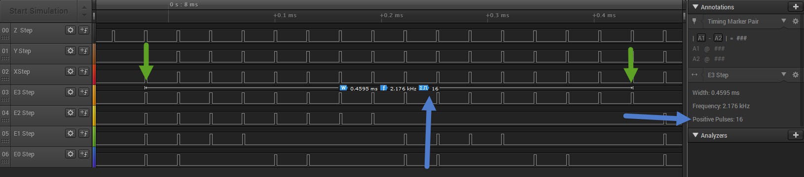
You go the measurement (right side) then you can define a range you want to measure on (green arrows)
You can now select if you want to count the positive pulses.
![]()
Example above shows 16 pulses.
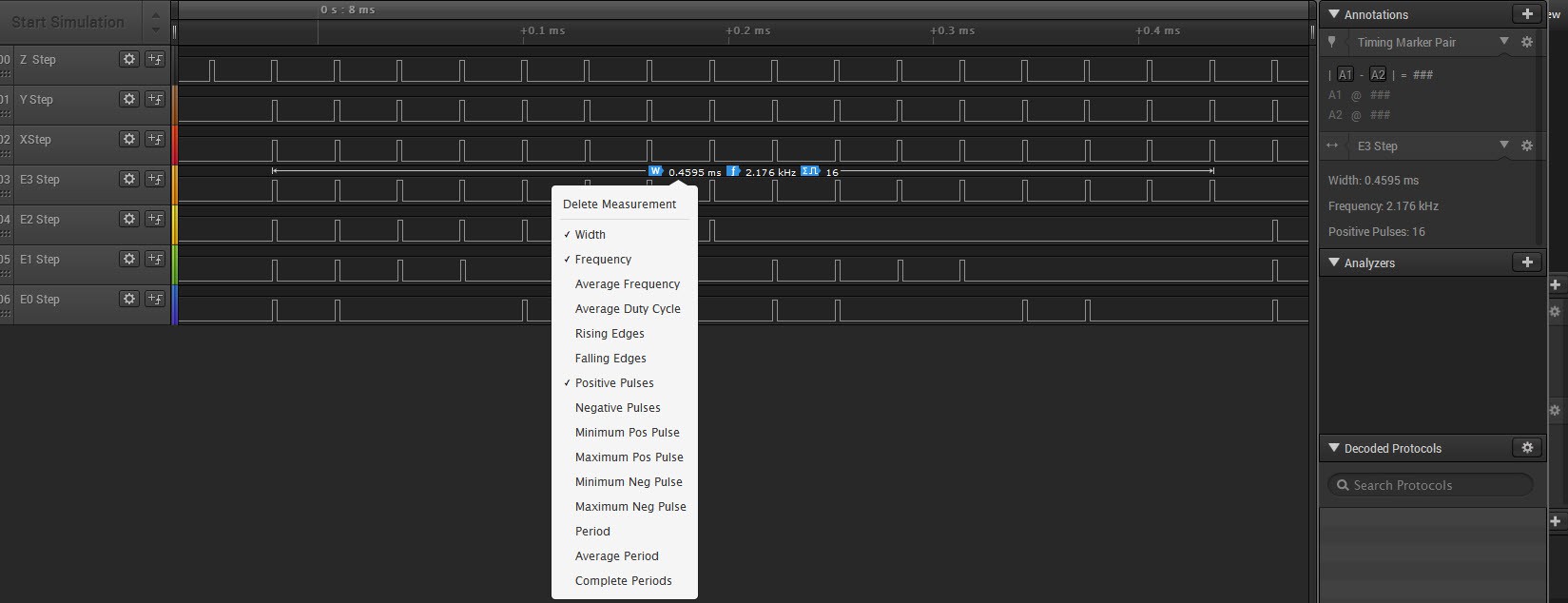
A list of possible options to choose by pressing right click on the time measurement line.
![]()
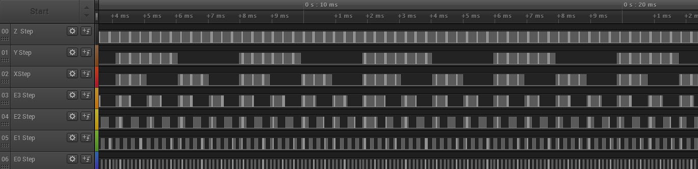
This is a very interesting feature because when I am going to steer the stepper motors, I want to be able to measure deviations. I want to know if the stepper motors behave as they should or if I have a software bug.
This counting becomes tricky when I start with acceleration and deceleration. This software will help. When you deal with robotics that deals with repetitive motion, then every step must be accounted for.
-
Brainstorm: The next steps in the software design
05/29/2017 at 20:55 • 0 comments
I on purpose do not look at other robot designs to create the software. The reason why I do this is to force my imagination to come up with my own design.I am at a stage where I can now move the robot. Up to 8 stepper-motors in parallel all in less than 3 µS per step. And extendable to multiples of 8 more motors in parallel if the need is there.
The question is:
- How do I feed the data?
- How do I take into account micro steps?
- How do I take into account gears?
- How do I take into account acceleration/deceleration of the stepper motors?
- How do I take into account inertia?
- How do I take into account imperfections in the mechanics and especially the 3D printed plastic?
- How do I take into account mass and inertia of the mass to be moved?
- How do you correct for errors using feed-back sensors?
Every single point above has an effect on how the stepper movement steps must be executed.
Big challenges ahead :-)
That is what I love :-)
Observations:
- When a stepper motor is "enabled", then it jumps to the nearest full step.
So this induces an error. - The motor can skip steps, when the acceleration of the load is too fast.
This induces an error
- A "disabled" stepper-motor does not use power.
However do not stand under the load! - A "disabled" stepper-motor for a short pulse could actually reduce friction when 2 motors work in tandem.
This may be interesting because Thor uses 2 geared stepper-motors driving the same gear that may get out of tune and cause mechanical stress. I may for a short millisecond disable one of the stepper motors so it gets dragged back in line with the one that keeps the power.
To be continued.
-
Development: Controlling the stepper motors
05/28/2017 at 21:17 • 0 commentsIt took hard work to map and test every single control bit but I give to the community the compressed functionality to control the 7 stepper motors simultaneously used on the UltraTronics board v1.0 which is in fact an Arduino Due on steroids.
(Constants see below)
The code below has had real functional testing with real motors.
void MotorCommand::SendMotorStepCommand(byte step_command) {
    // Make the signal high
    SendMotorStepHighCommand(step_command);
    StepMotorPulseDelay2Micros();

    // Make the signal low
    SendMotorStepLowCommand(step_command);
    StepMotorPulseDelay2Micros();
}

void MotorCommand::StepMotorPulseDelay2Micros() {
	// Code blow should be about 2 µS on a 84 Mhz Arduino Due
	for (auto i = 0; i < 36; ++i) {
		asm("nop \n");
	}
}

void MotorCommand::SetPinModes(byte enable_command) {
	pinMode(Z_AXIS_DIRECTION, OUTPUT);
	pinMode(Z_AXIS_STEP, OUTPUT);
	pinMode(Z_AXIS_ENABLE, OUTPUT);

	pinMode(Y_AXIS_DIRECTION, OUTPUT);
	pinMode(Y_AXIS_STEP, OUTPUT);
	pinMode(Y_AXIS_ENABLE, OUTPUT);

	pinMode(X_AXIS_DIRECTION, OUTPUT);
	pinMode(X_AXIS_STEP, OUTPUT);
	pinMode(X_AXIS_ENABLE, OUTPUT);

	pinMode(E3_AXIS_DIRECTION, OUTPUT);
	pinMode(E3_AXIS_STEP, OUTPUT);
	pinMode(E3_AXIS_ENABLE, OUTPUT);

	pinMode(E2_AXIS_DIRECTION, OUTPUT);
	pinMode(E2_AXIS_STEP, OUTPUT);
	pinMode(E2_AXIS_ENABLE, OUTPUT);

	pinMode(E1_AXIS_DIRECTION, OUTPUT);
	pinMode(E1_AXIS_STEP, OUTPUT);
	pinMode(E1_AXIS_ENABLE, OUTPUT);

	pinMode(E0_AXIS_DIRECTION, OUTPUT);
	pinMode(E0_AXIS_STEP, OUTPUT);
	pinMode(E0_AXIS_ENABLE, OUTPUT);
}

void MotorCommand::SendMotorEnableCommand(byte enable_command)  {
	byte level = enable_command;

	level = enable_command & MOTOR_BIT_Z;
	if (level != 0) REG_PIOA_SODR = PIO_PA15;		// Z_AXIS_ENABLE set to high, bit 7
	else REG_PIOA_CODR = PIO_PA15;					// Z_AXIS_ENABLE set to low, bit 7

	level = enable_command & MOTOR_BIT_Y;
	if (level != 0) REG_PIOC_SODR = PIO_PC1;		// Y_AXIS_ENABLE set to high, bit 6
	else REG_PIOC_CODR = PIO_PC1;					// Y_AXIS_ENABLE set to low, bit 6

	level = enable_command & MOTOR_BIT_X;
	if (level != 0) REG_PIOC_SODR = PIO_PC5;		// X_AXIS_ENABLE set to high, bit 5
	else REG_PIOC_CODR = PIO_PC5;					// X_AXIS_ENABLE set to low, bit 5

	level = enable_command & MOTOR_BIT_E3;
	if (level != 0) REG_PIOC_SODR = PIO_PC8;		// E3_AXIS_ENABLE set to high; bit 4
	else REG_PIOC_CODR = PIO_PC8;					// E6_AXIS_ENABLE set to low, bit 4

	level = enable_command & MOTOR_BIT_E2;
	if (level != 0) REG_PIOA_SODR = PIO_PA20;		// E2_AXIS_ENABLE set to high, bit 3
	else REG_PIOA_CODR = PIO_PA20;					// E2_AXIS_ENABLE set to low, bit 3

	level = enable_command & MOTOR_BIT_E1;
	if (level != 0) REG_PIOC_SODR = PIO_PC18;		// E1_AXIS_ENABLE set to high, bit 2
	else REG_PIOC_CODR = PIO_PC18;					// E1_AXIS_ENABLE set to low, bit 2

	level = enable_command & MOTOR_BIT_E0;
	if (level != 0) REG_PIOC_SODR = PIO_PC15;		// E0_AXIS_ENABLE set to high, bit 1
	else REG_PIOC_CODR = PIO_PC15;					// E0_AXIS_ENABLE set to low, bit 1

	StepMotorPulseDelay2Micros();
}

void MotorCommand::SendMotorDirectionCommand(byte direction_command) {
	byte level = direction_command;

	level = direction_command & MOTOR_BIT_Z;
	if (level != 0) REG_PIOD_SODR = PIO_PD1;		// Z_AXIS_DIRECTION set to high, bit 7
	else REG_PIOD_CODR = PIO_PD1;					// Z_AXIS_DIRECTION set to low, bit 7

	level = direction_command & MOTOR_BIT_Y;
	if (level != 0) REG_PIOA_SODR = PIO_PA14;		// Y_AXIS_DIRECTION set to high, bit 6
	else REG_PIOA_CODR = PIO_PA14;					// Y_AXIS_DIRECTION set to low, bit 6

	level = direction_command & MOTOR_BIT_X;
	if (level != 0) REG_PIOC_SODR = PIO_PC2;		// X_AXIS_DIRECTION set to high, bit 5
	else REG_PIOC_CODR = PIO_PC2;					// X_AXIS_DIRECTION set to low, bit 5

	level = direction_command & MOTOR_BIT_E3;
	if (level != 0) REG_PIOC_SODR = PIO_PC6;		// E3_AXIS_DIRECTION set to high; bit 4
	else REG_PIOC_CODR = PIO_PC6;					// E3_AXIS_DIRECTION set to low, bit 4

	level = direction_command & MOTOR_BIT_E2;
	if (level != 0) REG_PIOC_SODR = PIO_PC9;		// E2_AXIS_DIRECTION set to high, bit 3
	else REG_PIOC_CODR = PIO_PC9;					// E2_AXIS_DIRECTION set to low, bit 3

	level = direction_command & MOTOR_BIT_E1;
	if (level != 0) REG_PIOC_SODR = PIO_PC4;		// E1_AXIS_DIRECTION set to high, bit 2
	else REG_PIOC_CODR = PIO_PC4;					// E1_AXIS_DIRECTION set to low, bit 2

	level = direction_command & MOTOR_BIT_E0;
	if (level != 0) REG_PIOC_SODR = PIO_PC17;		// E0_AXIS_DIRECTION set to high, bit 1
	else REG_PIOC_CODR = PIO_PC17;					// E0_AXIS_DIRECTION set to low, bit 1

	StepMotorPulseDelay2Micros();
}

void MotorCommand::SendMotorStepHighCommand(byte step_command) {
	byte level = step_command;

	level = step_command & MOTOR_BIT_Z;
	if (level != 0) REG_PIOD_SODR = PIO_PD0;		// Z_AXIS_STEP set to high, bit 7

	level = step_command & MOTOR_BIT_Y;
	if (level != 0) REG_PIOB_SODR = PIO_PB26;		// Y_AXIS_STEP set to high, bit 6

	level = step_command & MOTOR_BIT_X;
	if (level != 0) REG_PIOC_SODR = PIO_PC3;		// X_AXIS_STEP set to high, bit 5

	level = step_command & MOTOR_BIT_E3;
	if (level != 0) REG_PIOC_SODR = PIO_PC7;		// E3_AXIS_STEP set to high; bit 4

	level = step_command & MOTOR_BIT_E2;
	if (level != 0) REG_PIOA_SODR = PIO_PA19;		// E2_AXIS_STEP set to high, bit 3

	level = step_command & MOTOR_BIT_E1;
	if (level != 0) REG_PIOC_SODR = PIO_PC19;		// E1_AXIS_STEP set to high, bit 2

	level = step_command & MOTOR_BIT_E0;
	if (level != 0) REG_PIOC_SODR = PIO_PC16;		// E0_AXIS_STEP set to high, bit 1
}

void MotorCommand::SendMotorStepLowCommand(byte step_command) {
	byte level = step_command;

	level = step_command & MOTOR_BIT_Z;
	if (level != 0) REG_PIOD_CODR = PIO_PD0;		// Z_AXIS_STEP set to low, bit 7

	level = step_command & MOTOR_BIT_Y;
	if (level != 0) REG_PIOB_CODR = PIO_PB26;		// Y_AXIS_STEP set to Low, bit 6

	level = step_command & MOTOR_BIT_X;
	if (level != 0) REG_PIOC_CODR = PIO_PC3;		// X_AXIS_STEP set to Low, bit 5

	level = step_command & MOTOR_BIT_E3;
	if (level != 0)REG_PIOC_CODR = PIO_PC7;		    // E3_AXIS_STEP set to low, bit 4

	level = step_command & MOTOR_BIT_E2;
	if (level != 0) REG_PIOA_CODR = PIO_PA19;		// E2_AXIS_STEP set to low, bit 3

	level = step_command & MOTOR_BIT_E1;
	if (level != 0) REG_PIOC_CODR = PIO_PC19;		// E0_AXIS_STEP set to low, bit 2

	level = step_command & MOTOR_BIT_E0;
	if (level != 0)REG_PIOC_CODR = PIO_PC16;		// E1_AXIS_STEP set to low, bit 1
}
Ultratronics v1.0 constants used
#define __SAM3X8E__

#define  X_AXIS_DIRECTION 34			// D34 X axis direction --> PC2
#define  X_AXIS_STEP 35					// D35 X axis step  	--> PC3
#define  X_AXIS_ENABLE 37				// D37 X axis enable	--> PC5
//BasicStepperDriver stepperX(MOTOR_STEPS, 34, 35, 37); // X-axis

#define  Y_AXIS_DIRECTION 23			// D23 Y axis direct	--> PA14
#define  Y_AXIS_STEP 22					// D22 Y axis step		--> PB26
#define  Y_AXIS_ENABLE 33				// D33 Y axis enable	--> PC1
//BasicStepperDriver stepperY(MOTOR_STEPS, 23, 22, 33); // Z-axis

#define  Z_AXIS_DIRECTION 26			//D26 Z axis direction	--> PD1
#define  Z_AXIS_STEP 25					//D25 Z axis step		--> PD0
#define  Z_AXIS_ENABLE 24				//D24 Z axis enable		--> PA15
//BasicStepperDriver stepperZ(MOTOR_STEPS, 26, 25, 24); // Z-axis

#define  E0_AXIS_DIRECTION 46			//D46 E0 axis direction	--> PC17
#define  E0_AXIS_STEP 47				//D47 E0 axis step		--> PC16
#define  E0_AXIS_ENABLE 48				//D48 E0 axis enable	--> PC15
//BasicStepperDriver stepperE0(MOTOR_STEPS, 46, 47, 48); // Z-axis

#define  E1_AXIS_DIRECTION 36			//D36 E1 axis direction	--> PC4
#define  E1_AXIS_STEP 44				//D44 E1 axis step		--> PC19
#define  E1_AXIS_ENABLE 45				//D45 E1 axis enable	--> PC18
//BasicStepperDriver stepperE1(MOTOR_STEPS, 36, 44, 45); // Z-axis

#define  E2_AXIS_DIRECTION 41			//D41 E2 axis direction	--> PC9
#define  E2_AXIS_STEP 42				//D42 E2 axis step		--> PA19
#define  E2_AXIS_ENABLE 43				//D43 E2 axis enable	--> PA20
//BasicStepperDriver stepperE2(MOTOR_STEPS, 41, 42, 43); // Z-axis

#define  E3_AXIS_DIRECTION 38			//D38 E3 axis direction	--> PC6
#define  E3_AXIS_STEP 39				//D39 E3 axis step		--> PC7
#define  E3_AXIS_ENABLE 40				//D40 E3 axis enable	--> PC8
//BasicStepperDriver stepperE3(MOTOR_STEPS, 38, 39, 40); // Z-axis
//BasicStepperDriver stepper(MOTOR_STEPS, DIR, STEP, ENBL);
And the bits to sets (but you can define it yourself)
#define MOTOR_BIT_Z  0b10000000
#define MOTOR_BIT_Y  0b01000000
#define MOTOR_BIT_X  0b00100000
#define MOTOR_BIT_E3 0b00010000
#define MOTOR_BIT_E2 0b00001000
#define MOTOR_BIT_E1 0b00000100
#define MOTOR_BIT_E0 0b00000010
It is used something like:
	byte StepCommand = MOTOR_BIT_Z | MOTOR_BIT_X;
	MotorCommand::SendMotorStepCommand(StepCommand);
-
Developing: Testing test patterns
05/27/2017 at 22:12 • 0 commentsI am developing for the Ultratronics v1.0 which is a Arduino Due.
This is done in Visual Studio 2015 and a tool: VisualMicro.
Developing the code is not easy because I have been slamming into a wall for a few days before I started to realize that the compiler may not produce correct code for what I wanted.
It seems that inside classes the C++ does not like "MyClass* myClass=new MyClass()" on the Arduino Due. Dynamic memory allocation seems not to function nicely. Something that would have worked correctly on a Windows C++.
It forced me to a redesign. Less dynamic assigned memory and more static compile time determined memory.
But I have results:
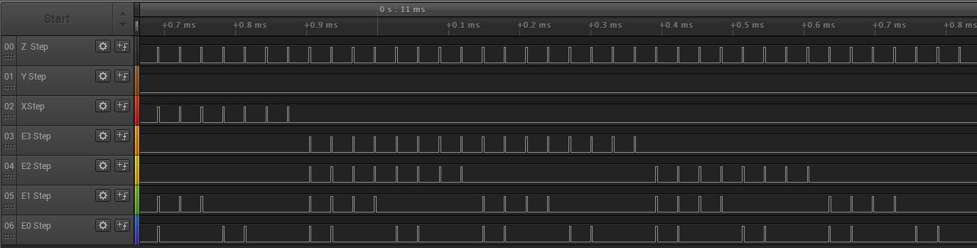
Hooking up the logic analyzer shows the clear test pattern.Each puls is a stepper motor step command.
![]()
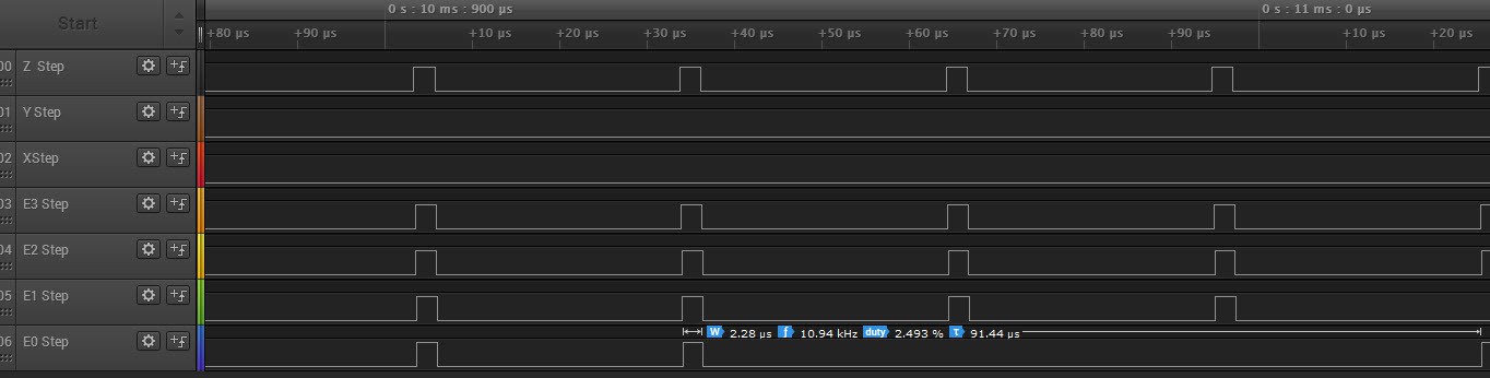
Zoomed in
![]()
Zooming even more in you clearly short pulses that are a bit higher than 2µS.
![]()
The code that generates the puls is below. I use one bit per motor to drive the simultaneously. Then a silly loop with a "nop" in it that generates a pulse with that is a bit higher than the required 2µS
void MotorCommand::StepMotorPulseDelay2Micros() {
    // Code blow should be about 2 µS on a 84 Mhz Arduino Due
    for (auto i = 0; i < 36; ++i) {
        asm("nop \n");
    }
}
void MotorCommand::SendMotorStepCommand(byte step_command) {
	// Make the signal high
	SendMotorStepHighCommand(step_command);
	StepMotorPulseDelay2Micros();

	// Make the signal low
	SendMotorStepLowCommand(step_command);
	StepMotorPulseDelay2Micros();
}

void MotorCommand::SendMotorStepHighCommand(byte step_command) {
    byte level = step_command;

    level = step_command & MOTOR_BIT_Z;
    if (level != 0) REG_PIOD_SODR = PIO_PD0;        // Z_AXIS_STEP set to high, bit 7

    level = step_command & MOTOR_BIT_Y;
    if (level != 0) REG_PIOB_SODR = PIO_PB26;        // Y_AXIS_STEP set to high, bit 6

    level = step_command & MOTOR_BIT_X;
    if (level != 0) REG_PIOC_SODR = PIO_PC3;        // X_AXIS_STEP set to high, bit 5

    level = step_command & MOTOR_BIT_E3;
    if (level != 0) REG_PIOC_SODR = PIO_PC7;        // E3_AXIS_STEP set to high; bit 4

    level = step_command & MOTOR_BIT_E2;
    if (level != 0) REG_PIOA_SODR = PIO_PA19;        // E2_AXIS_STEP set to high, bit 3

    level = step_command & MOTOR_BIT_E1;
    if (level != 0) REG_PIOC_SODR = PIO_PC19;        // E1_AXIS_STEP set to high, bit 2

    level = step_command & MOTOR_BIT_E0;
    if (level != 0) REG_PIOC_SODR = PIO_PC16;        // E0_AXIS_STEP set to high, bit 1
}

void MotorCommand::SendMotorStepLowCommand(byte step_command) {
    REG_PIOD_CODR = PIO_PD0;                        // Z_AXIS_STEP set to low
    REG_PIOB_CODR = PIO_PB26;                       // Y_AXIS_STEP set to Low
    REG_PIOC_CODR = PIO_PC3;                        // X_AXIS_STEP set to Low
    REG_PIOC_CODR = PIO_PC7;                        // E3_AXIS_STEP set to low
    REG_PIOA_CODR = PIO_PA19;                       // E2_AXIS_STEP set to low
    REG_PIOC_CODR = PIO_PC16;                       // E0_AXIS_STEP set to low
    REG_PIOC_CODR = PIO_PC19;                       // E1_AXIS_STEP set to low
    return;
}
The idea is to have pre-calculated motor bits ready in memory that can, be read at a fast rate and executed by a timer. The time above is at 32Khz, which means that a 200 Steps motor, at 32 microso-steps has about 5 revolutions per second.
This may seem fast but the Thor robot has geared steps with a 5:1 ration and then we have another gear X:1 slowing it even more. I image think about having to have only 16 or maybe even 1 micro step per motor.
Next step direction and enable control.
-
Motor control: The timer interrupt driver
05/16/2017 at 20:20 • 0 commentsThe code developed for Thor is intended to make the robot move like a ballet dancer. I am not controlling 1 or 2 motors but SEVEN at a time and they must all move like ballet dancers because we are moving real big masses that has inertia. Or worse, has maybe fluids.
In order to have perfect control over acceleration and deceleration we need a predictable timing that is independent of anything else I do to calculate the next steps or check for user input.
The whole purpose of the robot is to move! All else is secondary except for an emergency button. ON top of that primary focus is the mass it has to transport. That mass is more massive than a standard top of a 3D printer. The motor execution workflow must take that into account.
![]()
The code to generate a timer interrupt on an Arduino Due (used by the Ultratronics v1.0 motherboard) was harder to find. It is different than an Arduino Uno/Mega.
The code below is what drives the output you see at the logic analyzer at 32767 Hz.
#define timerFrequency 32767

// Black magic
void startTimer(Tc *tc, uint32_t channel, IRQn_Type irq, uint32_t frequency) {
	pmc_set_writeprotect(false);
	pmc_enable_periph_clk((uint32_t)irq);
	TC_Configure(tc, channel, TC_CMR_WAVE | TC_CMR_WAVSEL_UP_RC | TC_CMR_TCCLKS_TIMER_CLOCK4);
	uint32_t rc = VARIANT_MCK / 128 / frequency; //128 because we selected TIMER_CLOCK4 above
	TC_SetRA(tc, channel, rc / 2); //50% high, 50% low
	TC_SetRC(tc, channel, rc);
	TC_Start(tc, channel);
	tc->TC_CHANNEL[channel].TC_IER = TC_IER_CPCS;
	tc->TC_CHANNEL[channel].TC_IDR = ~TC_IER_CPCS;
	NVIC_EnableIRQ(irq);
}

// This function is called every 1/40 sec.
void TC3_Handler() {
	// You must do TC_GetStatus to "accept" interrupt
	// As parameters use the first two parameters used in startTimer (TC1, 0 in this case)
	TC_GetStatus(TC1, 0);

	motorProcessor->ExecuteStep();
}

void setup() {
	// Start timer. Parameters are:

	// TC1 : timer counter. Can be TC0, TC1 or TC2
	// 0   : channel. Can be 0, 1 or 2
	// TC3_IRQn: irq number. See table.
	// 40  : frequency (in Hz)
	// The interrupt service routine is TC3_Handler. See table.

	startTimer(TC1, 0, TC3_IRQn, timerFrequency);
}
I have not figured out yet how to proceed from here,. Many ideas.
It is easy to say that I want to move the 7 motors as a ballet dancers, if your driving engine is a huge PC with tons of memory and 4 Ghz CPU. The challenge is to contain it to have as much possibilities cramped into a small memory space.
That is what made me decide to start with Thor,. It challenges me to do stuff that everyone else claim that it cannot be done. :-)
I already have some ideas:
- Pre-calculated motor control data before the actual move.
- Movement patterns stored onto an sd CARD.
- Compressing the movement data.
- Secondary helper Arduino's used as co-processors.
- ...
-
Motor control: faster and faster
05/14/2017 at 20:48 • 0 commentsTesting for faster speed.
I am using a timer interval to trigger the motor motion.
By having a loop of "NOP" I managed to get a predictable step pulse of 2.24 - 2.32µS
void MotorExecutionBlock::StepDelay() {
	// Code blow should be about 2 µS on a 84 Mhz Arduino Due
	for (auto i = 0; i < 40; ++i) {
		asm("nop \n");
	}
}

void MotorExecutionBlock::SendMotorStepCommand(byte step_command) {
        REG_PIOC_SODR = PIO_PC3;		    // X_AXIS_STEP set to high
        REG_PIOB_SODR = PIO_PB26;		    // Y_AXIS_STEP set to high
        REG_PIOD_SODR = PIO_PD0;		    // Z_AXIS_STEP set to high
        REG_PIOC_SODR = PIO_PC16;		    // E0_AXIS_STEP set to high
        REG_PIOC_SODR = PIO_PC19;		    // E1_AXIS_STEP set to high
        REG_PIOA_SODR = PIO_PA19;		    // E2_AXIS_STEP set to high
        REG_PIOC_SODR = PIO_PC7;		    // E3_AXIS_STEP set to high

	// Delay 2 micro seconds
	StepDelay();

	REG_PIOC_CODR = PIO_PC3;		    // X_AXIS_STEP set to Low
	REG_PIOB_CODR = PIO_PB26;		    // Y_AXIS_STEP set to Low
	REG_PIOD_CODR = PIO_PD0;		    // Z_AXIS_STEP set to low
	REG_PIOC_CODR = PIO_PC16;		    // E0_AXIS_STEP set to low
	REG_PIOC_CODR = PIO_PC19;		    // E1_AXIS_STEP set to low
	REG_PIOA_CODR = PIO_PA19;		    // E2_AXIS_STEP set to low
	REG_PIOC_CODR = PIO_PC7;		    // E3_AXIS_STEP set to low
}
Which gives these fine tuned motor control![]()
I now speed up the clock pulses (driven by an interrupt) and get a speed of 32 Khz
![]()
The bonus is that I have at this speed only used 7.6% of the CPU processing cycles,, I still have 92.4% of available time to do something useful with the processor.
Controlling 7 stepper motors at 32 Khz and have 92% CPU processing power to spare. Think we are on to something. :-)
I also have been running at this speed for 5 minutes and no smoke to see.
-
A solution: More efficient stepper motor control
05/13/2017 at 22:42 • 1 commentUsing this method we lose about 5µS per stepper motor we want to control.
digitalWrite(X_AXIS_STEP, level);
As sampled by the logic analyzer below.![]()
Each stepper motor gets a pulse 2µS later than the previous one accumulating a delay.
This puts our robot in a wait state that could have been used for productively instead.
But we found a way to control the Due processor directly.
The documentation was a bit confusing and information is hard to find but this is the key.REG_PIOC_SODR = PIO_PC3; // X_AXIS_STEP set to high digitalWrite(E0_AXIS_STEP, 0); // Delay 2 micro seconds REG_PIOC_CODR = PIO_PC3; // X_AXIS_STEP set to LowWe use direct port mapping and write the bit directly to the PIO.
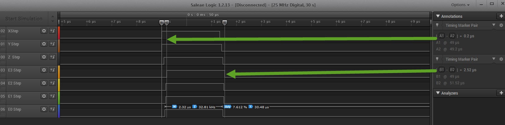
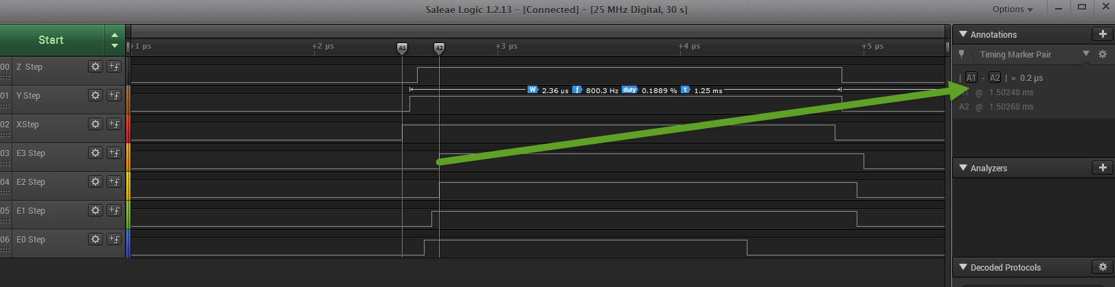
And for 7 stepper motors we end up with something below. We lose 0.2 µS instead of
![]()
The code that was executes is seen below.
However it does not explain why we have differences in ending of the pulses. The smaller pulse is only 1.76 µS which may be a bit too short.void MotorExecutionBlock::SendMotorStepCommand(byte step_command) { REG_PIOC_SODR = PIO_PC3; // X_AXIS_STEP set to high REG_PIOB_SODR = PIO_PB26; // Y_AXIS_STEP set to high REG_PIOD_SODR = PIO_PD0; // Z_AXIS_STEP set to high REG_PIOC_SODR = PIO_PC16; // E0_AXIS_STEP set to high REG_PIOC_SODR = PIO_PC19; // E1_AXIS_STEP set to high REG_PIOA_SODR = PIO_PA19; // E2_AXIS_STEP set to high REG_PIOC_SODR = PIO_PC7; // E3_AXIS_STEP set to high // Delay 2 micro seconds digitalWrite(E0_AXIS_STEP, 0); REG_PIOC_CODR = PIO_PC3; // X_AXIS_STEP set to Low REG_PIOB_CODR = PIO_PB26; // Y_AXIS_STEP set to Low REG_PIOD_CODR = PIO_PD0; // Z_AXIS_STEP set to low REG_PIOC_CODR = PIO_PC16; // E0_AXIS_STEP set to low REG_PIOC_CODR = PIO_PC19; // E1_AXIS_STEP set to low REG_PIOA_CODR = PIO_PA19; // E2_AXIS_STEP set to low REG_PIOC_CODR = PIO_PC7; // E3_AXIS_STEP set to low }We can optimize even more because some bits are mapped to the same PIO (e.g. 4 bits to PIOC), gaining 4x40=160 ns.
The only question is: Does the power supply and motherboard handle 7 simultaneous steps easily?
-
Stepper motor driving core. Determining the code efficiency
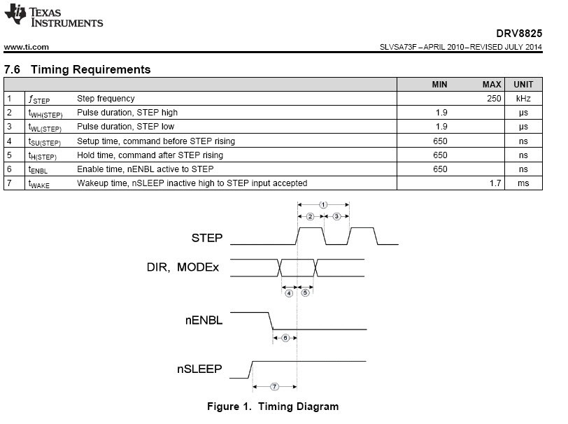
05/12/2017 at 22:50 • 0 commentsFor the Thor project I have choose the Ultratronics board v1.0 in combination with DRV8825 Stepper Motor Controller.
According to the specification the stepper pulse must be 1.9 µS high and then 1.9 µS low again to drive one step.
![]()
The code I try to use to drive these 7 stepper motors
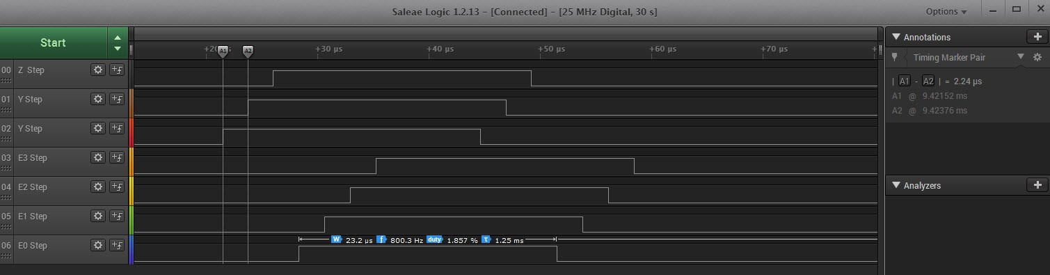
void MotorExecutionBlock::SendMotorDirectionCommand(byte direction_command) {
	byte level = (direction_command >> 6) & 0x01;
	digitalWrite(X_AXIS_DIRECTION, level);

	level = (direction_command >> 5) & 0x01;
	digitalWrite(Y_AXIS_DIRECTION, level);

	level = (direction_command >> 4) & 0x01;
	digitalWrite(Z_AXIS_DIRECTION, level);

	level = (direction_command >> 3) & 0x01;
	digitalWrite(E0_AXIS_DIRECTION, level);

	level = (direction_command >> 2) & 0x01;
	digitalWrite(E1_AXIS_DIRECTION, level);

	level = (direction_command >> 1) & 0x01;
	digitalWrite(E2_AXIS_DIRECTION, level);

	level = (direction_command >> 0) & 0x01;
	digitalWrite(E3_AXIS_DIRECTION, level);
}
According to the logic analyzer every code line turns out to take 2.24 µS.7 times 2.24 = 15.7 µS
byte level = (direction_command >> 6) & 0x01; digitalWrite(X_AXIS_DIRECTION, level);![]()
After I have sent all 7 step commands, I intended to wait the desired 2µS delay, but in the above logic analyzer sampling it clearly is takes 23.2 µS
void MotorExecutionBlock::SetMotorStep(byte step_command) {
	// Bit 1 means set the step
	step_command = 0x7F; //
	SendMotorStepCommand(step_command);
	// wait 2 micro seconds (example below is 1000 micros seconds but for now...
	MicroDelay(2);

	SendMotorStepCommand(0);
	MicroDelay(2);
}
The Micro delay code is shown. For some reason this code takes 23.2µS
static void MicroDelay(unsigned long delayTime)
    auto started_waiting_at = micros();
    do {
	auto currentTime = micros();
	auto passedTime = (currentTime - started_waiting_at);
	if (passedTime > delayTime) {
         	break;
        }
    } while (true);
}
Any wait code means that we lose CPU cycles that could have been used for calculations the next phase.
I am thinking about using a simple dummy DigitalWrite command as a way to delay 2µS instead of the micros() method. The step pulse width does not have to be accurate as long as it is > 1.9 µS.
The speed of the stepper motors next pulse are determined by an timer interrupt. And independent of this micro delay.
The total time stuck to this one 7 stepper motor pulse is 36.92 µS when we could have had 2 µS.
Time to improve this code!
To be continued....
-
Stepper motor driving core. First measurements
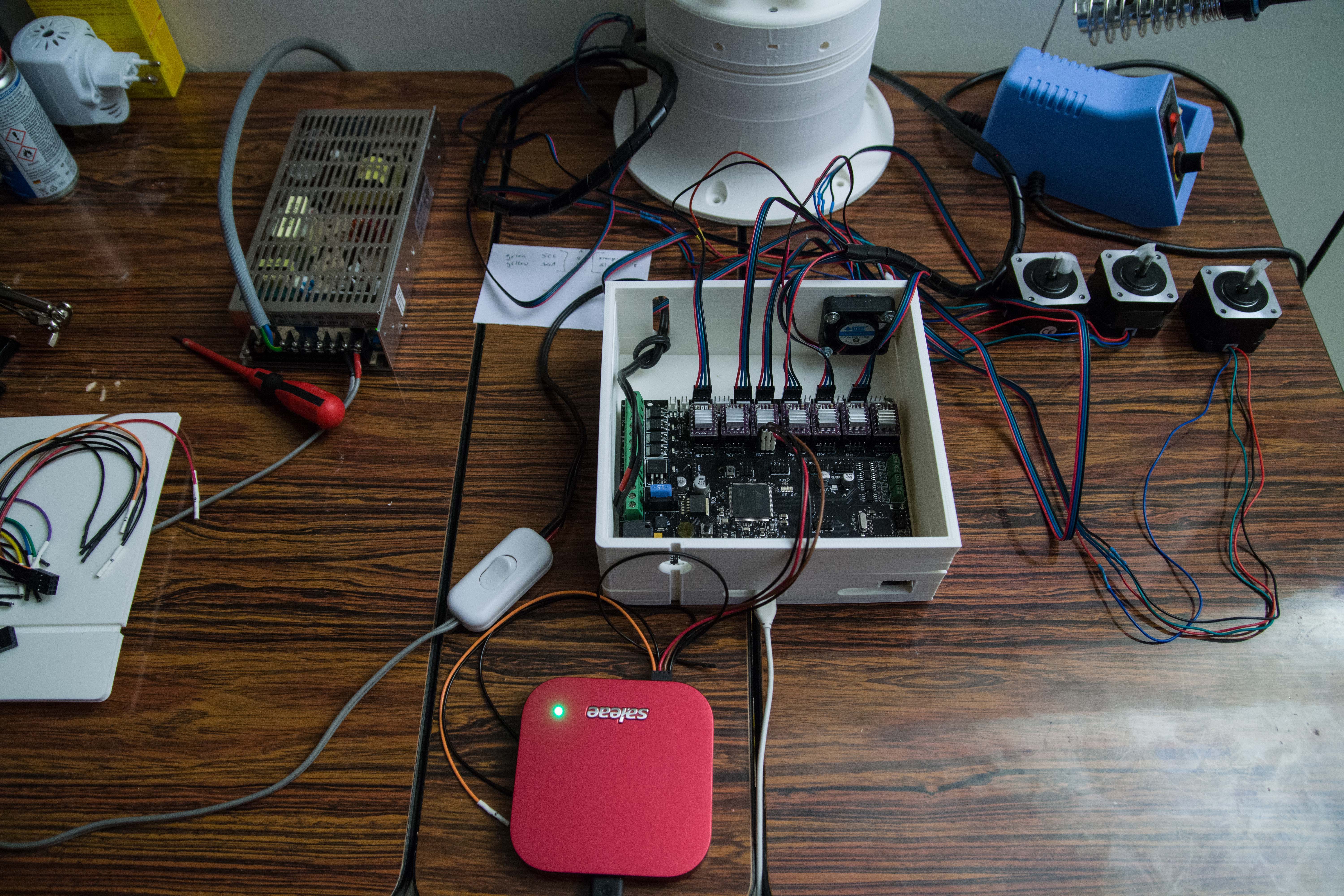
05/12/2017 at 01:36 • 0 commentsYou don't need an expensive logic analyzer to be able test the setup. The $10 logic analyzer I originally had would have helped a lot in developing the core code.
I initially started by using the debug LED to test the development, but a logic analyzer speed things up. :-) The ability to test the code without need of motors. It makes you test the code for extreme situations without risk of damaging anything.
For the Thor robot I use the Ultratronics Board v1.0. The board comes with sockets for the DRV8825 stepper motor drivers. If you destroy one, you can easily replace one.
The nice thing about this board is also that they also provided break-out pins where I can hook my logic analyzer to.
![]()
So I connected the logic analyzer to one of the DRV8825 drivers. The Saleae can also measure the analog signals for each digital input.
![]()
The DRV8825 needs 3 controls.
- The direction you want to take motor to (rotate left or right)
- The step pulse (that must be minimal 2x1.9 µS wide)
- The enable to actually activate this motor.
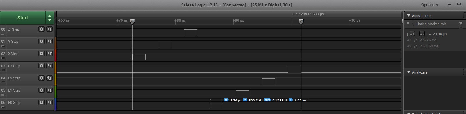
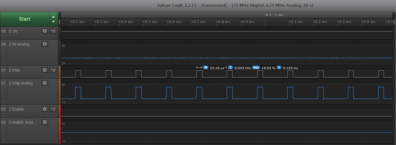
It can only process no more than 250.000 steps/Sec. Example above is testing at 8 Khz.
The pulse width in the above example is 26.16 µS, I was trying for 2 µS programatically. The smaller that puls is, the more free time I have for additional calculations.
I also want to point out that this is interrupt driven. This motor will operate at that speed no matter how much time I use in my main loop. The key to all this, is to fill its processing execution buffer with enough data to keep it busy.
The whole purpose of this interrupt driven technology I develop is to have smooth movements that will take into account acceleration and deceleration.
![]()
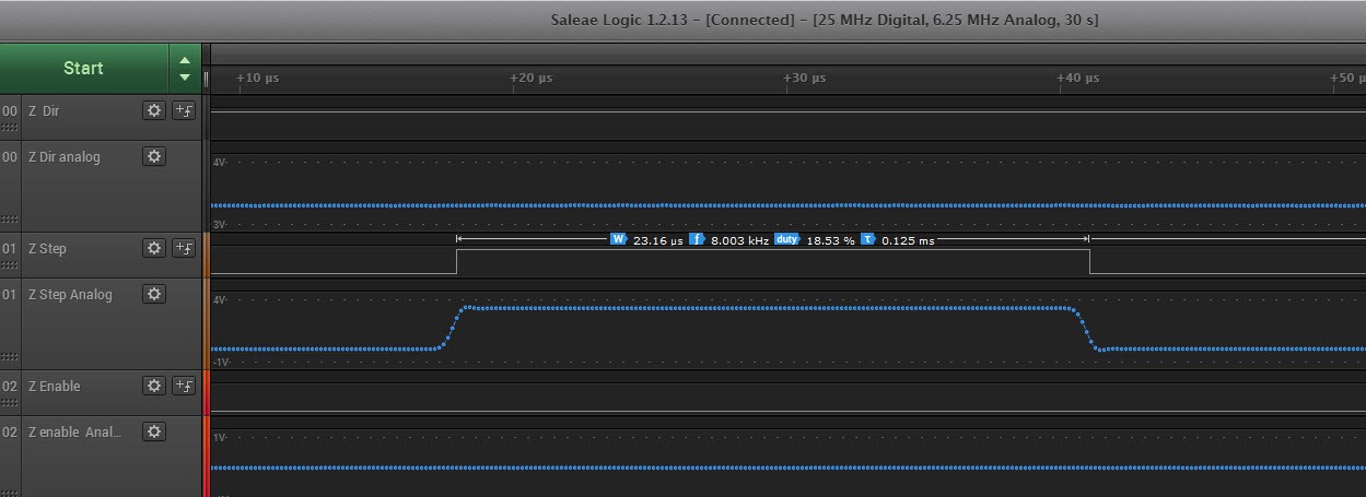
Close up view of the analogue signal actually produced by the Arduino Due. Nice clear signal.
Next tests will be digital only and see how the code behaves when I operate 7 stepper motors at the same time. There is a reason why I need a 16 channel logic analyzer ;-)
Building the Thor robot
Building a 6-axis robot based on the Thor robot. When size DOES matter!