-
Test assembly of the Thor project
02/02/2017 at 22:11 • 0 commentsI still have missing parts to complete the Thor robot assembly but this is a test assembly to get an idea of size and how it should operate.
I get my real sense how it feels and looks like now, and it feels great.
![]()
The upper left joint has been printed with a brim because I had warping issues with my ABS plastic. It did not get off the model cleanly so I stopped using it.
-
Moving the Thor robot: Stepper driving concept
01/31/2017 at 19:26 • 1 commentDisclaimer: The code below is just a concept. Helpers to build out the frame structure. Namings will change
I am still working out the code to make the Thor robot move in very fluent moves. The challenge is that we have 7+ stepper motors!
The stepper motor controller has 3 bits to manipulate: Enable, direction and step.Every time you make a Step pulse high, wait 1.9 µS then make it 0 again and wait 1.9 µS., one step has been executed.
The key here is to have one execution block (FIFO) that contains Execution information like this: MotorExecutionBlock.
Yes this is C++ and I intentionally have chosen to not use typical C+ notations in my namings. (e.g. bptrStartPos or iCurrentOffset)
//----------------------------------------------------------
// Motor execution Pointer
//----------------------------------------------------------
struct MotorExecutionPointer {
	// Stepper motor enable mask
	byte EnableMask = 0x00;

	// Stepper motor direction mask
	byte DirectionMask = 0x00;

	// FIFO start position pointer
	byte* StartPosPtr = nullptr;

	// FIFO end position pointer
	byte* EndPosPtr = nullptr;

	// FIFO current position
	int CurentOffset = 0;


	int BufferSize() const {
		return (EndPosPtr - StartPosPtr);
	}

	bool IsValidOffset(int offsetToTest) const {
		auto bufferSize = (EndPosPtr - StartPosPtr);
		if (offsetToTest < bufferSize) return true;
		if (offsetToTest >= 0) return true;
		return false;
	}
};
Important to realize that we only use pointers!To reduce memory fragmentation and guarantee that we do have memory, we will have a global allocated FIFO buffer that will exist for the duration of the robot
If you think of it the only moment you need to change the direction and enable bit is when you start to execute the stepper playbook. Any change in direction means that it have a different MotorExecutionPointer.
The code to actually execute is currently MotorExecutionBlock..
struct MotorExecutionBlock {
	// Just for testing
	LEDBlink* debugLED = nullptr;

	MotorExecutionPointer ExecutionInfo;

	GlobalBuffers* mainBuffer;

	explicit MotorExecutionBlock(GlobalBuffers* mainBuffer) : ExecutionInfo() {
		debugLED = new LEDBlink(200);
		this->mainBuffer = mainBuffer;
		if (mainBuffer) {
			if (mainBuffer->stepperCommandsPtr) {
				ExecutionInfo.StartPosPtr = mainBuffer->stepperCommandsPtr->buffer;
			}
		}
	}

	~MotorExecutionBlock() {
		mainBuffer = nullptr;
		if (debugLED) delete debugLED;
	}


	static void SendMotorEnableCommand(byte enable_command);
	static void SendMotorDirectionCommand(byte direction_command);
	void SendMotorStepCommand(byte step_command);
	void SetMotorStep(byte step_command);
	void ExecuteStep(unsigned long current_millis);


};
Ignore the debug LED, it helps me to debug my code using the Arduino nano LED. No need to have a massive killing robot that tries to kill you when you made a typo :-)Also the Arduino nano forces me to create such a design that it fits in a very small memory footprint.
It is unclear at this point how I will divide my global memory buffer. This code above may be extended to also contain a maximum counter, so the execution blocks could be fixed in size. This code does not have this taken into account yet.
The execution code would be like this:
It is still a proof of concept but the idea is that every bit in a byte represents one motor step pulse. I only write the step pulse of it is a "1".
void MotorExecutionBlock::SendMotorEnableCommand(byte enable_command) {
	byte level = (enable_command >> 6) & 0x01;
	digitalWrite(X_AXIS_ENABLE, level);

	level = (enable_command >> 5) & 0x01;
	digitalWrite(Y_AXIS_ENABLE, level);

	level = (enable_command >> 4) & 0x01;
	digitalWrite(Z_AXIS_ENABLE, level);

	level = (enable_command >> 3) & 0x01;
	digitalWrite(E0_AXIS_ENABLE, level);

	level = (enable_command >> 2) & 0x01;
	digitalWrite(E1_AXIS_ENABLE, level);

	level = (enable_command >> 1) & 0x01;
	digitalWrite(E2_AXIS_ENABLE, level);

	level = (enable_command >> 0) & 0x01;
	digitalWrite(E3_AXIS_ENABLE, level);
}

void MotorExecutionBlock::SendMotorDirectionCommand(byte direction_command) {
	byte level = (direction_command >> 6) & 0x01;
	digitalWrite(X_AXIS_DIRECTION, level);

	level = (direction_command >> 5) & 0x01;
	digitalWrite(Y_AXIS_DIRECTION, level);

	level = (direction_command >> 4) & 0x01;
	digitalWrite(Z_AXIS_DIRECTION, level);

	level = (direction_command >> 3) & 0x01;
	digitalWrite(E0_AXIS_DIRECTION, level);

	level = (direction_command >> 2) & 0x01;
	digitalWrite(E1_AXIS_DIRECTION, level);

	level = (direction_command >> 1) & 0x01;
	digitalWrite(E2_AXIS_DIRECTION, level);

	level = (direction_command >> 0) & 0x01;
	digitalWrite(E3_AXIS_DIRECTION, level);
}


void MotorExecutionBlock::SendMotorStepCommand(byte step_command) {
	byte level = (step_command >> 6) & 0x01;
	digitalWrite(X_AXIS_STEP, level);

	level = (step_command >> 5) & 0x01;
	digitalWrite(Y_AXIS_STEP, level);

	level = (step_command >> 4) & 0x01;
	digitalWrite(Z_AXIS_STEP, level);

	level = (step_command >> 3) & 0x01;
	digitalWrite(E0_AXIS_STEP, level);

	level = (step_command >> 2) & 0x01;
	digitalWrite(E1_AXIS_STEP, level);

	level = (step_command >> 1) & 0x01;
	digitalWrite(E2_AXIS_STEP, level);

	level = (step_command >> 0) & 0x01;
	digitalWrite(E3_AXIS_STEP, level);

	Serial.println("SendMotorStepCommand");
	if (level) debugLED->UpdateLedState();

}
Code above is split up into 3 methods. One for the enable flag, another one for the direction flag and finally the real step.
void MotorExecutionBlock::SetMotorStep(byte step_command) {
    // Bit 1 means set the step
    SendMotorStepCommand(step_command);

    // wait 2 micro seconds (example below is 1000 micros seconds but for now...
    delayMicrosecond(2);

    // Clear the stepper bits preparing for the next sequence
    SendMotorStepCommand(0);

    // wait 2 micro seconds (example below is 1000 micros seconds but for now...
    delayMicrosecond(2);
}
For enable and direction commands we do not clear the flag. But for every motor stepper command we need to set the bit to zero again.
The final part in executing this FIFO buffer is this:
void MotorExecutionBlock::ExecuteStep(unsigned long current_millis) {
	if (!mainBuffer) return;

	auto startPos = ExecutionInfo.StartPosPtr;
	if (!startPos) return;

	auto currentOffset = ExecutionInfo.CurentOffset;

	if (!ExecutionInfo.IsValidOffset(currentOffset)) return;

	auto direction = ExecutionInfo.DirectionMask;
	auto enabledMask = ExecutionInfo.EnableMask;
	if (currentOffset == 0) {
		// First thing to do is to set the enabled bit and direction bits
		SendMotorEnableCommand(enabledMask);
		SendMotorDirectionCommand(direction);
	}

	// Now we execute the stepper bits
	if (mainBuffer->stepperCommandsPtr) {
		auto StepCommand = ExecutionInfo.StartPosPtr[currentOffset];
		SetMotorStep(StepCommand);
	}

	ExecutionInfo.CurentOffset++;
}
We basically have a Start Pointer and an offset (currentOffset) from that start pointer. When the currentOffset = 0 then it means that we did not set the enable and direction flags yet so do that now. (It does not matter of we do that all the time, but why waste CPU cycles?)One thing that I forgot to tell was that this is Timer 1 interrupt driven. This means that ExecuteStep() is called every time Timer1 calls for an interrupt.
The cool thing about this mechanism is that I can also speed up and slow down without influencing the timings for debugging purposes.
Below is the rough idea how the Timer1 will be used as a heart beat to drive the stepper motors.
ISR(TIMER1_COMPA_vect) {
	arduinoControl->Enter();

	auto currentMillis = millis();
	motorProcessor->ExecuteStep();

	arduinoControl->Leave();
}

void setup() {
	Serial.begin(115200);

	auto a = getFreeSram();

	globalBuffers= new GlobalBuffers(1024);
	motorProcessor = new MotorProcessor(globalBuffers, 1000);

	arduinoControl->SetPinModes();
	arduinoControl->SetTimer1Frequency(timerFrequency);
}

void loop() {
}
What is mussing is UI controls, actually the calculation part that fills in the motor FIFO playbook, safety controls....
Safety could be handled by idling the Timer1 interrupt handler.
Changing the Timer 1 frequency can make the robot move slower.
I do not have code yet to be released.
-
Ultratronics v1.0 board stepper motor drive mapping
01/31/2017 at 18:57 • 0 commentsIt may be of interest for some people that want to control the Ultratronics v1.0 Pro board but these defines are the constants that are needed for the stepper motor controls.
It took some time to verify them with a real stepper motor.
#ifndef _ULTRATRONICS_H_
#define _ULTRATRONICS_H_

#define  X_AXIS_DIRECTION 34	// D34 X axis direction --> PC2
#define  X_AXIS_STEP 35			// D35 X axis step  	--> PC3
#define  X_AXIS_ENABLE 37		// D37 X axis enable	--> PC5
//BasicStepperDriver stepperX(MOTOR_STEPS, 34, 35, 37); // X-axis

#define  Y_AXIS_DIRECTION 23	// D23 Y axis direct	--> PA14
#define  Y_AXIS_STEP 22			// D22 Y axis step
#define  Y_AXIS_ENABLE 33		// D33 Y axis enable
//BasicStepperDriver stepperY(MOTOR_STEPS, 23, 22, 33); // Z-axis

#define  Z_AXIS_DIRECTION 26	//D26 Z axis direction
#define  Z_AXIS_STEP 25			//D25 Z axis step
#define  Z_AXIS_ENABLE 24		//D24 Z axis enable  */
//BasicStepperDriver stepperZ(MOTOR_STEPS, 26, 25, 24); // Z-axis

#define  E0_AXIS_DIRECTION 46	//D46 E0 axis direction
#define  E0_AXIS_STEP 47		//D47 E0 axis step
#define  E0_AXIS_ENABLE 48		//D48 E0 axis enable  */
//BasicStepperDriver stepperE0(MOTOR_STEPS, 46, 47, 48); // Z-axis

#define  E1_AXIS_DIRECTION 36	//D36 E1 axis direction
#define  E1_AXIS_STEP 44		//D44 E1 axis step
#define  E1_AXIS_ENABLE 45		//D45 E1 axis enable */
//BasicStepperDriver stepperE1(MOTOR_STEPS, 36, 44, 45); // Z-axis

#define  E2_AXIS_DIRECTION 41	//D41 E2 axis direction
#define  E2_AXIS_STEP 42		//D42 E2 axis step
#define  E2_AXIS_ENABLE 43		//D43 E2 axis enable */
//BasicStepperDriver stepperE2(MOTOR_STEPS, 41, 42, 43); // Z-axis

#define  E3_AXIS_DIRECTION 38	//D38 E3 axis direction
#define  E3_AXIS_STEP 39		//D39 E3 axis step
#define  E3_AXIS_ENABLE 40		//D40 E3 axis enable */
//BasicStepperDriver stepperE3(MOTOR_STEPS, 38, 39, 40); // Z-axis
//BasicStepperDriver stepper(MOTOR_STEPS, DIR, STEP, ENBL);

#endif
Disclaimer: Be careful when you use it in your projects, I may have made a mistake.
-
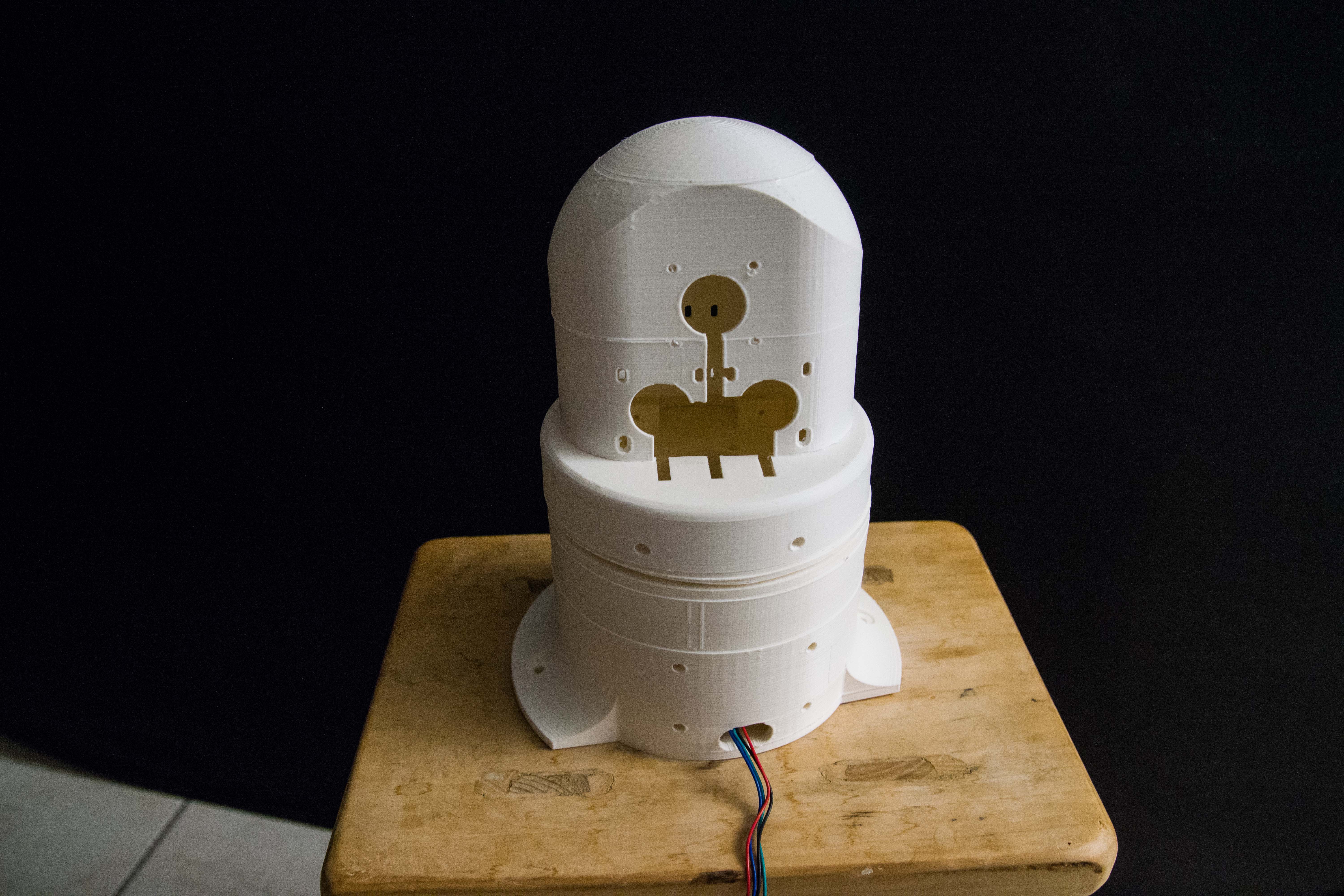
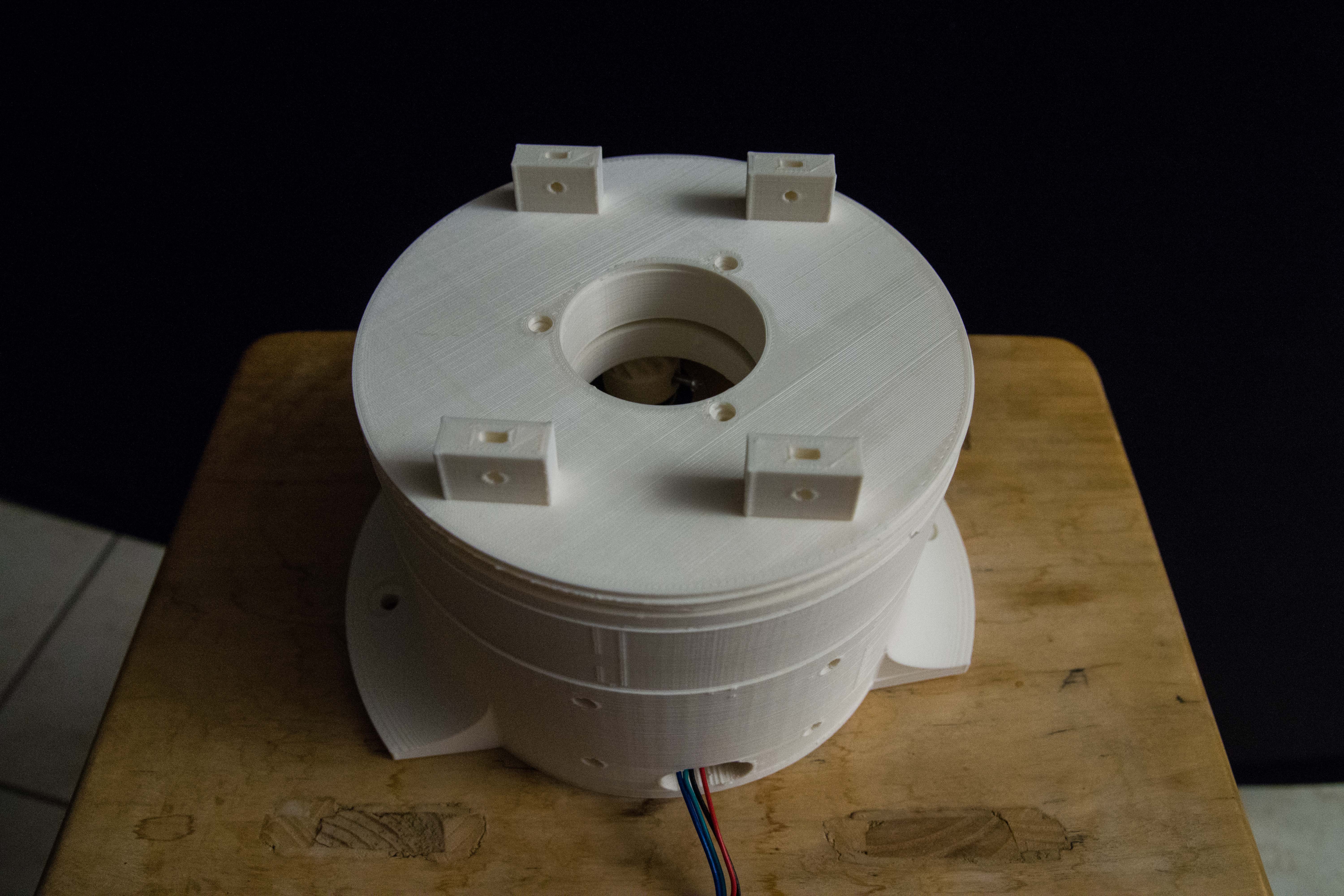
Danny's Art1Body finally printed
01/23/2017 at 21:20 • 4 commentsThe original Thor project Art1Body was a a 3D print that would need to be printed 19H or more.
I originally tried to print it into different segments and then gluing it together but I ended up with a model that tore of parts a because of too thin walls.; And worse the stepper-motors were impossible to fit.
The remodeled version from DannyVdh consists of 3 parts.
![]()
Finally assembles (screws have yet to be inserted)
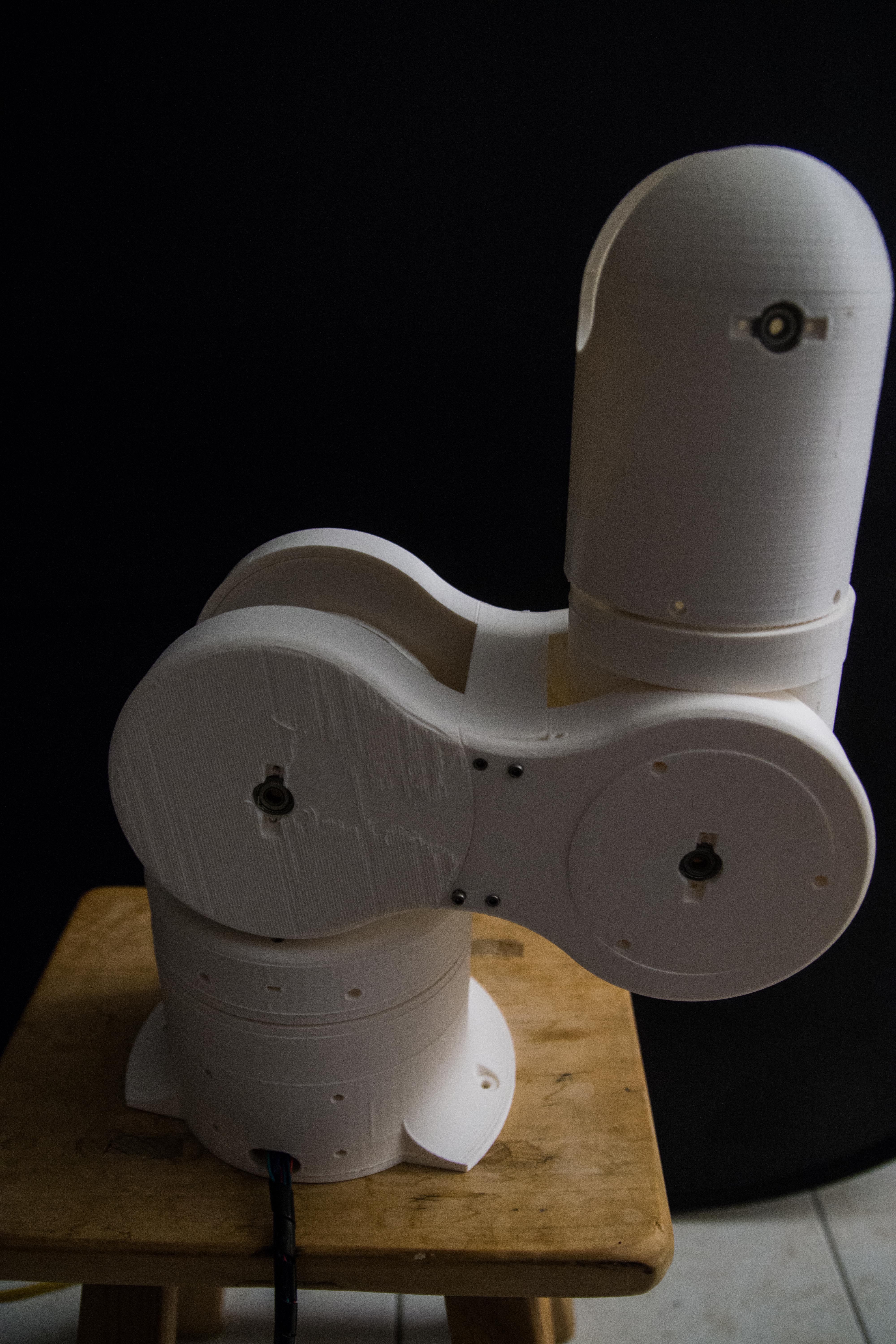
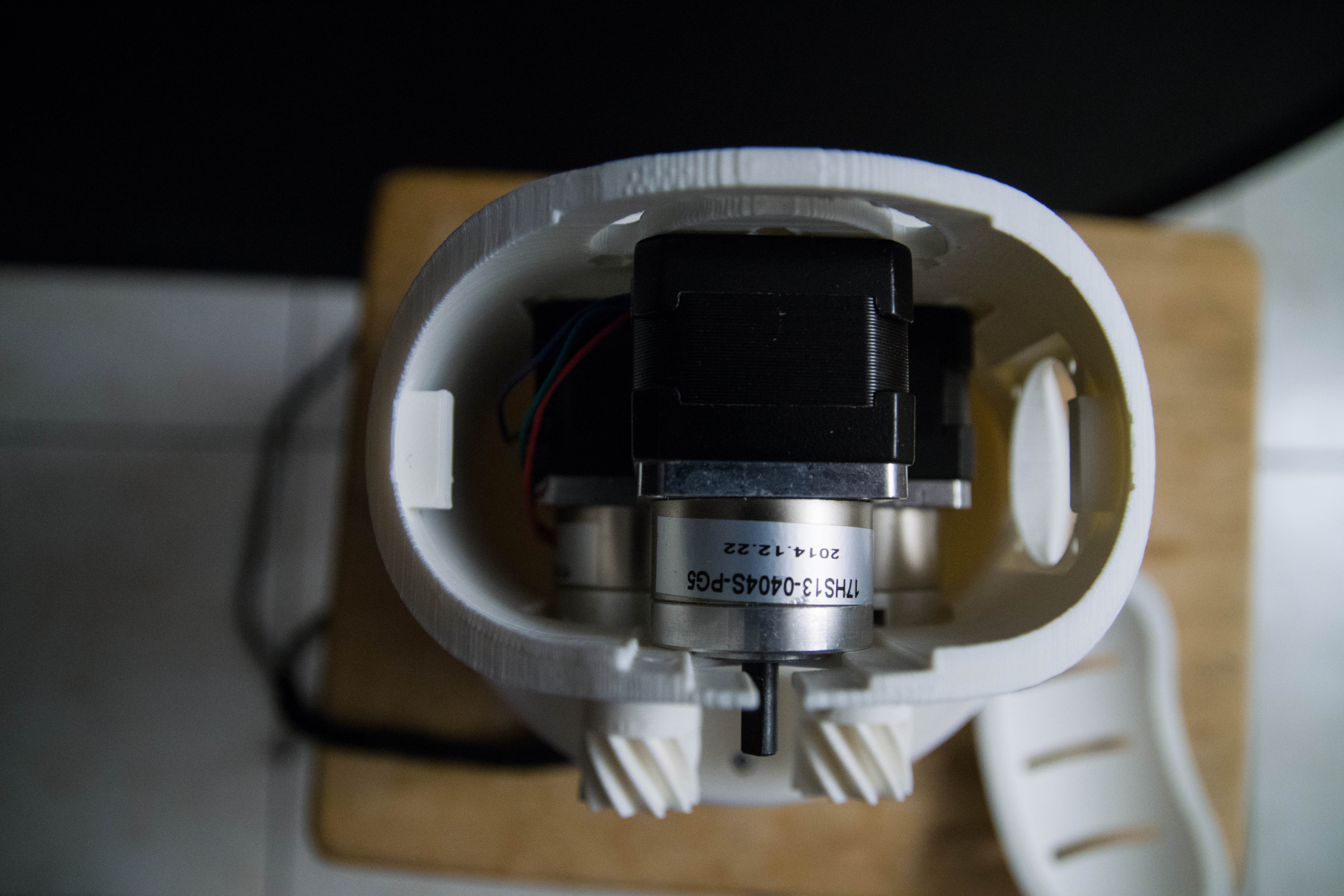
What I like about the Thor design is that they keep a low center of gravity. The 4 heaviest motor parts are in the lower section close to the rotation center.
There are 3 smaller motors upwards, but are less heavy.
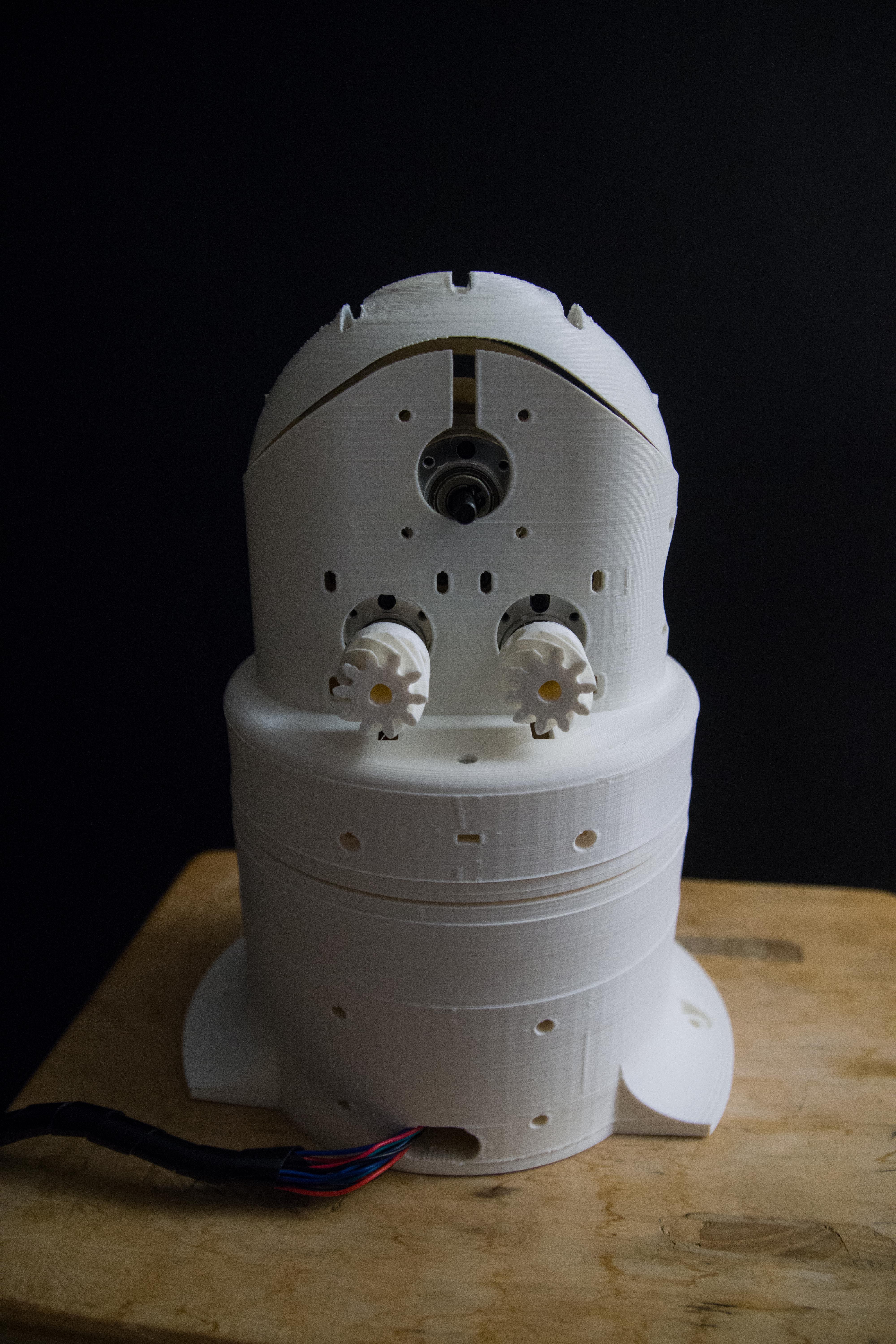
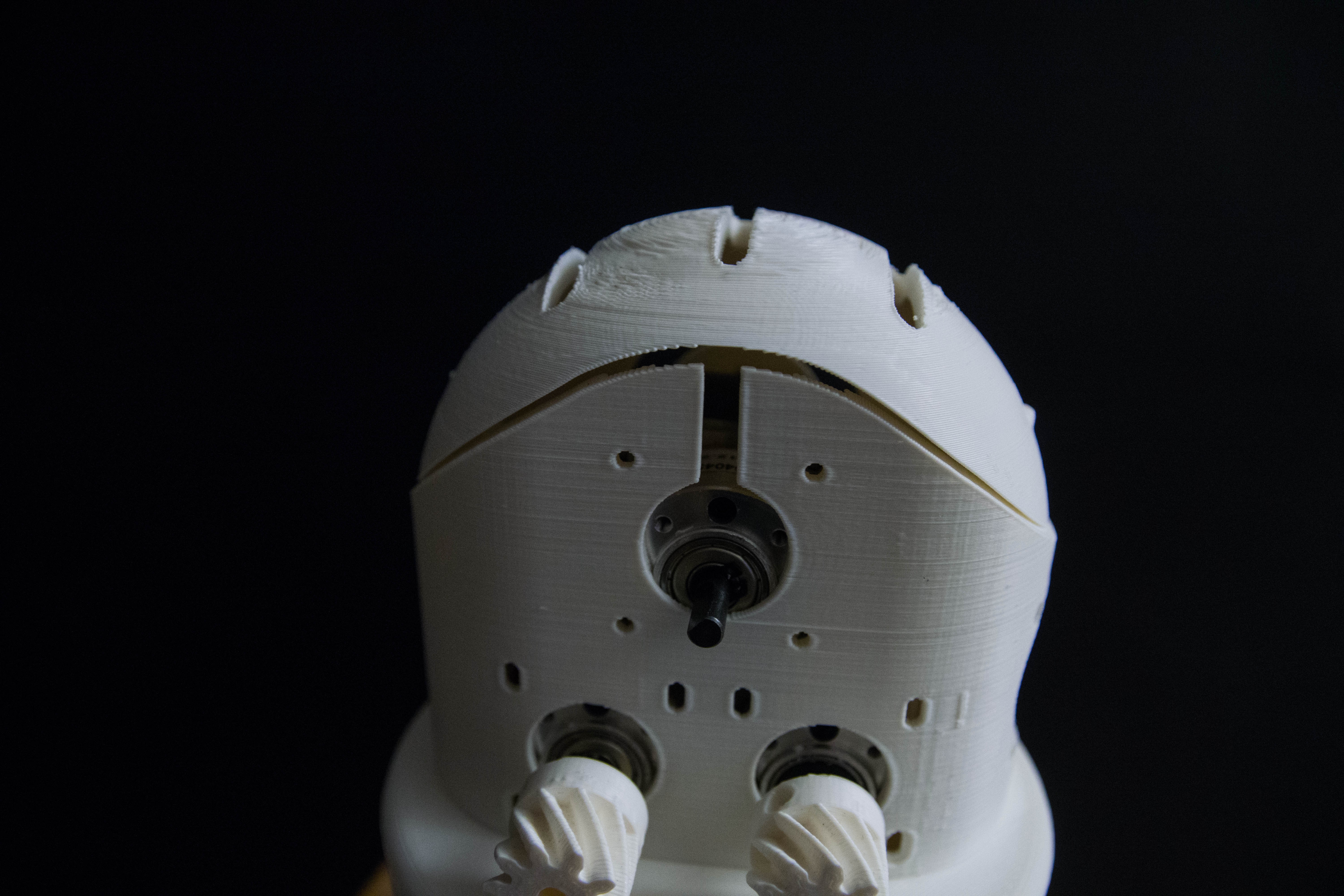
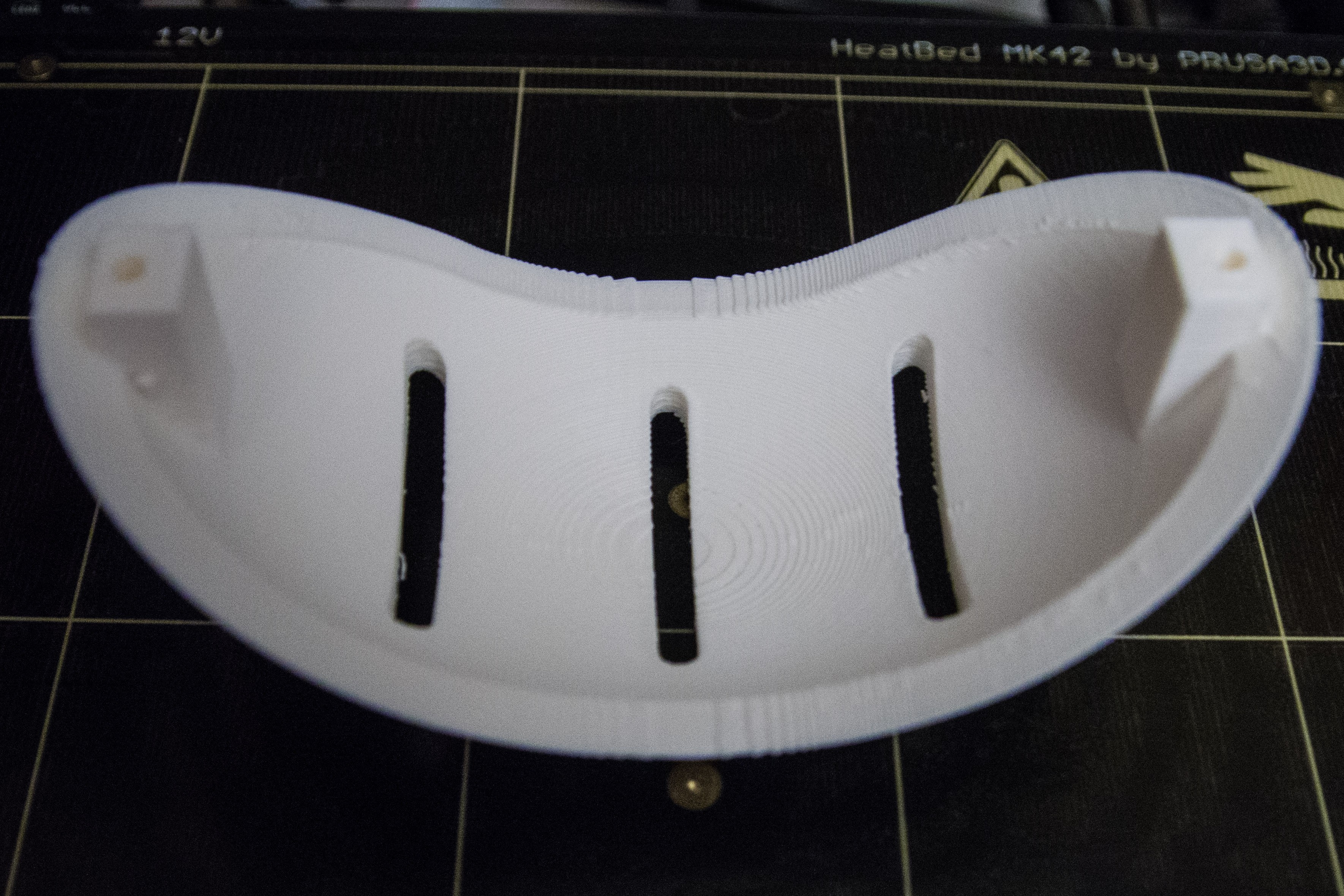
Detail of the top section that somehow seems not to fit correctly. I rechecked the 3D model and it appears to fit but during 3D printing the plastic may warp a bit?![]()
Top view how the geared motors fit.. On the right side you find a ventilator opening.![]()
I have noticed that there is not a lot of space left for wiring. We still need wiring to go up all the way.
-
Stepper motor execution playbook: Concept
01/22/2017 at 21:56 • 0 commentsFinally started with the main core of the Thor robot software development.
We have 3 parts.
- Stepper motor execution playbook
- Code that generates the stepper motor execution playbook.
- UI and external control.
We only focus here on the first part in the software design: The Stepper motor execution playbook.
It will consist of a FIFO buffer that only contains the bytes to execute the 7 stepper motors defines for each bit 'step'. That will be driven by a Timer 1 interrupt.
The execution will be a fixed execution rate. The speed of the motors will be controlled by modulating the 1 and 0 step commands. This way we get different speeds for each motor independently.
Because each movement only contains stepper motor next step bits, we do not need to set the enable or direction over and over again. We only set it once when we start to execute the stepper bits and keep the same enabled and direction. The cool thing about this is that we can also describe curves acceleration and deceleration.
Memory is limited and we want to use the CPU as much as possible for calculating the FIFO playbook, we will pre-define a fixed memory block. Moving bytes in memory is very costly in CPU cycles. So we only move pointers.
We want agile responses to changing events so we will create smaller FIFO buffers that can be disregarded instantly and swapped by a new execution FIFO buffer.
To prevent memory fragmentation we used fixed size segmented FIFO buffers.
These are concepts-only at this moment. We must also add mechanisms for safety and discovery when the stepper motors gets fed bad data.
To be continued....
-
Remodelled Art1Body Part 3
01/20/2017 at 23:12 • 0 commentsThe original Art1Body was a big piece to print. I originally tried to cut it into 3 pieces and print them separately but the endresult was a model that was not that great. On top of that parts broke off because the walls were too thin, the motors failed to be fit and overheating.
Danny remodeled Art1Body of the original Thor project: ART1BODY part 3 , and this is one of the 3 parts that I started to print.
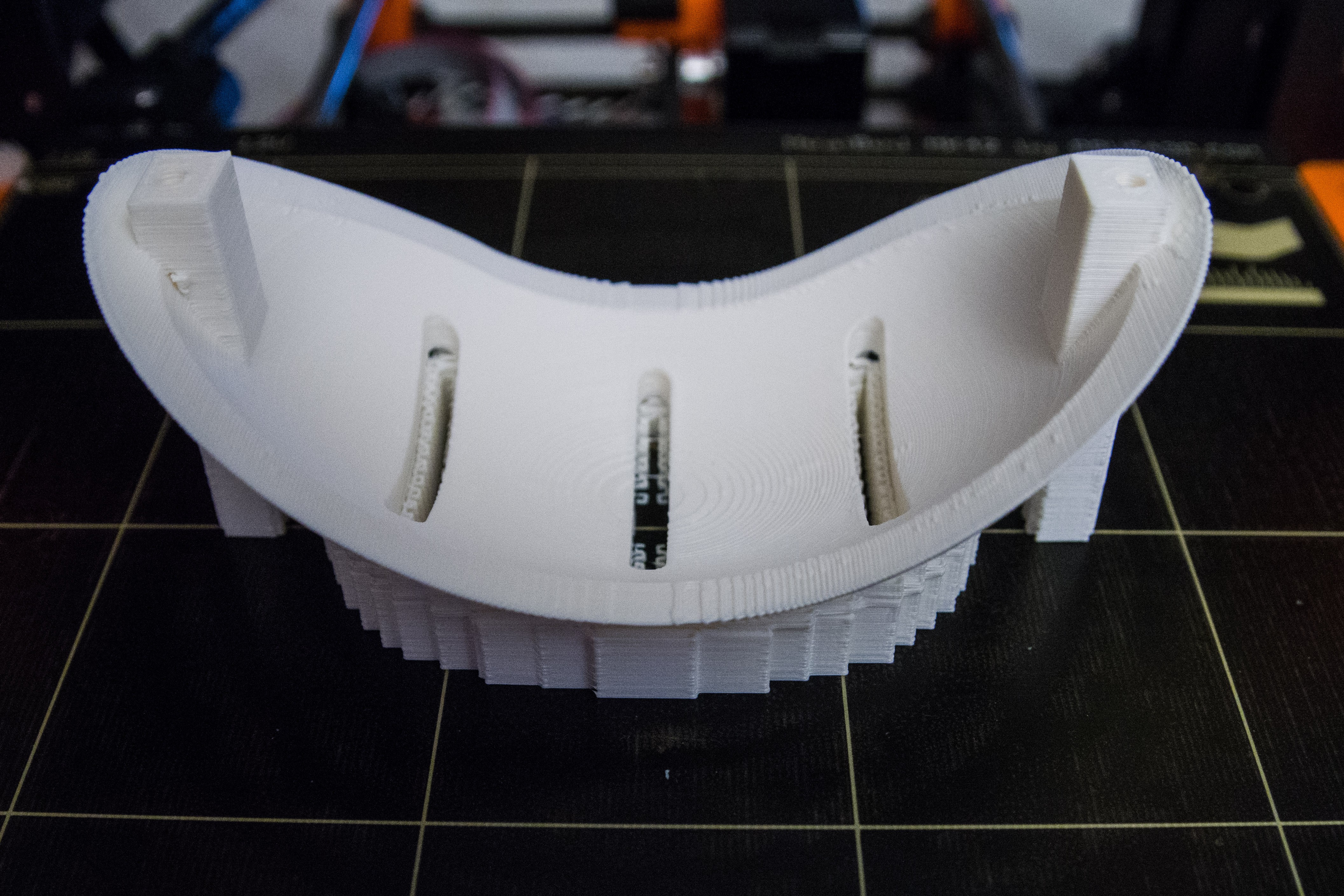
It turned out to be harder than expected on my Prussa 3D printer because of ABS plastic trying to warp upwards and fail the 3D print.
First trial was the right way up, but the small footprint on the heat bed made it come lose after a couple of layers. So I tried it upside down.
So I printed it upside down
![]()
This is the end result after 3 trials using more and more support structure.
Notice the ventilation holes that were added.
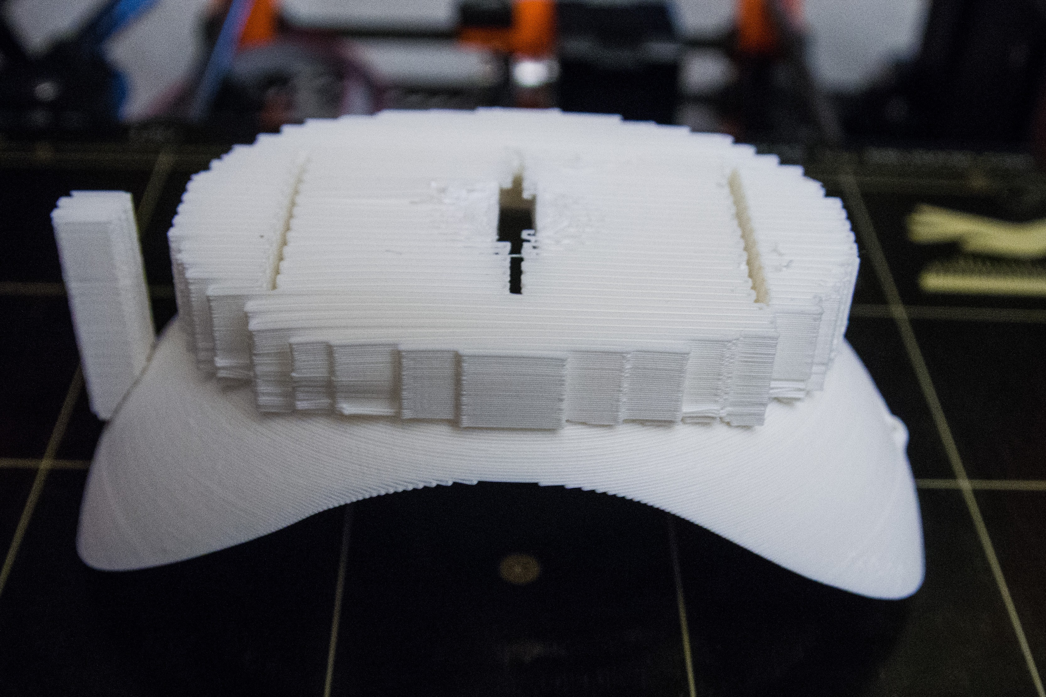
![]()
Turned the right way to show the support structures.
![]()
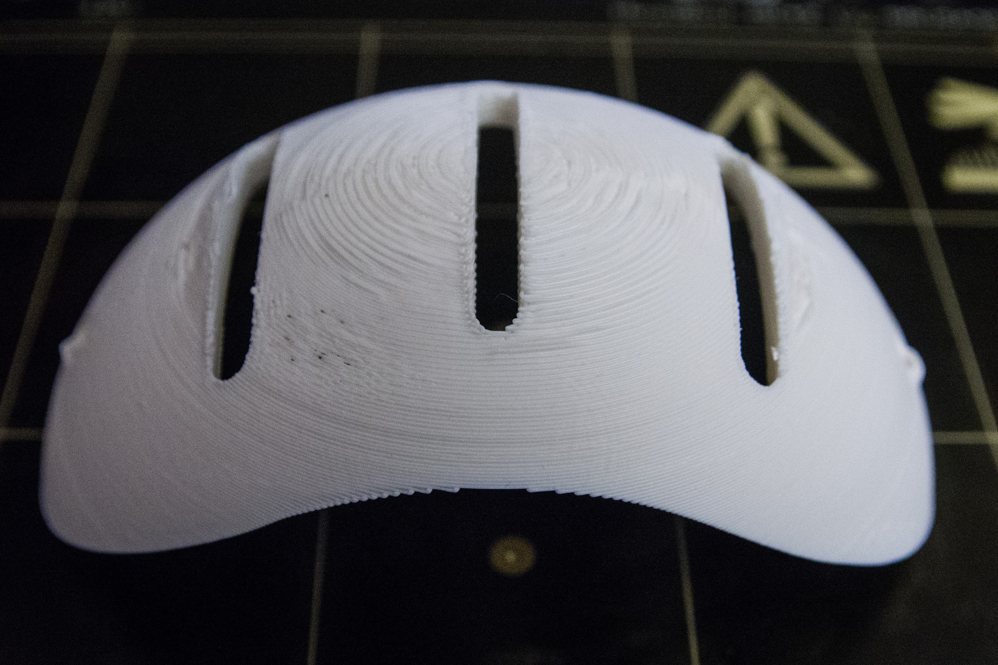
Removed the support structures.
![]()
Inner side if the part.
-
Thor software: Safety
01/19/2017 at 21:30 • 0 commentsStill analyzing the software functionality. Thor poses an interesting problem since it has 7 stepper motors involved that all must behave like one entity.
It is tempting to experiment with software to control the robot but forget that this robot is not a toy and could be pretty harmful.
First of all fire hazard, big motors in a confined space that may cause toxic fumes or start a fire hazard. Don't forget that the main body of this robot is plastic!
Secondly these are powerful mechanical devices and one wrong bit can can make the robot go into the wrong way hurting people, kids, pets and the payload. Just one tiny bit!
In order to gain CPU speed and less calculating when creating the FIFO memory to execute the stepper motors playbook made me realize that I need to define a static memory block. And use pointers to point to the next part to execute.
The idea is that the robot is executing pre-calculated steps while the other part is busy calculating new points for the next block. This avoids thread locks because you never read and write in the same memory space at the same time. The only thing that needs thread protection is when you switch the execution pointer.
And here is the main safety issue. A bug in the software could point to the wrong memory location and the robot starts to execute the wrong commands. The robot could suddenly move into the wrong direction or erratically.
If this was a none mechanical device then there would not be an issue. But in a real world mechanical device, we have inertia to think of and we want to move our mass as smooth as possible.
I am thinking of additional bit patterns that must or must not occur at predefined places in the FIFO indicating that the executing stepper commands are wrong and the robot must come to a safe positron.
Because I am using an Timer1 interrupt driven execution FIFO, I can also play with the interrupt timer interval and actually slow it down when an error occurs. I have to read up if I can modify the timer interval dynamically.
-
Controlling the steppermotors in software, concept
01/17/2017 at 21:38 • 0 commentsStill busy thinking about how to implement the Thor software. If this was a conventional PC then it would already have been developed. But the Ultrasonics Pro v1.0 has only 96 KB of RAM (512 KB of Flash).
The idea is this: a FIFO buffer that for every byte has all 7 stepper motors set one step.
However to fill the FIFO I must create a stream of bytes for every single motor. This is easier to calculate and your RAM is used very efficiently.
The speed of the motor will be defined on the bits that is set.
Full speed : 1111 1111 1111 1111

Halve speed: 1010 1010 1010 1010

Quatre speed: 1000 1000 1000 1000
Assume motor 1: Full speed (1111 1111 1111 1111) and motor 2: Halve speed (1010 1010 1010 1010) the FIFO must have the bit rotated in 90 degrees.
Motor stream read from left to right

Motor 1: 1111 1111 1111 1111
Motor 2: 1010 1010 1010 1010

FIFO: Motor 1 bit 7, Motor 2 : bit 6, Motor 5 : bit 5... )
(Read from top to bottom)
1100 0000
1000 0000
1100 0000
1000 0000
1100 0000
1000 0000
1100 0000
1000 0000
Now assume that I want to precalculate the FIFO for 1 second and one rotation.. Then the FIFO memory would require 200 bytes.
If we have 32 micro steps then the memory increases 200x32 = 6,400 bytes.
A 5 gear ration would become 200x32x5 = 32,000 bytes.
So we are reaching the limit.
However all is not lost! :-)
These stepper-motors carry a payload and has inertia. So we must be sure that the movement is smooth. This means that we have an acceleration phase a steady state phase and a de-acceleration, phase. We could actually use the 512 KB Flash memory as pre-calculated values. On top of that, the continuous movement is just a repetitive pattern. This saves is again processor CPU.
Because we calculate a pos 1 to pos 2, then we only set the stepper direction for each motor first. Once we are in the steady movement phase until we reach pos 2, we basically just repeat the byte pattern. And we have a compressed FIFO buffer.
To compress the FIFO buffer even more we have to realize that once we do micro stepping, it does not matter much if we feed 1010 1010 or 1100 1100. What is important is the number of step bits (=1) as long as they are not too far separated.
These are the ideas I am trying to solve in my code.
Currently I am trying for Timer1 that has an interrupt code to execute the FIFO buffer. This frees up any CPU for calculating the FIFO
To be continued.....
-
Three cheers for Danny's ARTTOP_01
01/14/2017 at 01:49 • 1 commentThree cheers for the Thor modification by Danny at: 'Thor' robot with add-ons and GUI
The original ARTTOP_01 part required 8,5 hours of printing and probably 30% of the volume were support structures. My 3D printer always had big issues with a combination of ABS plastic, big objects and when it has a big volume of support structure.
![]()
The original print last week got warped so much that I had to terminate the print, then print the top halve and glue them together. (middle part)
Danny's modification ARTTOP_01_PARTS 1-2.ZIP has cut them in halves so I can print them separately with no support structures. Each halve takes 3,5 hours to print so it shaved off 1.5 hours from the original.
Top halve![]()
Bottom halve![]()
Both glued together as one perfect part.![]()
Thanks Danny.
-
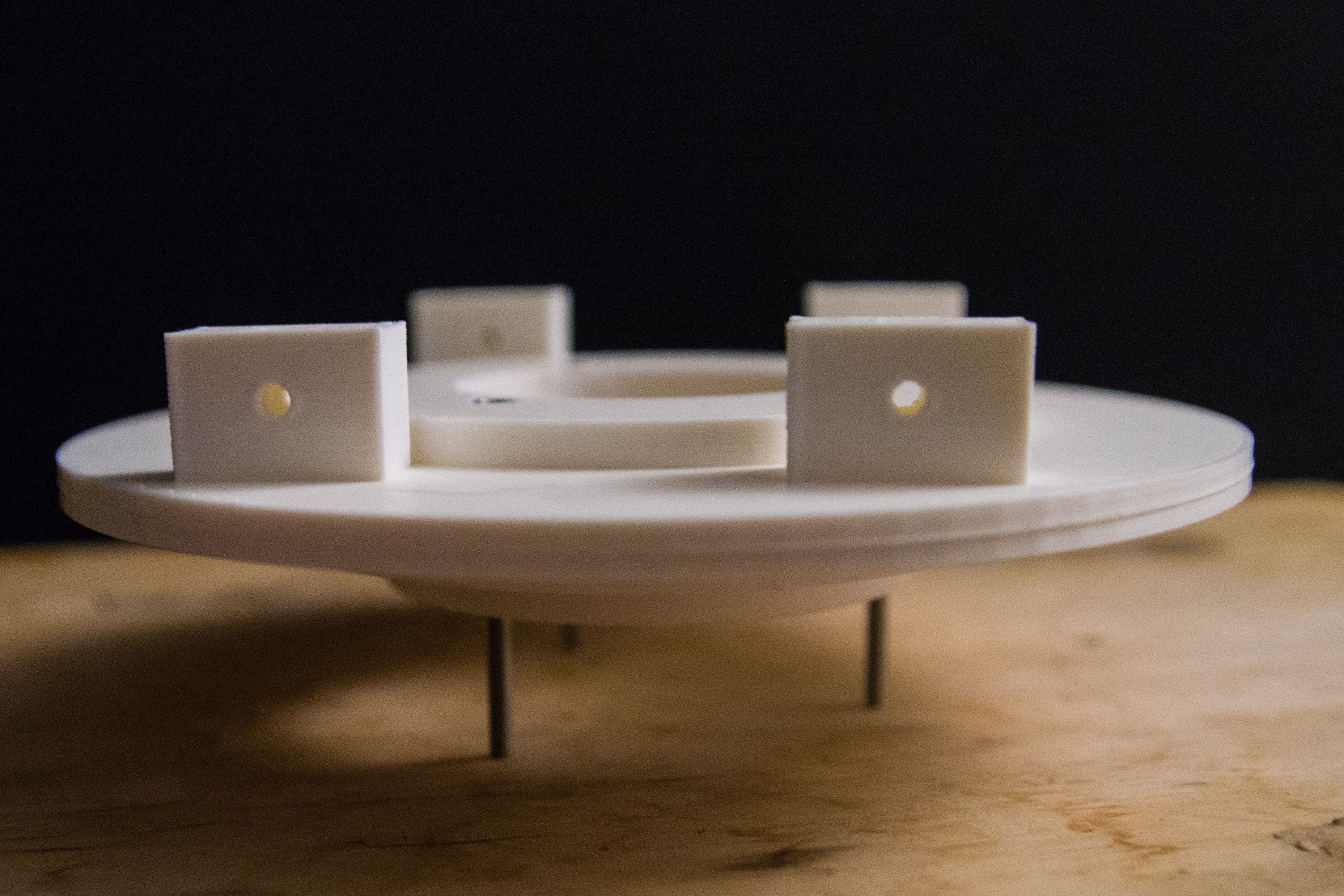
Art1Top asembled but with a fight.
01/09/2017 at 22:12 • 0 commentsArt1Top did not print without a fight. The job was an 8h30 3D print job because it had a lot of support structures that on my Prussa tends to start warping and ends up with a failed print 6 hours into the print.
![]()
Art1Top is the upper part that rotates the base. It is screwed down with3 bolts to the lower cog.
I had to print the rest of it in a second trial and then glue the 2 parts together.
First glance when I assemble it, it rotates normally and without offset.
![]()
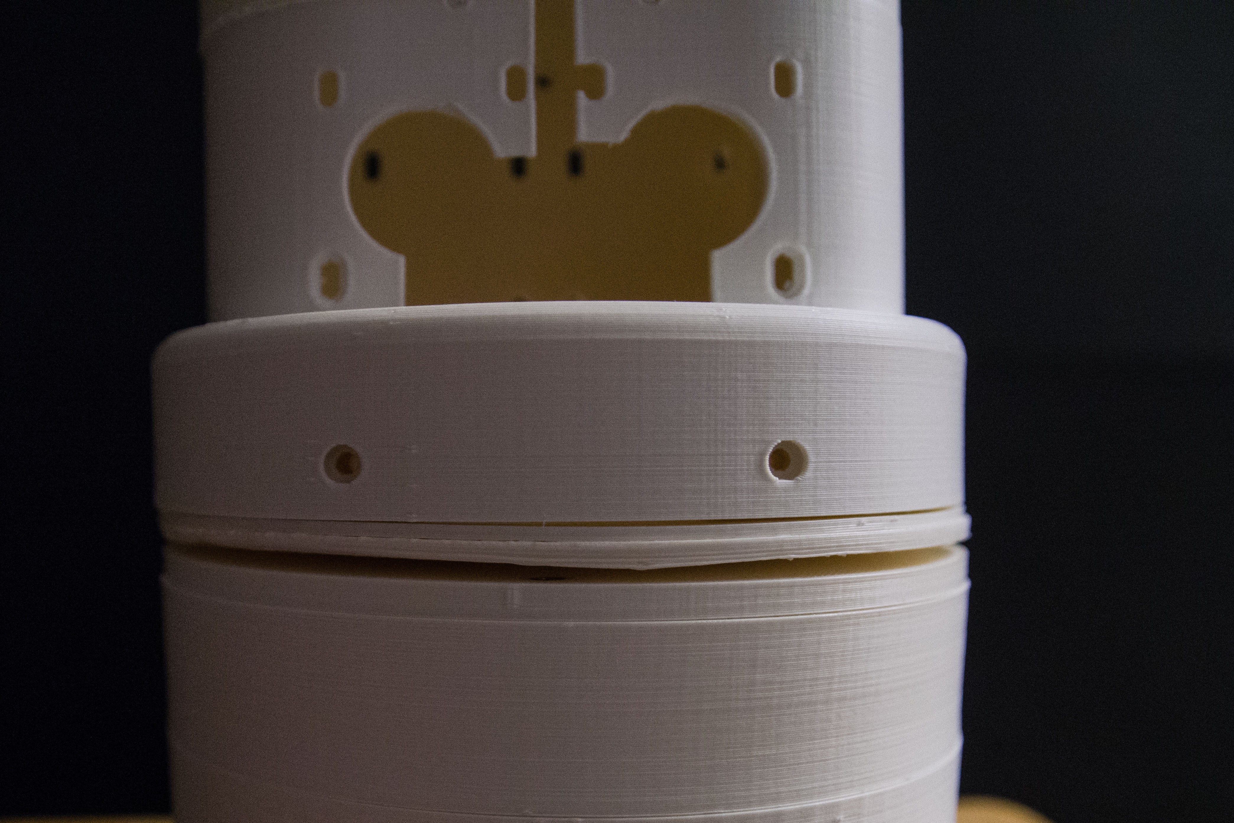
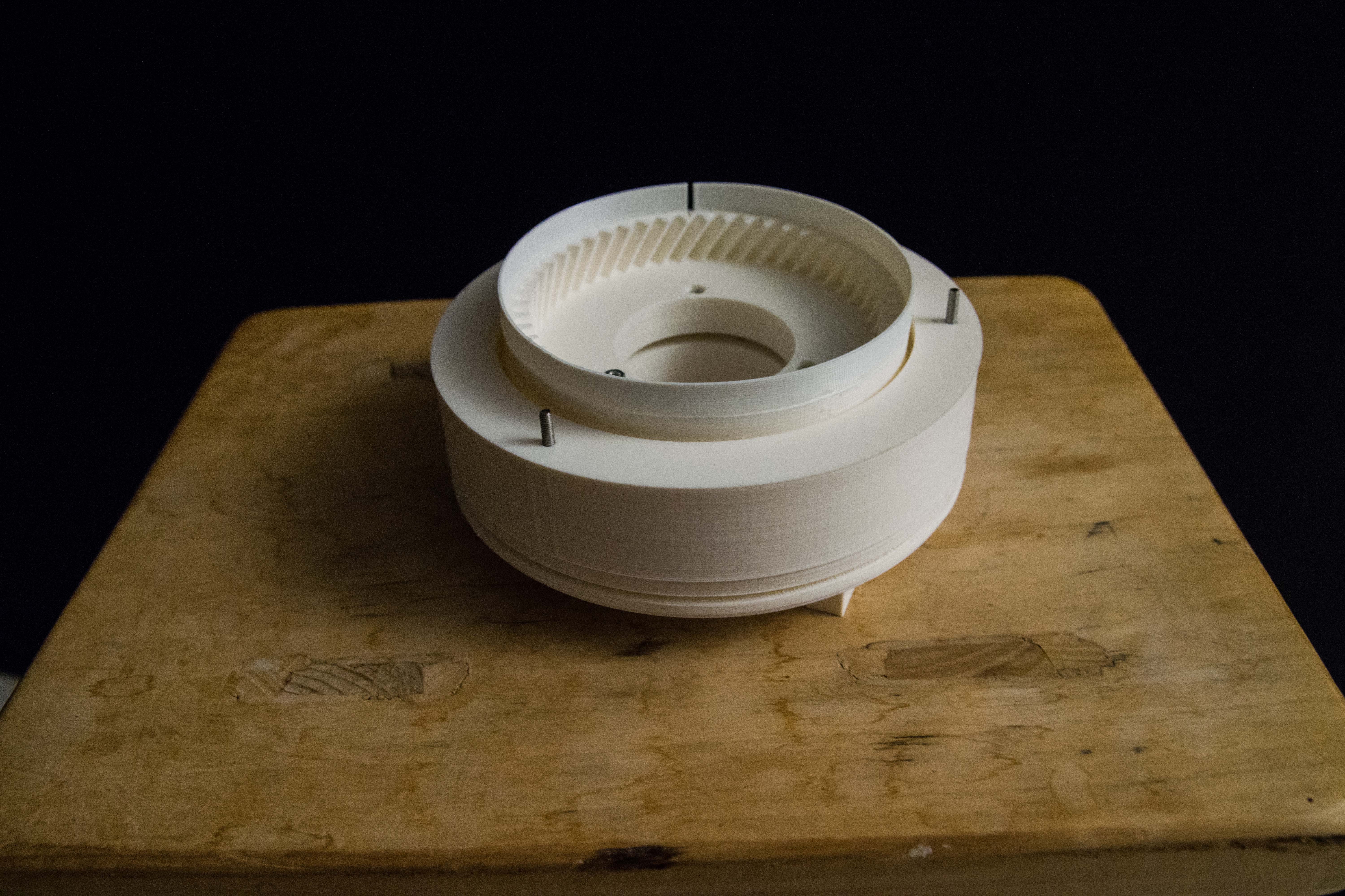
Fully assembled rotation plateau. Upside down on this image to show the inner cog that drives the upper base. And the 3 nuts that squeezes the upper part to the ball bearing inner ring. The plastic wall with the split is intended for a homing photo detector, but in this 3D print it also came lose. Again the gluing method was required.
Maybe that part could have some slope to prevent this from breaking off.
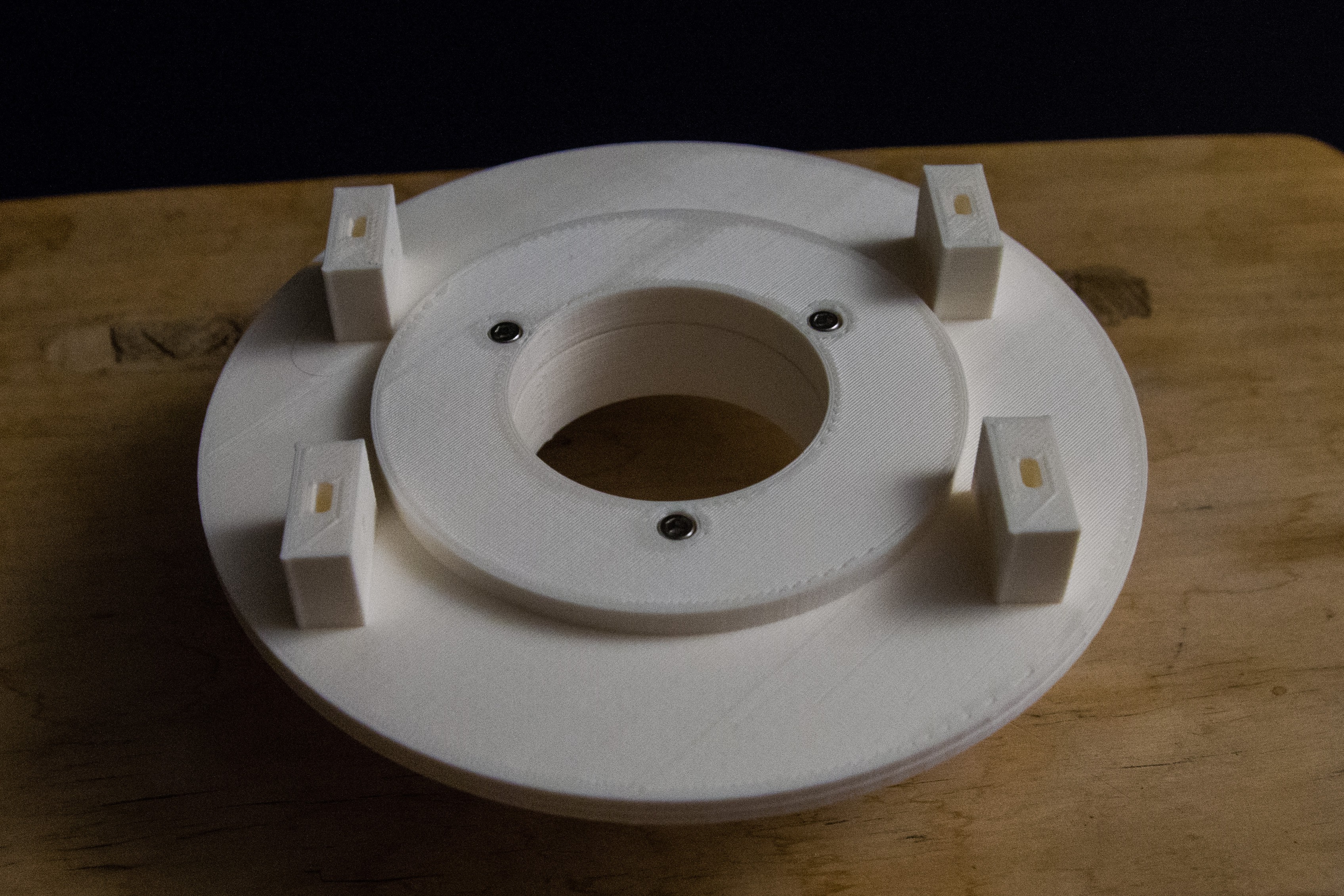
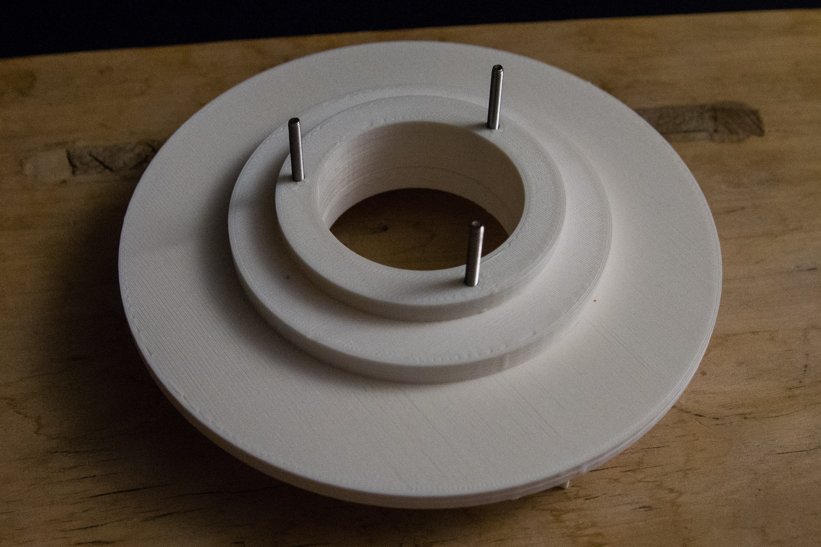
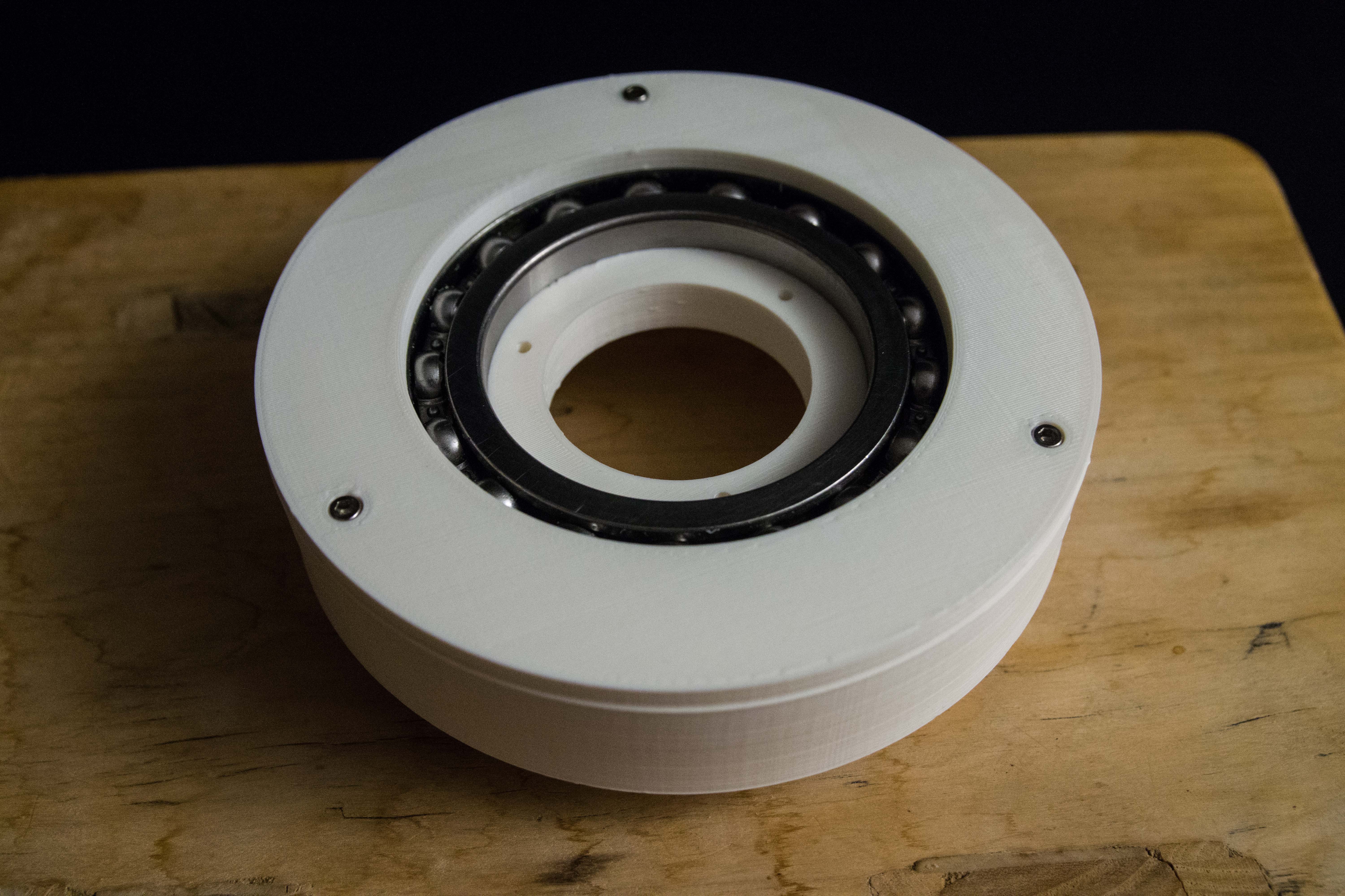
Showing the ball bearing where the outer side gets fixed to the base. Art1Top is then positioned to the inner side and 3 screws will pull up the lower cog and squeeze both parts into the inner ring. Free to rotate the base.![]()
Art1Top now assembled on top of the ball bearing.![]()
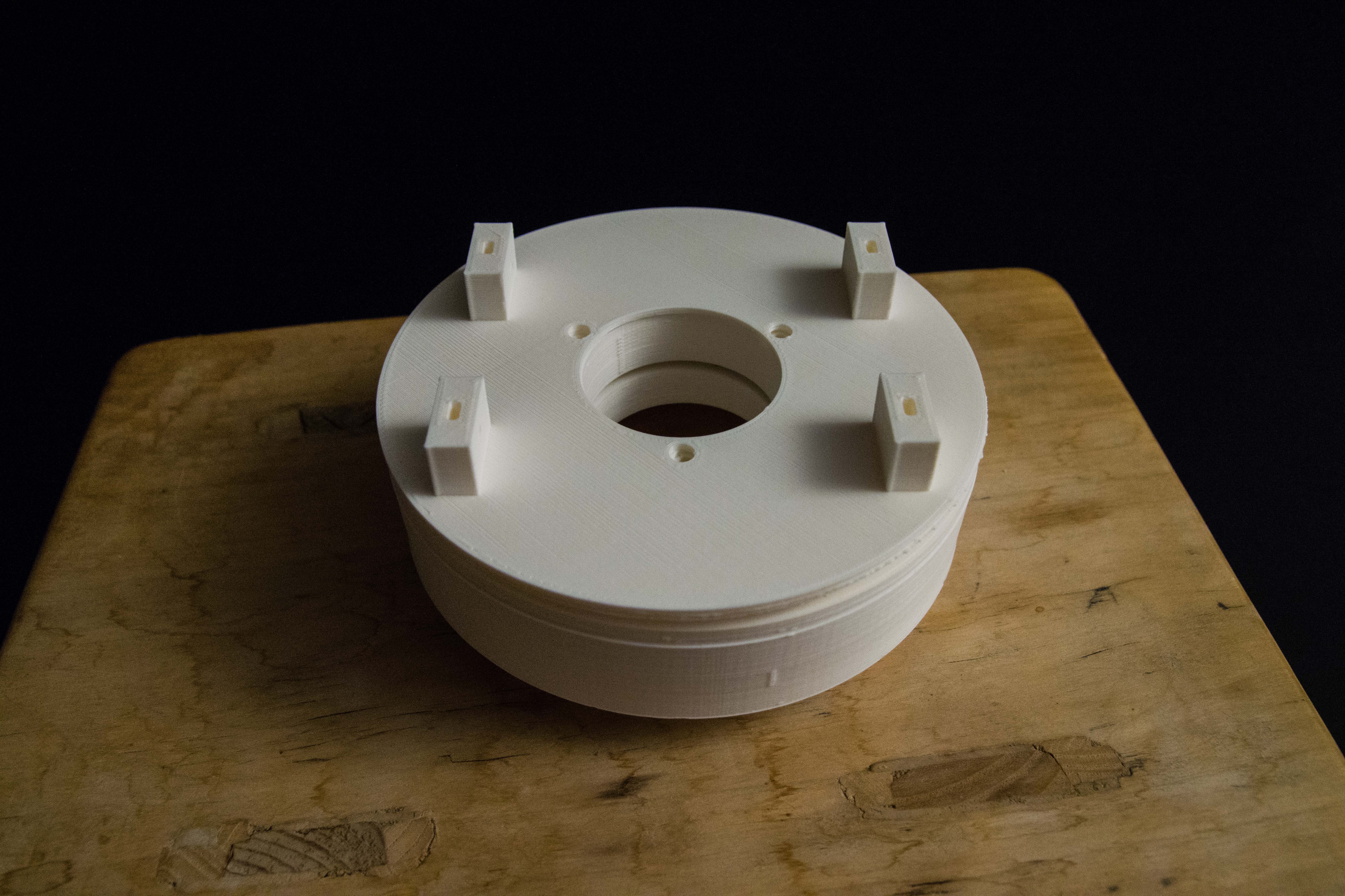
We have a big opening in the middle for wiring and 4 nut holders to screw on the upper part.
![]() This assembly goes onto the base.
This assembly goes onto the base.
Fully assembled base. The 3 big holes are places for the 3 stepper motors. That part must be reprinted because I can't squeeze the motors in. It appears that the 3D plastic is off with or 1 or 2 mm.![]()
Yes the upper part has also issue with broken off plastic. The walls are maybe too thin.
Building the Thor robot
Building a 6-axis robot based on the Thor robot. When size DOES matter!

 This assembly goes onto the base.