-
Steppermotor confusion (wiring colors)
12/25/2016 at 20:22 • 0 commentsI received a few of my DRV8825 to control my stepper motors but the wiring gets very confusing.
![]()
The setup is
- Ultratronics v1.0 Pro
- Stepper motor 17HS13-0404S
- Pololu DRV8825 Stepper Motor driver
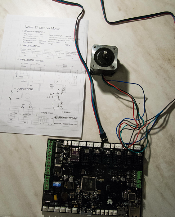
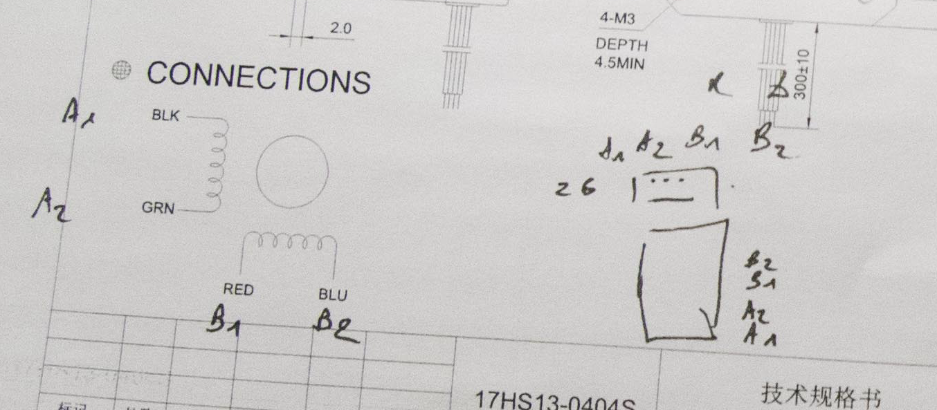
![]() The Stepper motor 17HS13-0404S documentation shows these wiring. Upper left.
The Stepper motor 17HS13-0404S documentation shows these wiring. Upper left.
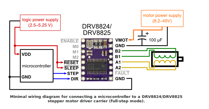
The Pololu DRV8825 Stepper Motor driver has this setup.![]()
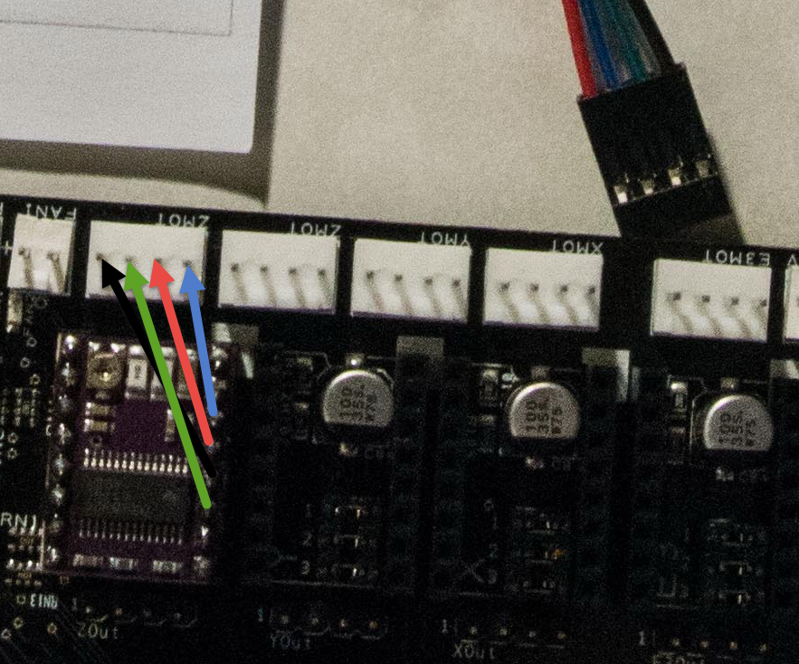
![]() Using my Ohm meter I discovered that the Ultratronics v1.0 Pro board has this sequence of connectors.
Using my Ohm meter I discovered that the Ultratronics v1.0 Pro board has this sequence of connectors.Left to right: A1 (black), A2 (Green), B1 (Red), B2 (Blue).
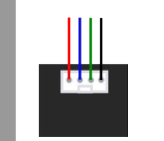
Note, the connector to the upper right that comes from the same company that ships the Ultratronics v1.0 Pro. Red and blue are reversed.
However the Ultratronics v1.0 documentation shows these colors for the connectors. Red and blue flipped and the connector should be reversed.![]()
Since I have never worked with a stepper motor before, it is going be trial and error to get the wiring correct. So I have to look out for smoke. LOL
UPDATE:
![]()
Comparison with the Ultratronics v1.0 documentation versus the Pololu DRV8825 documentation clearly shows a mixup with A1 And A2. I tend to trust the DRV8825 documentation as teh correct one.
-
MPU-6050 Accelerometer + Gyro
12/24/2016 at 15:51 • 0 commentsI didn't receive my RAMPS to control my stepper motors, nor important mechanical parts to assemble the Thor robot. so I am a bit stuck in development for the Thor.
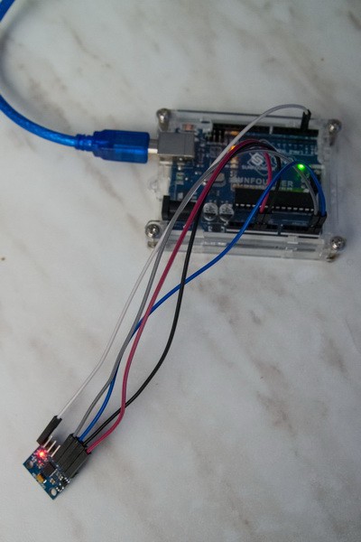
However I did receive my MPU-6050 accelerometer + gyroscope module so let's continue that path.
I was wondering an easy way to remote hand control the Thor robot when I discovered the MPU-6050 gyroscope. I am wondering if I can use that module in a way that I use the motion.
The Thor robot has to control 6 motors, and the goal is to make it dead easy to control with fluid movements. Joysticks are not very intuitive.
![]()
I am taking a Arduino Uno for this proof of concept but I most probably will use an Arduino Nano because I want it to be very compact.
The idea is to put the senor on a glove on my hand. The accelerometers used to control the robot using inverse kinetics. And using the Gyroscope to control the hand rotations.
To avoid an out of control robot when I scratch my nose I will have a second hand controller to be used by my other hand. I am thinking about a button to press with my thumb to activate the robot controls and when I release it, the robot stops in its position.
I am also thinking about having several buttons on the left hand control to change modes. fast pace, slow pace.....
These are concept ideas...
-
Art1body modification proposal
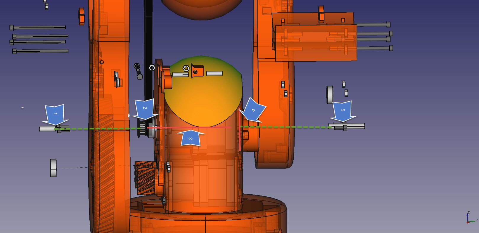
12/22/2016 at 21:46 • 2 commentsIf I understand the Thor drawing correctly then Art1Body has an rotation axis along this line.
The whole assembly is pushed together by the intersection (upper right)
![]()
The issue is that I have 2 small 5 mm rods and the motor axis that holds the complete weight. I am wondering if we cannot modify this design so that we have one solid rod and the driving motor shifted up or down with cogs in between.
This would remove the weigh off the stepper motor, and be much easier to montage and balance when it gets a full load.
I like the idea that the upper arm driving motor is in the lower base so that it the biggest weight of the motors is lower to the floor. And when they are together then we only need one cooling fan to cool all three motors.
The lower left motors work in tandem because of the power it needs to move the upper weight. I am wondering if one of the motors cog may be better positioned to opposite side and have a second inner cog at the right arm. That would improve the balance because we have current design has enormous horsepower on only on side, risking the arm to skew one side.
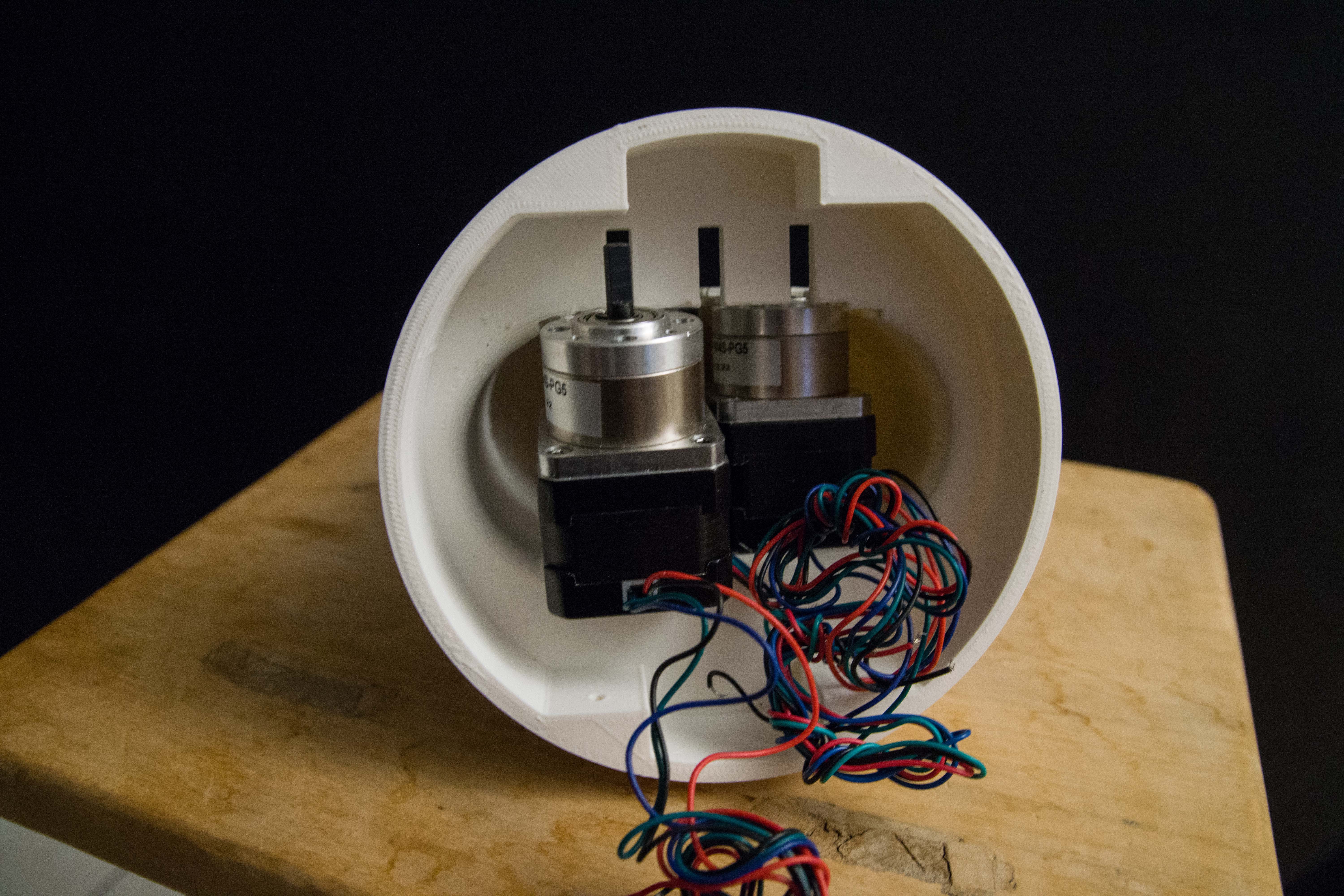
![]()
An example of the 3 motors inside the 3D printed housing as a test assembly.
-
Some setbacks and goals
12/21/2016 at 21:14 • 0 commentsSome setbacks no functional Thor robot this year.
My big ball bearing 16014zz 70mm x 110mm x 13mm was canceled by Amazon as undeliverable.
Also my Pololu DRV8825 Driver Carrie did not arrive yet som I have nothing to test my stepper motors.
I have a week of holidays coming up so I ordered 3 Pololu DRV8825 Driver Carries from a different source that I know that will receive in my free time.
My holiday plan is to try to create the control software that will control the motors. And the primary focus will be a reliable 7 motors movement at the same time. I want a fast and fluid moving robots!
Next stage, built restrictions in the software that takes into account acceleration, stepper and speed limits. The last thing you want is a self destructing Ninja robot. Or a robot that kills the payload due to acceleration.
Final stage would be make that code flexible enough to be used by controllers.
-
Ultratronics Pro v1.0: Programming setup
12/18/2016 at 02:03 • 0 commentsThe Thor project I am building will be based on a Ultratronics Pro v1.0.
I do not have any experience with this board at this moment, so it is a wild jump into programming it as a Arduino Due.
This board is very similar to the populair Megatronics board, but it has much more power due to the 32-bit Atmega SAM3X8E clocked at 84Mhz.
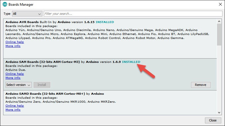
Go to Boards manager
![]()
You can use the Arduino software to program it, but you must install "Arduino SAM Boards (32-bits ARM Cortex-M3) by Arduino version 1.6.9"
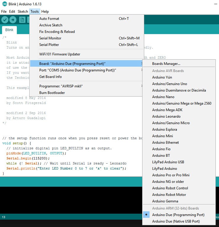
![]()
Now select the "Arduino Due (Programming Port)"
The controller board has 2 micro USB ports, one is the programming port the other one is a normal USB port.
I do not have any RAMPS yet to control my motors so I only tested with a on board LED blink and retrieve serial communication just like I would on a normal Arduino.
-
The motors arrived
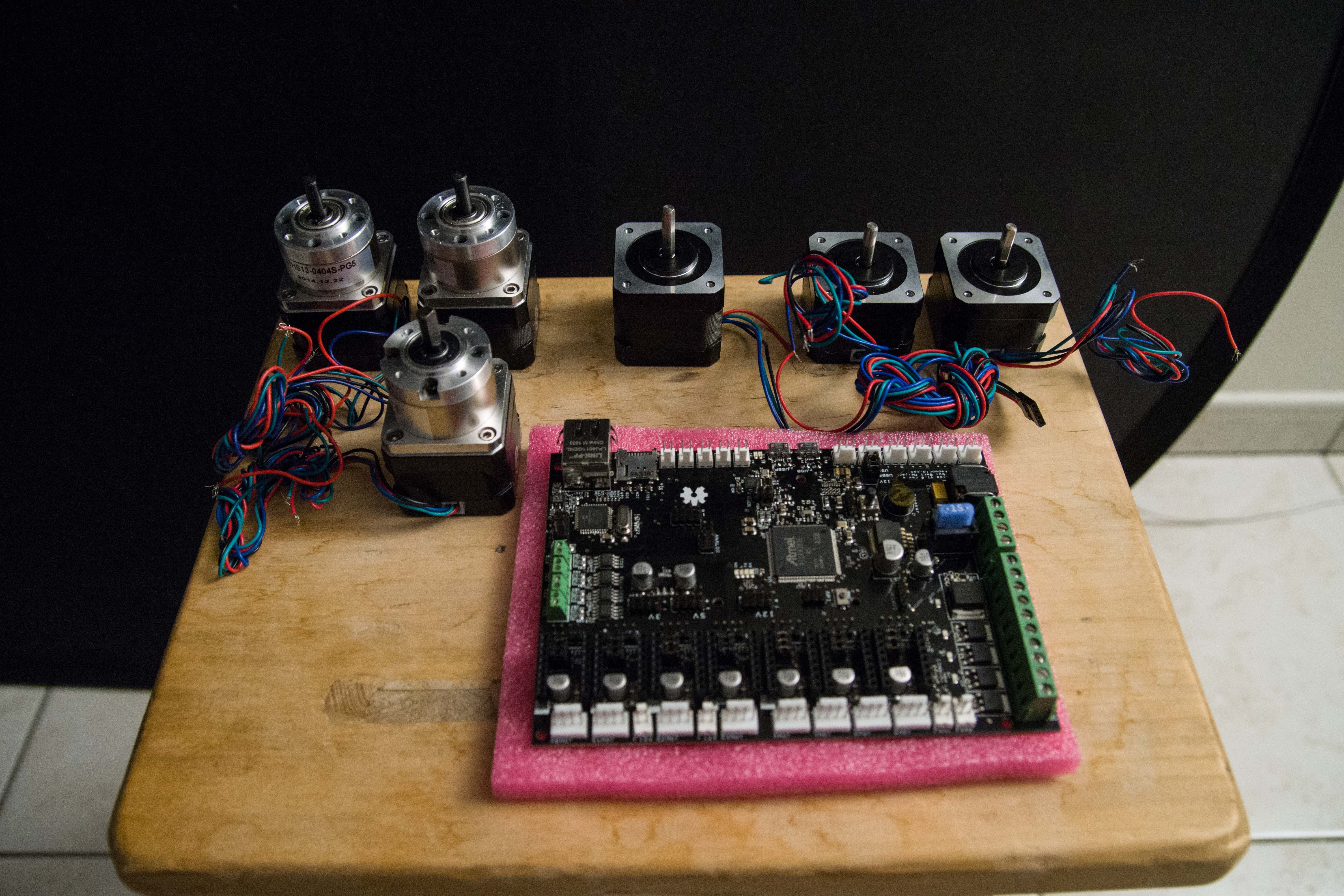
12/15/2016 at 21:39 • 0 commentsThe Thor motors are in.
Thor needs 7 of them. (One is missing on the family photo)
![]()
- Top left are 3 planetary gear motors to control the up and down arm movement.
- Middle top is the motor that will control the base.
- Right top are 2 motors to control the hand.
- One motor to rotate the upper arm(missing on the photo)
Also the main board to be used.
![]()
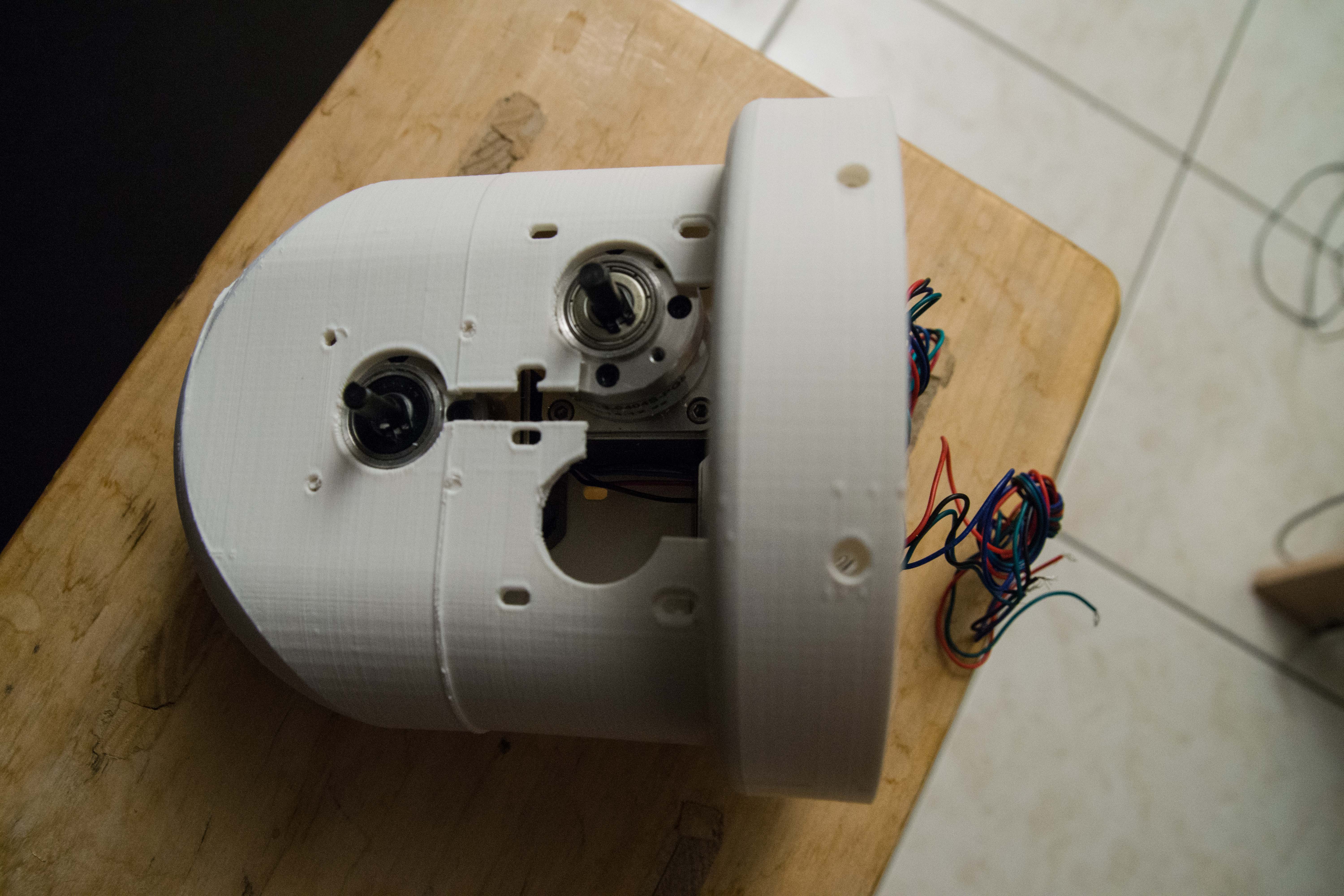
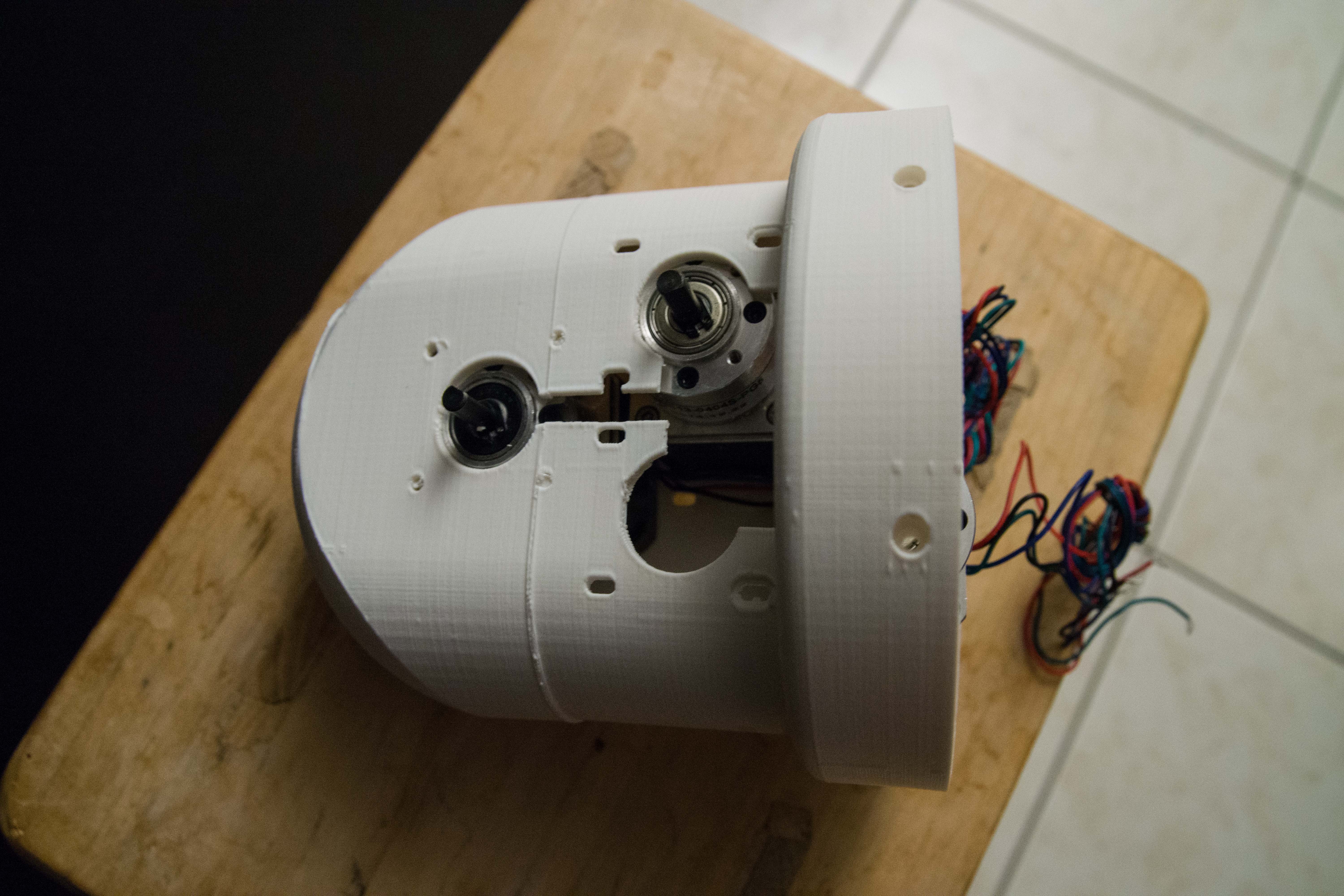
Trial assembly turns out to have an issue in getting the motors inside the housing. It is too tight.
The bottom 2 geared motors (on the right in this view) are going to work together as one pair because it has to support the complete arm.
This model was printed in multiple times and then glued together because the 3D printer had the Thermal Runaway issue and aborted the printing. I broke away some front parts to get the motors inside as a test. This part needs to be reprinted anyway.
![]()
The idea is to slit the motor down the opening.
Now that these 3 motors are inside the housing, I am wondering if we don't have a cooling problem now.
-
Thor main controller boards are in
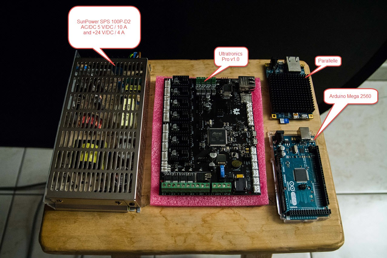
12/14/2016 at 21:51 • 0 commentsThe planned electronics that will become part of Thor.
![]()
Through advice of Danny I purchased a big enough power supply that can handle both 5V (10 A) and 24V (4 A) This one is €100. This may be overkill but the power supply can be recycled for future projects.
Bottom right was the original Arduino Mega 2560 that I wanted to use as a controller. But again from advice by Danny I went for the Ultrasonics v1.0 (€150). It has all the electronics parts for up to 7 RAMPS (must be bought separate). So no more additional wiring and print board needed for the controller.
Special note for the Parallella processor, that is a 16+2 core processor that kicks ass. This will probably be used in the Thor project when I do image recognition and signal processing.
Now waiting for the RAMPS and the motors to hit my mailbox.
-
Thor hand assembly trial: Very shaky
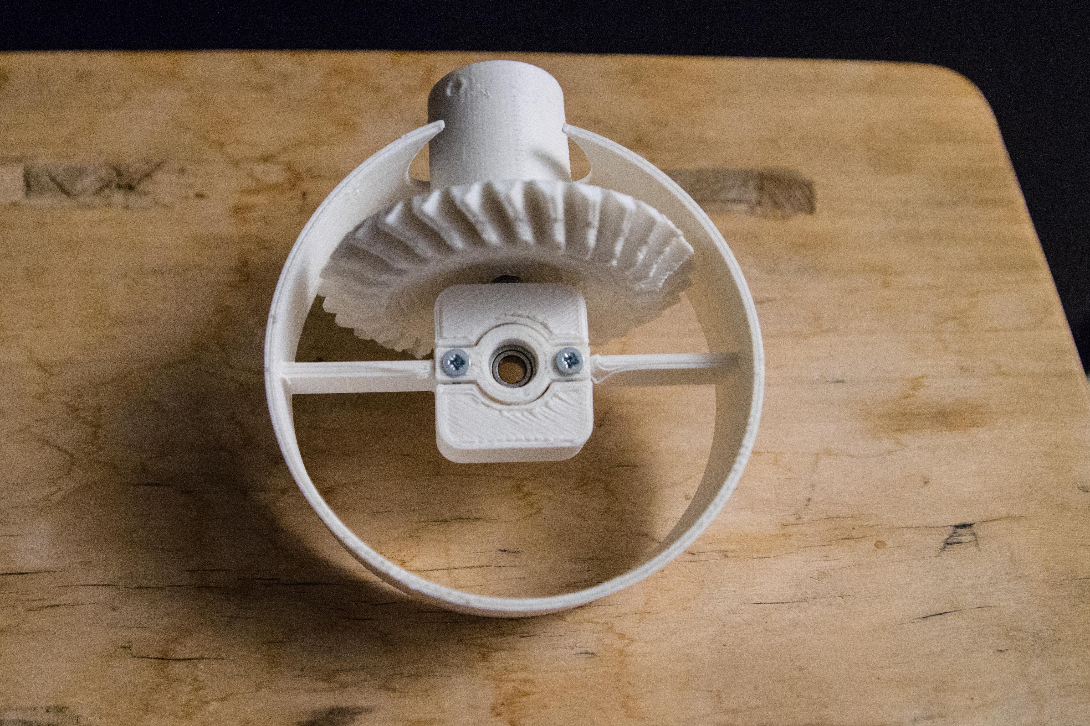
12/13/2016 at 21:35 • 0 commentsThis party is what is used to control the hand of the Thor robot but very unclear for me how to assemble it.
![]()
This is a trial assembly but it is very shaky even when assembled with the 90 degree cogs.
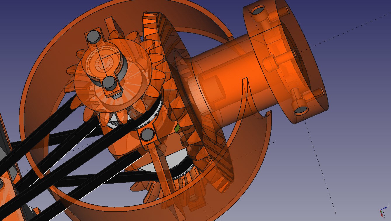
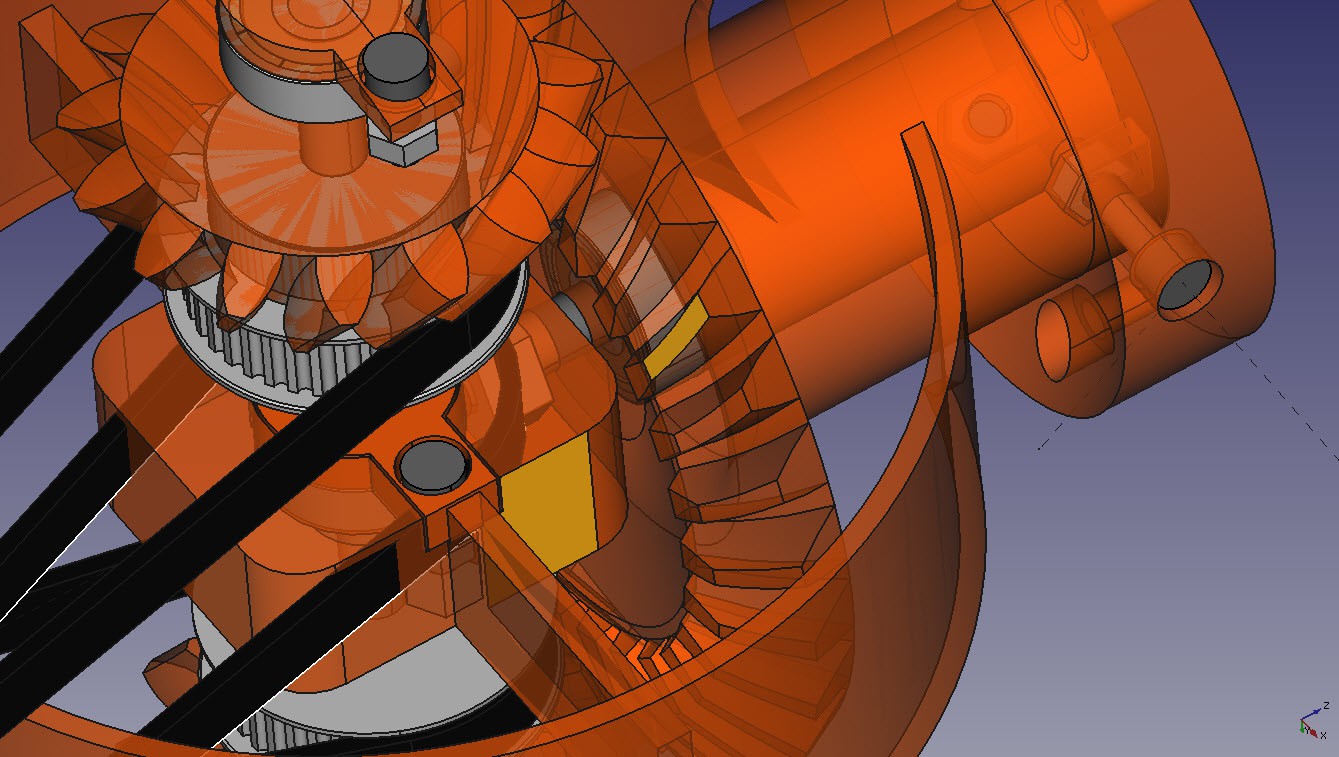
![]()
Inside there seems to be a ball bearing where the screw goes through it and the 90 degree cogs should push it up.
![]()
Here you can see that there is a screw just above the ball bearing of the axis.
-
Art4Body upper part assembly trial
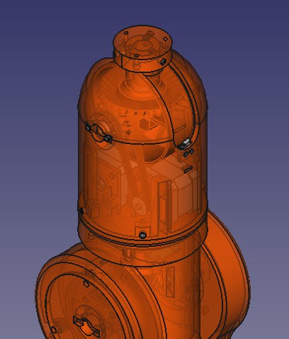
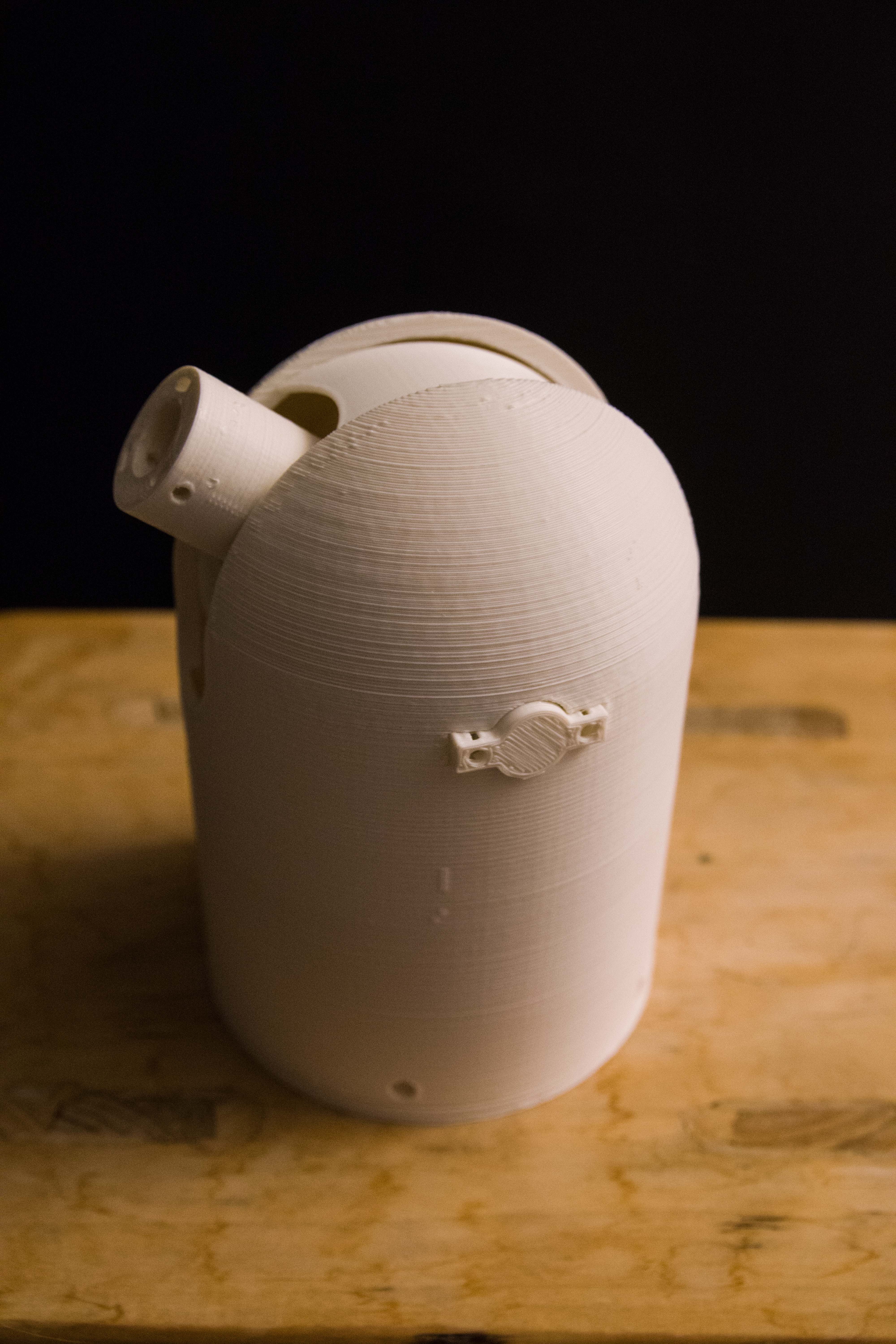
12/12/2016 at 20:58 • 1 commentThe upper part of the robot is Art4Body.
![]()
It consists of multiple parts that must be printed, an axis, ball bearings 2 motors, a electronic switch and a driving belt.
![]()
This is how the 3D printed version looks like. To get a sense of dimensions, it is 18 cm high.
The dome is printed separately since it needed support structures. To reduce printing time I printed the dome top separately decreasing printing time, then glued it together.
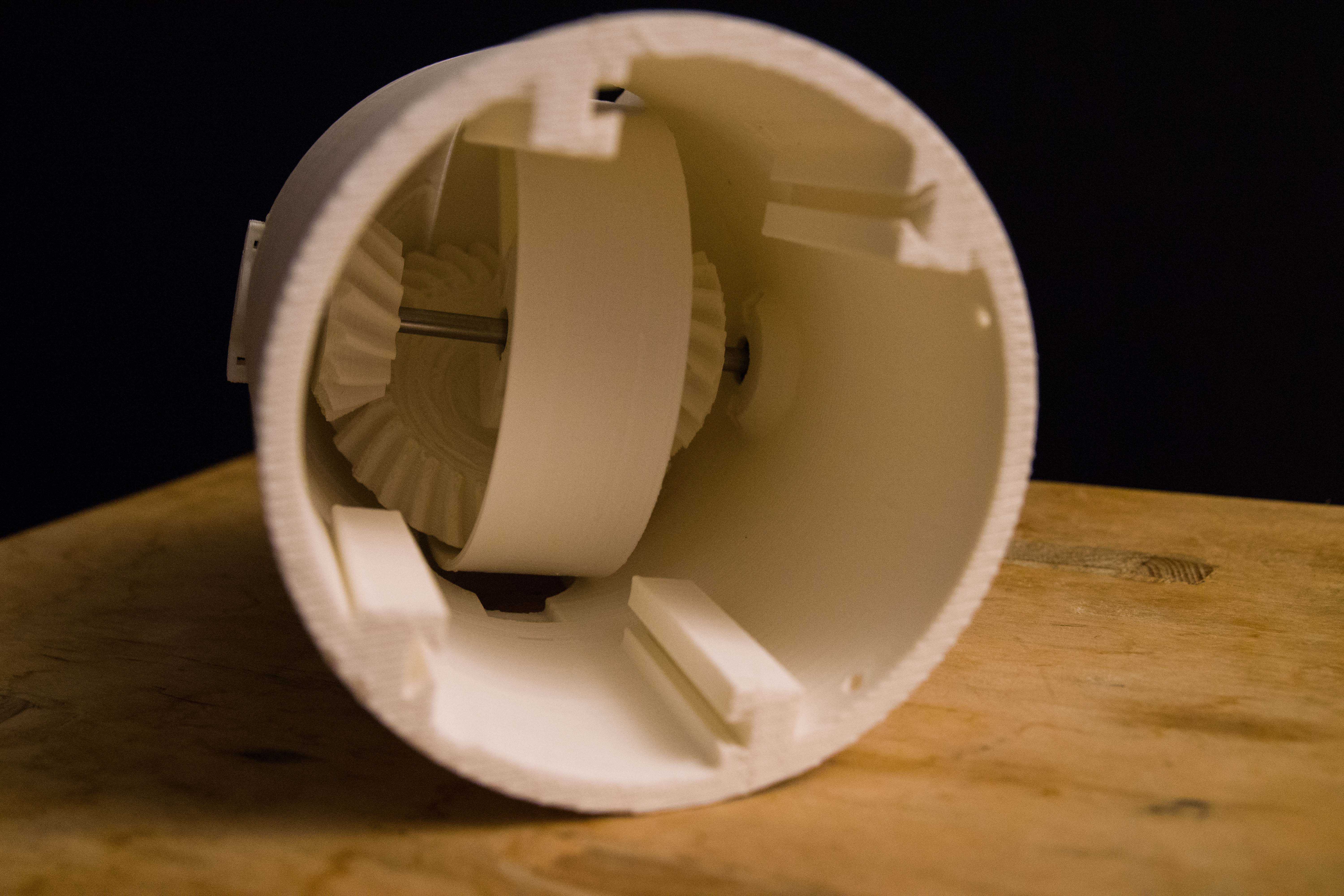
The axis is held in place by these ball bearing holders. They are not screwed in yet because I don't have all the parts yet.
An inside look to see how the parts works together. Still missing in this view are the pulleys that are driven by 2 motors and 2 belts. I still do not have these components.![]()
The idea is that if both motors move in the same direction then the hand gets up and down. When they move in opposite direction then they rotate the hand.
During assembly I discovered that it is not easy to assemble this part. I am wondering if that part cannot be redesigned so that it is easier to put together.
Also the hand part itself is not very clear how to assemble correctly. It appears pretty lose but more on that part later on.
-
Danny's Base_Fixed.stl
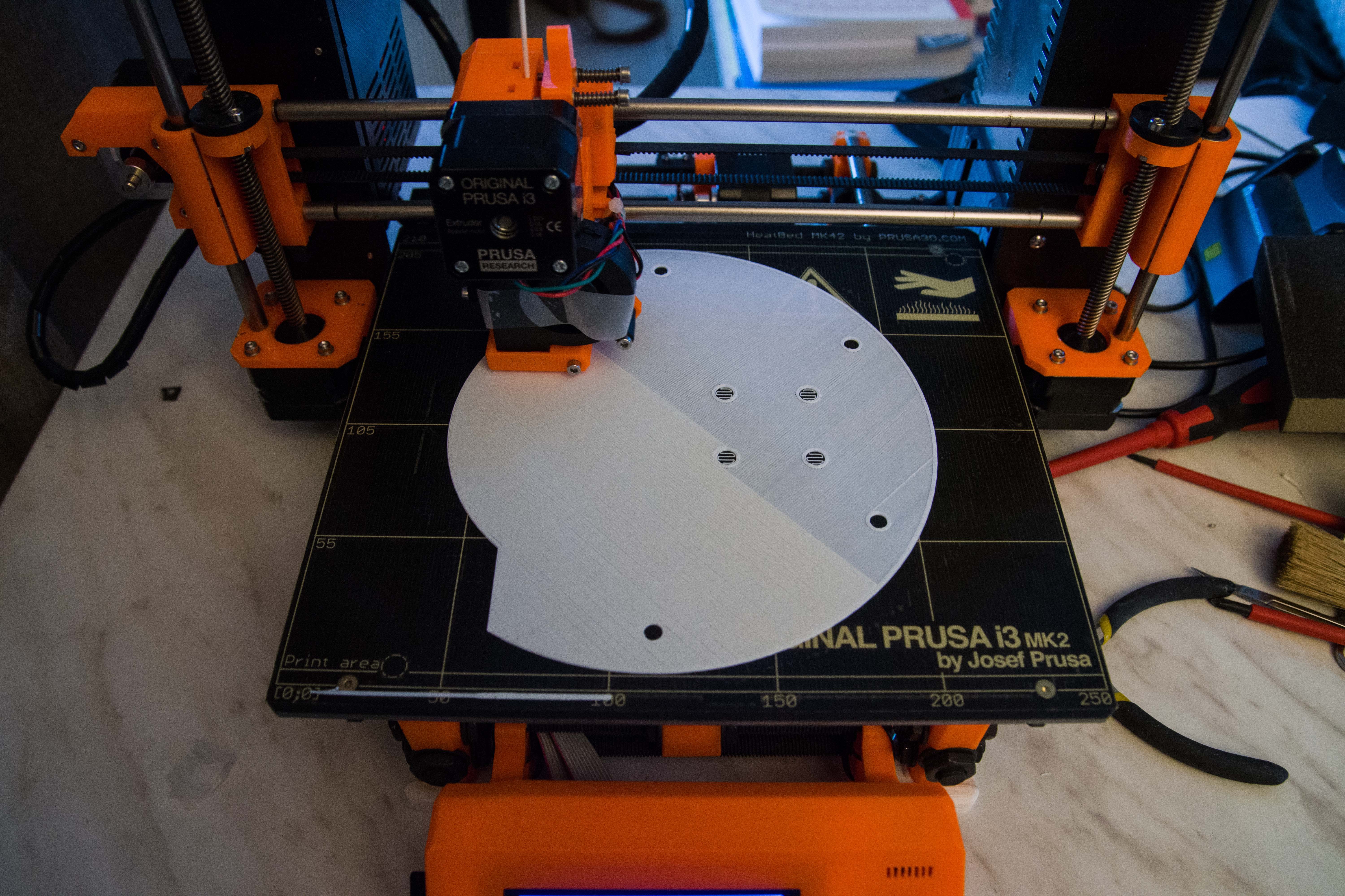
12/11/2016 at 21:31 • 1 commentThe Thor project is too big for my 3D printer so my Thor variant is a mixture of the original Thor project and Danny's modifications. For the base I have choose to use Base_Fixed.stl from Danny.
As you can see it juussst fits on my Prusa 3D printer.
This is the start of a 12 hour print job.
![]()
Take special note at the transparent tape at my extruder. It is put there to reduce air intake on the extruder ventilator that sends air to the model to cool down. It prevents a "Thermal Runaway" situation that actually halts my printing.
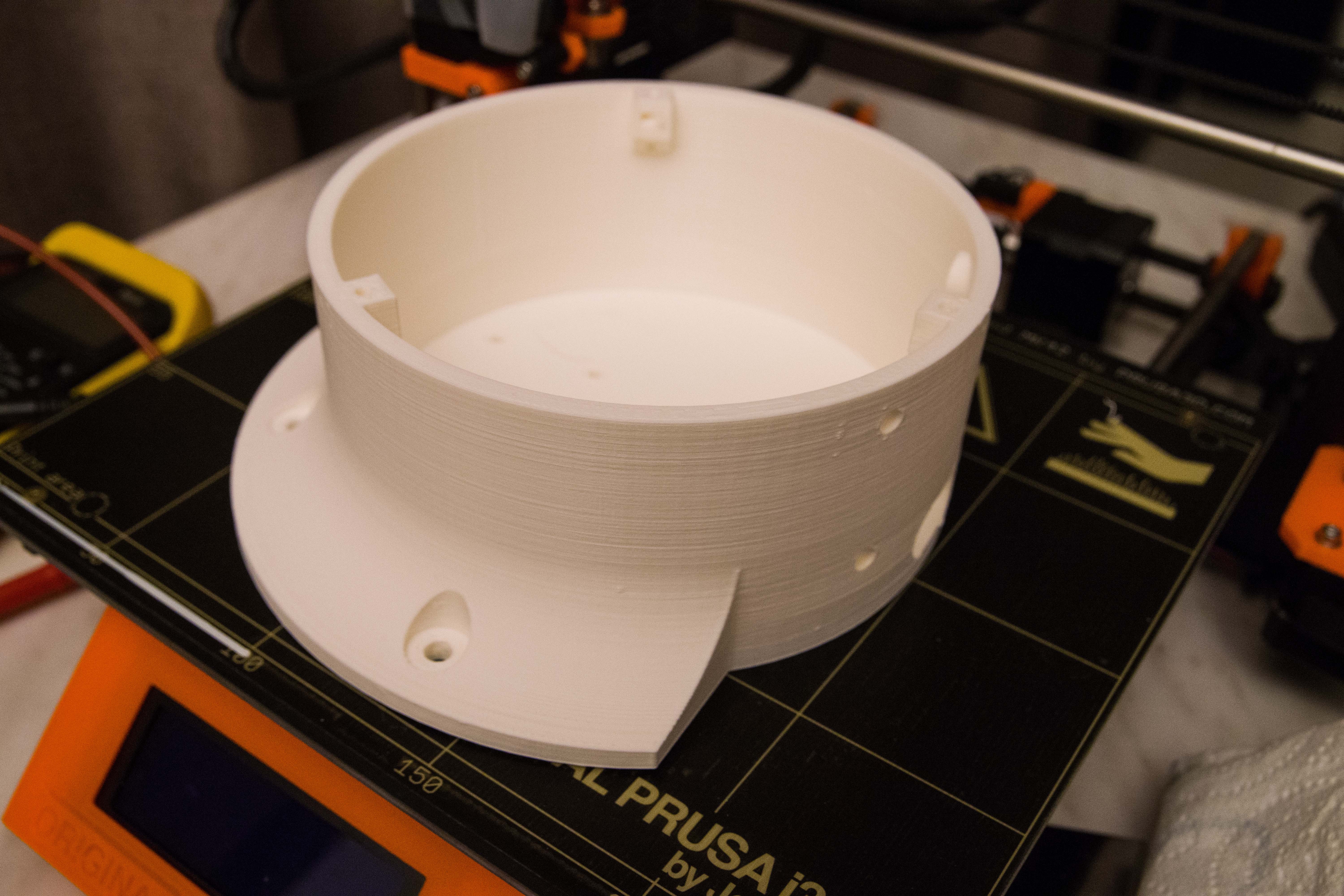
It seems that the Prusa's power supply is not strong enough to keep the extruder at 255 C and the heat bed at 100 C when the ventilator blows air on the model and cools down the extruder. (It depends of the size and shape of the model as far as I have noticed.)
![]()
After 12 hours and the transparent tape trick I had a perfect model just printed in one go.
Building the Thor robot
Building a 6-axis robot based on the Thor robot. When size DOES matter!
 The
The