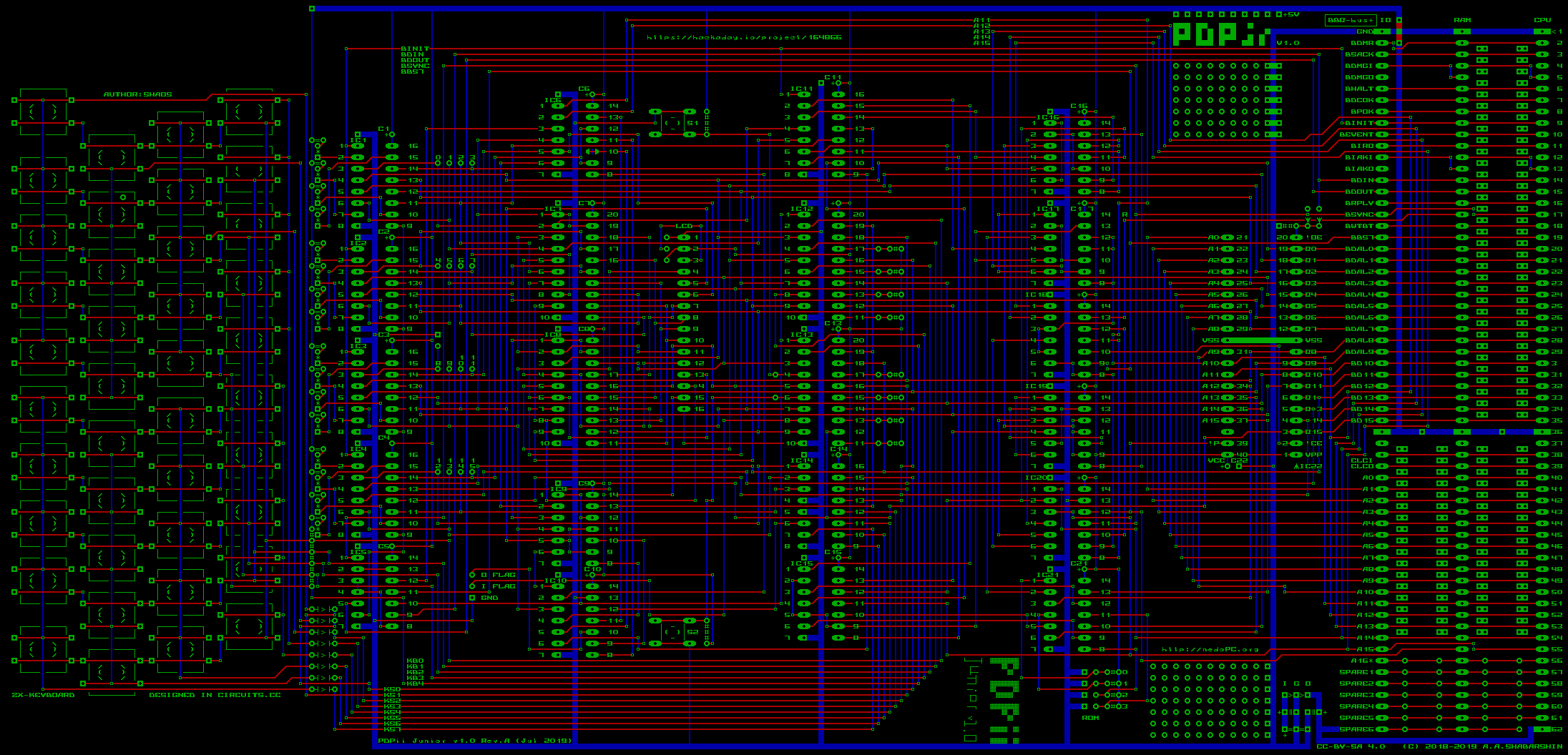
Finished main board design - it's 13.7 x 6.6 inches:

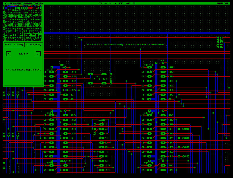
For the board I used the same Circuits.CC (my online tool for making simple schematics and PCB):

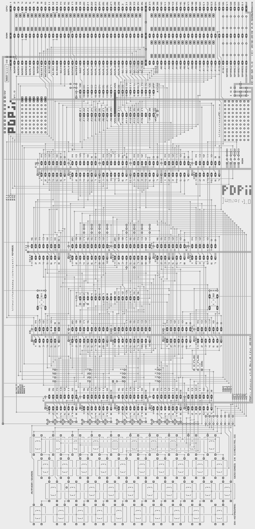
To make board image more readable I rotated it, moved to grayscale and inverted:

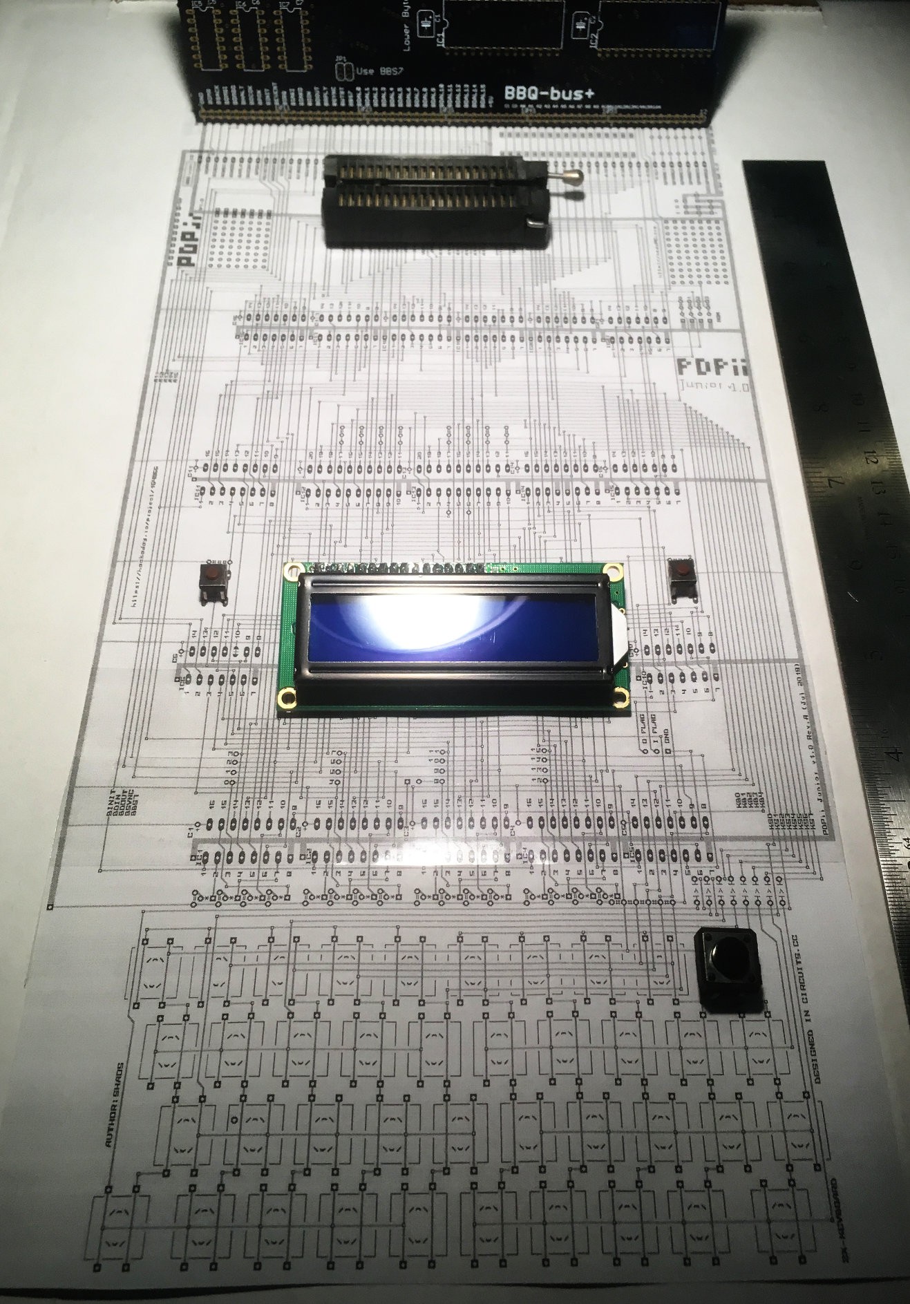
and even printed in scale (160 dpi) to see if components are fitting well ;)

Now I need to write C-program to convert my tiled pseudo-ASCII design to Gerbers for production ;)
P.S. Just noticed a few things to fix - probably 1st of all I need to write C-program that is looking for errors like interrupted wires. incomplete pads etc...
 SHAOS
SHAOS
Discussions
Become a Hackaday.io Member
Create an account to leave a comment. Already have an account? Log In.
Wow, I didn't even know PCBs can or were designed that way, with the ASCII. That's really cool. Nice board too, by the way!
Are you sure? yes | no
Thanks :)
Actually it's slightly extended ASCII ;)
1st 30 characters were specifically changed to help construct PCB-like images
And last 14 characters are helping with schematics :)
Are you sure? yes | no
That makes sense. Seems similar to the Propeller chip's ROM font. Just a random and absurd thought, but perhaps circuits.cc could be ported to a microcontroller like the propeller. XD Sorry, just had to throw that out there. :P
Are you sure? yes | no
Yes, it could :)
Significant portion of Circuits.CC is written in Robby programming language ( also mine ; )
See https://gitlab.com/shaos/circuits_cc/blob/master/src/CIRCUITS.R
And Robby has cross-compiler for Intel 8080, z80 targeting ZX-Spectrum and a few Russian retro-computers and it's relatively easy to add more target platforms / processors - see #nedoPC SDK
Are you sure? yes | no