Original #PDPii memory modules occupy these address ranges:
- nedoPC-18.10 aka "ROM module 64KWord or 128KB" - 0x0000...0x7FFF or 0x0000...0xFFFF (paging with jumpers);
- nedoPC-18.20 aka "RAM module 32KB" - 0x8000...0xDFFF or 0x8000...0xFFFF (use or ignore /BBS7).
Here I will not use ROM module, because ROM chip 27C1024 will be on motherboard itself with programmable paging (16 pages ROM0...ROM15 8KB each). RAM module will be inserted into dedicated BBQ-slot and split to RAM0 and RAM1 halves (16KB each) that will be connected to memory windows independently with help of some additional logic. So I plan to have 3 BBQ-sockets on that motherboard:
- BBQ-bus+ socket for CPU module;
- BBQ-bus+ socket for RAM module (this socket will be customized BBQ-socket just for RAM);
- BBQ-bus+ socket for any I/O module controllable by /BBS7 signal (for example RC2014 adapter).
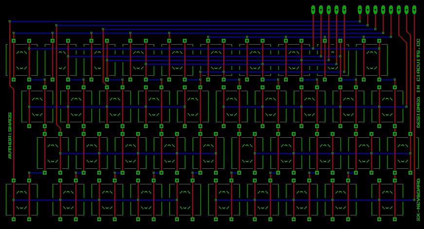
Also motherboard will have 16-bit register (probably better to take 4 x 74LS175 to have ability to use inverted bits and clear it on RESET) and 16-bit buffer (inverting 2 x 74LS240) to write/read LCD accessible by address 0xFF00 (or 0177400 in octal system that was "native" for PDP-11). For keyboard addressing it will be 74LS138 decoder chip that converts 3-bit address to 8 control lines (and we will read 5 signals back from keyboard - similar to classic ZX-Spectrum):

For bank switching we can take 4-bit register and make it accessible with some combination of control bits when LCD is disabled. That bank switching latch will encode memory mode:
| Memory mode | Window 0 0x000...0x3FFF | Window 1 0x4000...0x7FFF | Window 2 0x8000...0xBFFF | 1st half of Win3 0xC000...0xDFFF |
| 0000 | ROM0 + ROM1 | RAM1 | RAM0 | ROM0 |
| 0001 | RAM0 | RAM1 | ROM0 + ROM1 | ROM1 |
| 0010 | RAM0 | RAM1 | ROM0 + ROM1 | ROM2 |
| 0011 | RAM0 | RAM1 | ROM0 + ROM1 | ROM3 |
| 0100 | RAM0 | RAM1 | ROM0 + ROM1 | ROM4 |
| 0101 | RAM0 | RAM1 | ROM0 + ROM1 | ROM5 |
| 0110 | RAM0 | RAM1 | ROM0 + ROM1 | ROM6 |
| 0111 | RAM0 | RAM1 | ROM0 + ROM1 | ROM7 |
| 1000 | RAM0 | RAM1 | ROM0 + ROM1 | ROM8 |
| 1001 | RAM0 | RAM1 | ROM0 + ROM1 | ROM9 |
| 1010 | RAM0 | RAM1 | ROM0 + ROM1 | ROM10 |
| 1011 | RAM0 | RAM1 | ROM0 + ROM1 | ROM11 |
| 1100 | RAM0 | RAM1 | ROM0 + ROM1 | ROM12 |
| 1101 | RAM0 | RAM1 | ROM0 + ROM1 | ROM13 |
| 1110 | RAM0 | RAM1 | ROM0 + ROM1 | ROM14 |
| 1111 | RAM0 | RAM1 | ROM0 + ROM1 | ROM15 |
On reset it will be memory mode 0000 (ROM in window 0 then RAM1 then RAM0) then BIOS will programmatically switch memory mode to something else to have RAM in the 1st half of memory to be able to run RT-11 apps and 1st half of Window 3 will be used to access other ROM pages. 2nd half of Window 3 will always be BBS7 area for peripheral devices inserted into 3rd slot. Also it is possible to add 4 jumper switches to mix ROM pages to start from any ROM page if needed (for debug purposes for example).
Description of every bit of memory location 0xFF00 (LCD control register and keyboard reading):
| Bit | On write | On read |
| 0 | LCD data bit 0 (also goes to bank register) | LCD data bit 0 |
| 1 | LCD data bit 1 (also goes to bank register) | LCD data bit 1 |
| 2 | LCD data bit 2 (also goes to bank register) | LCD data bit 2 |
| 3 | LCD data bit 3 (also goes to bank register) | LCD data bit 3 |
| 4 | LCD data bit 4 | LCD data bit 4 |
| 5 | LCD data bit 5 | LCD data bit 5 |
| 6 | LCD data bit 6 | LCD data bit 6 |
| 7 | LCD data bit 7 | LCD data bit 7 |
| 8 | LED output (error) and may be sound (?) | Keyboard data bit KB0 |
| 9 | LCD control input RS (0 - command, 1 - data) | Keyboard data bit KB1 |
| 10 | LCD control input R/W (0 - write, 1 - read) | Keyboard data bit KB2 |
| 11 | LCD control input E (0 - disable LCD, 1 - enable LCD) | Keyboard data bit KB3 |
| 12 | Keyboard address bit KA0 | Keyboard data bit KB4 |
| 13 | Keyboard address bit KA1 | Extra button S1 (?) |
| 14 | Keyboard address bit KA2 | Extra button S2 (?) |
| 15 | Extra output (goes to bank register if E=0 and RS=0) | Extra input (reserved for future use) |
 SHAOS
SHAOS
Discussions
Become a Hackaday.io Member
Create an account to leave a comment. Already have an account? Log In.
To write something into bank switching register we should set E (bit 11) and RS (bit 9) to 0 and then bit 15 to 1 - in this case bank switching register will store bits 0...5 (bits 4 and 5 will be ignored for now).
Are you sure? yes | no