This project follow the same philosophy of our previous project I2C Encoder.
This project is based on the TSWB-3N-CB222 LFS from C&K
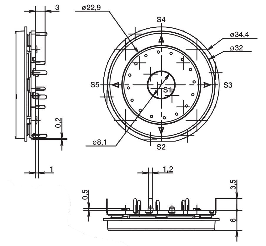
It is a 7 function joypad with 4 directional keys, central button and a scroll wheel.
The PIC16F18345 from Microchip makes it possible to use this joypad with the I2C bus, in the same way of the I2C Encoder.
Feature:
- I2C bus works up to 400kHz,
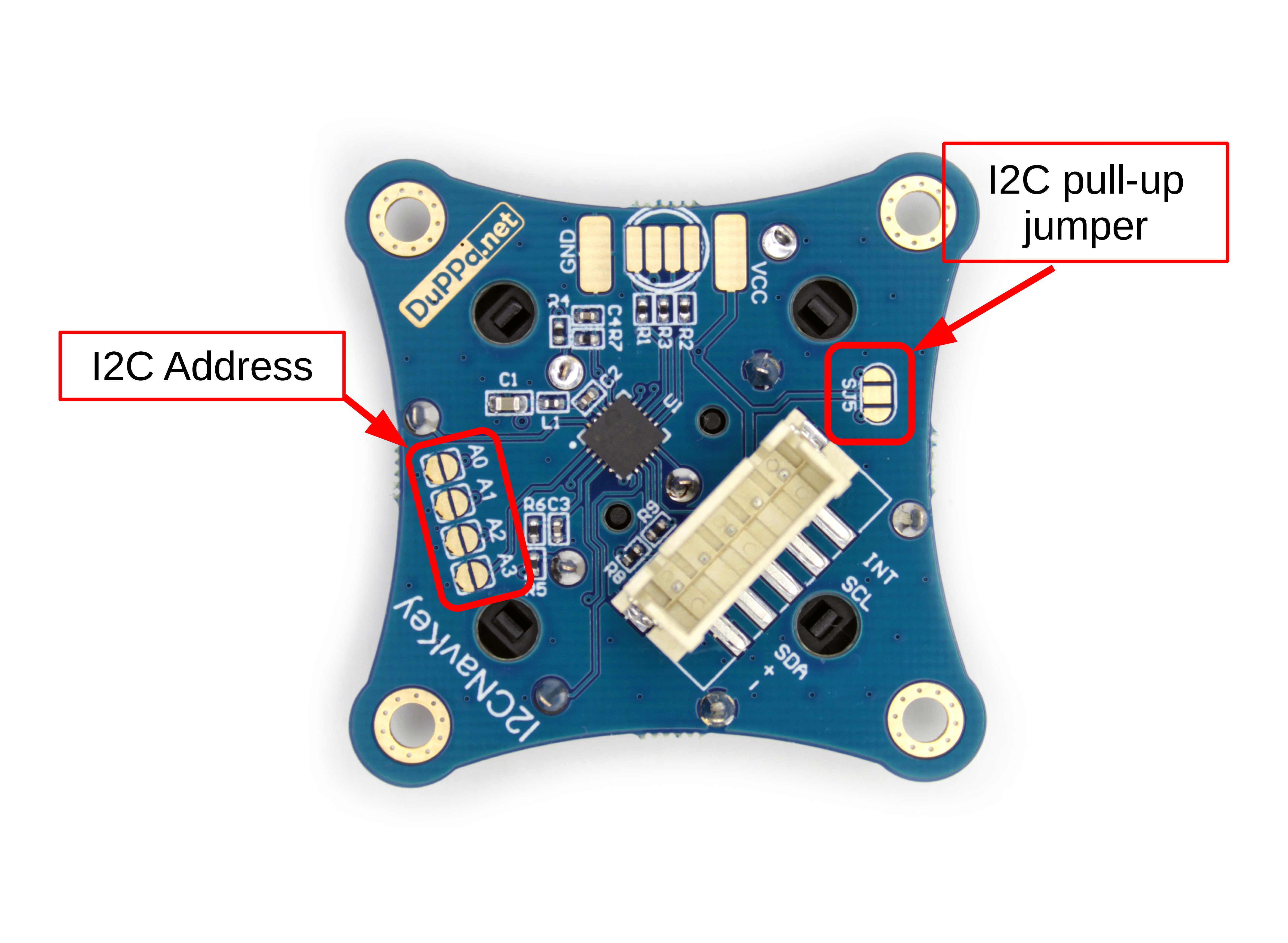
- Possibility to add the pull-up resistors on the I2C bus.
- Possibility to customize the I2C address by soldering the 4 SMD jumpers
- Open-drain Interrupt output pin, so no need to continuously poll the devices
- There is a 5 pins JST-XH header
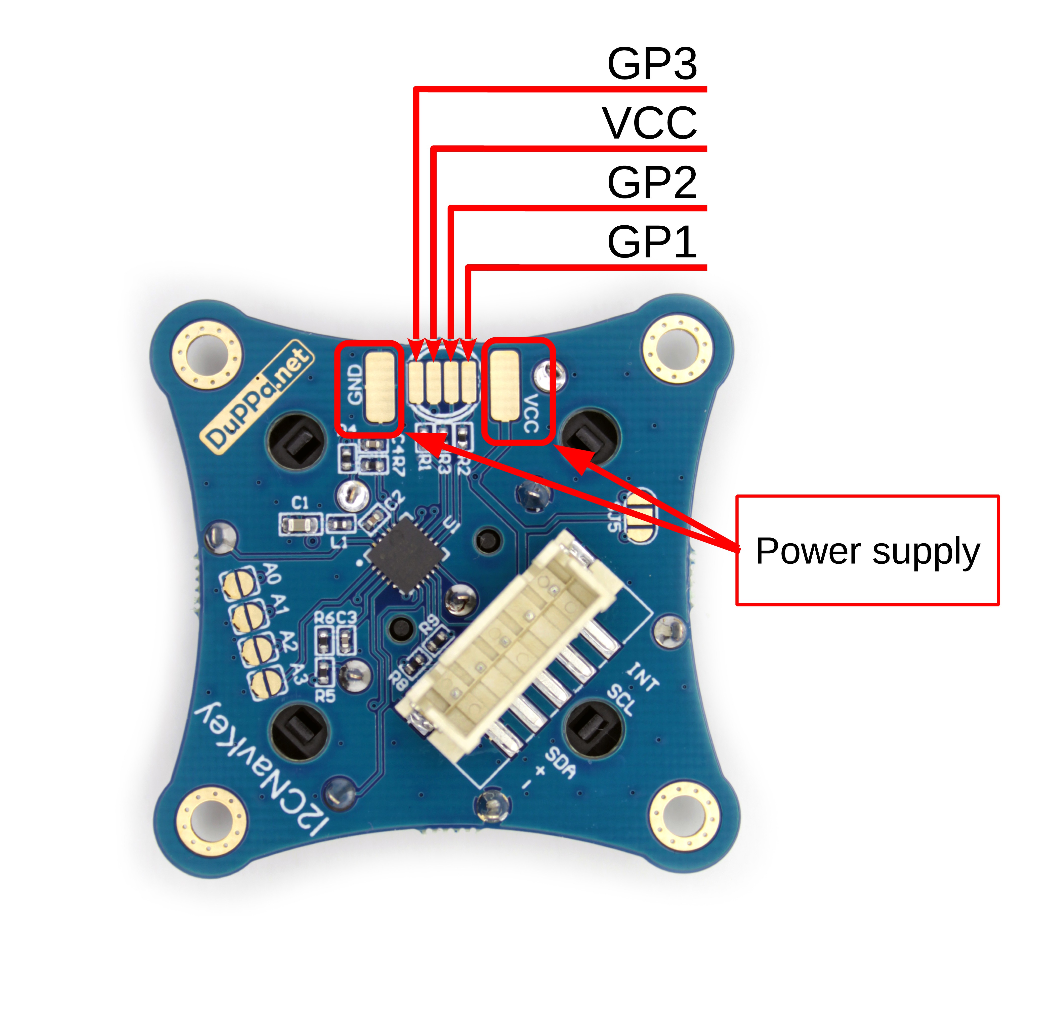
- There are 3 General Purpose pins. (GP pins)
- 256 byte of internal EEPROM divided into 2 banks of 128 byte
- Voltage range is 2.5V to 5V
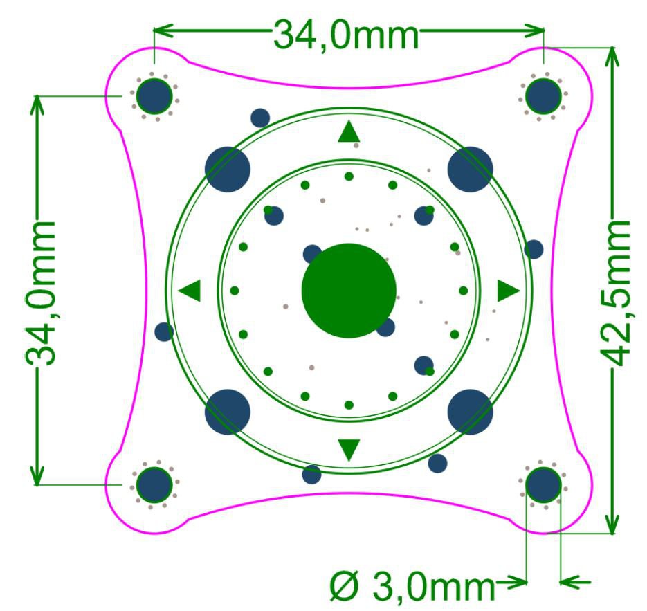
- Dimension of the device is 42.5x42.5mm or 1.67x1.67in
- 4 mounting holes with 3mm diameter
- Open source firmware
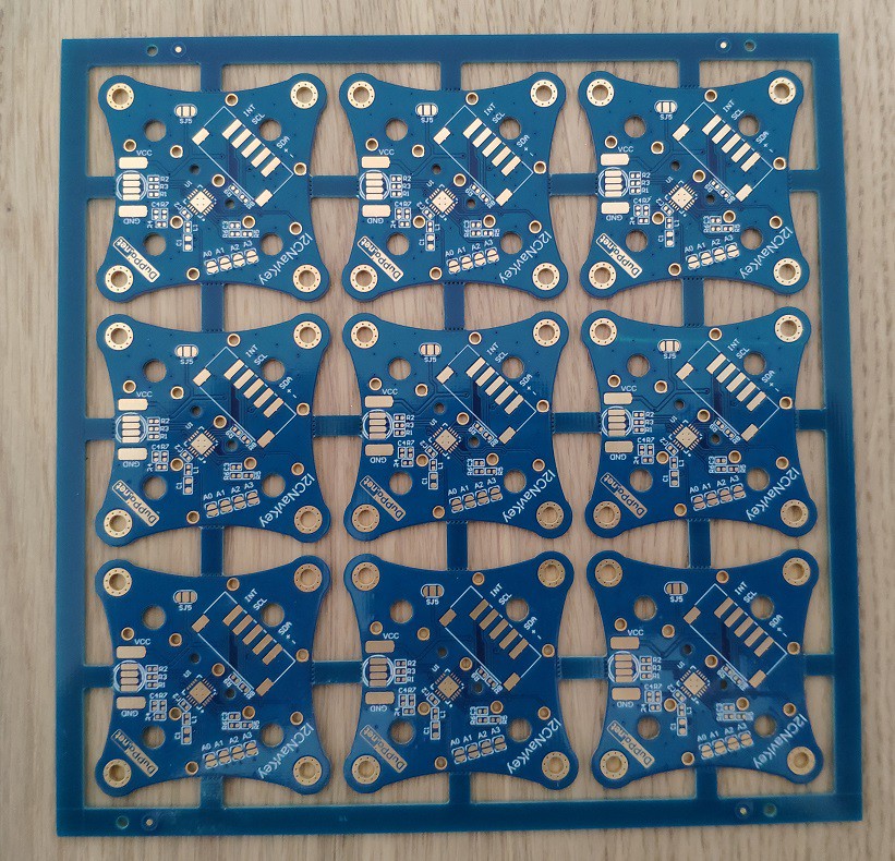
The board is 42.5 x 42.5 mm and it has 4 mounting holes. On the top layer, there is no components, this make perfect for mounting on a panel near of a LCD display.
On the bottom side, there are all the components, plus the connector.
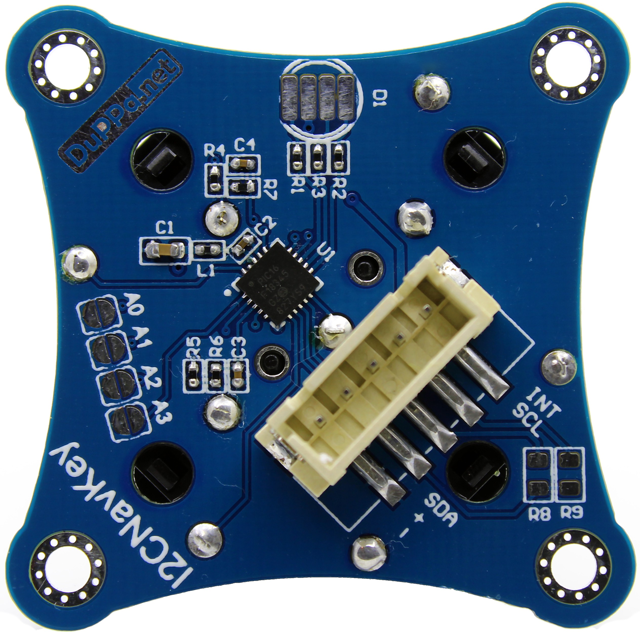
The connector is a common 5 pins JST-XH, it is very easy to find some cheap cable already crimped.
The I2C NAvKey is a I2C slave. On the bottom side, there are 4 SMD jumpers where is possible to set the I2C address.
Like other I2C devices, it has a series of 8 bit registers:
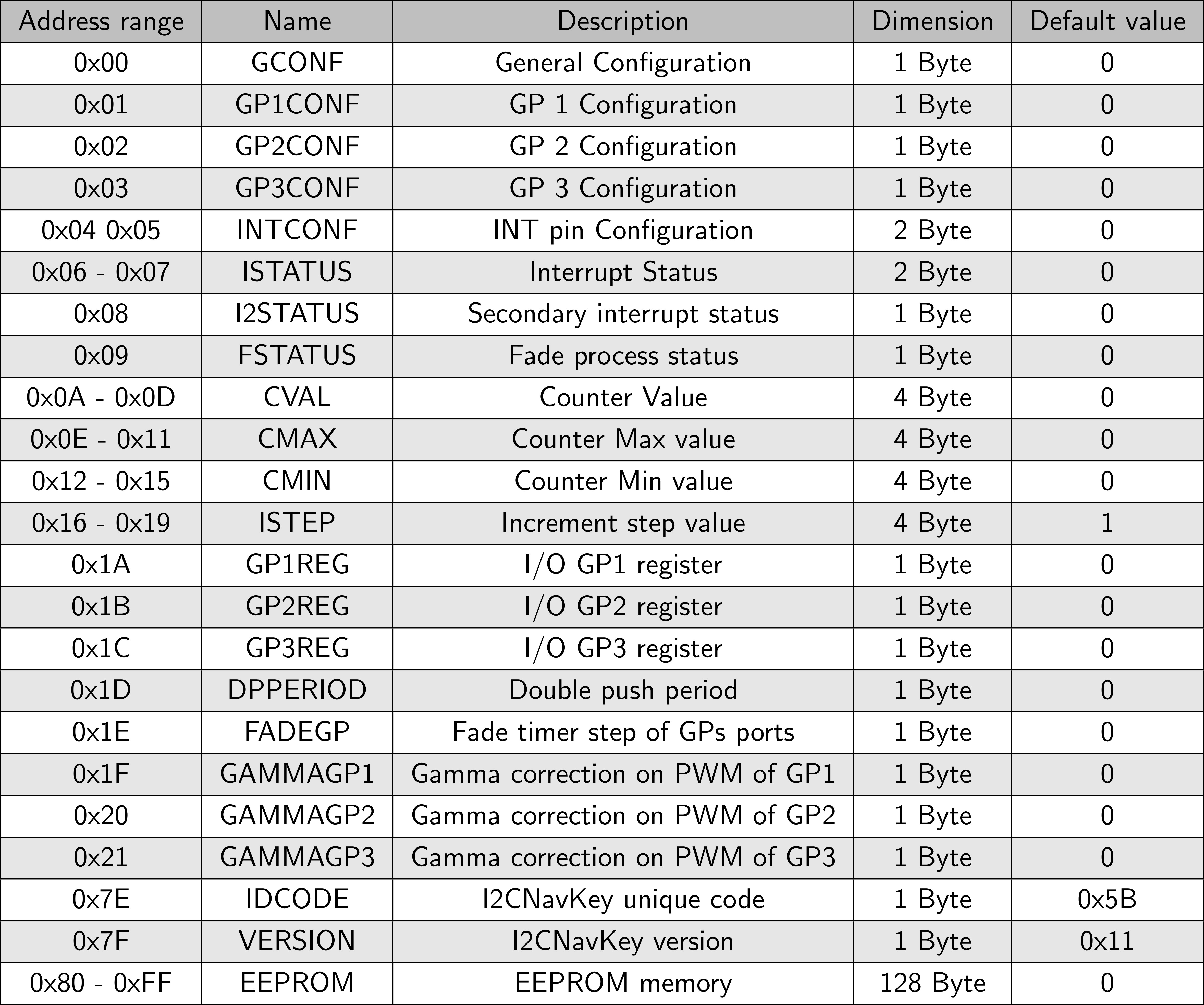
With these registers, it is possible to use configure and use the device. Most of the functions are similar to the I2C Encoder especially the encoder part.
In the I2C NavKey, it is also possible to enable or disable the I2C clock stretch and there are also a register with a identifier (IDCODE) and another with the version. (VERSION).
GP pins
Like the I2C Encoder, also the I2C NavKey has the 3 GP pins. They work at the same way of the I2C Encoder.
Each GP pin can be configured in the following way:
- Digital output
- Digital input, with the possibility to enable the interrupts on the edge change
- Analog input, with a resolution of 8bit
- PWM output
The PWM mode is completely different from the I2C Encoder.
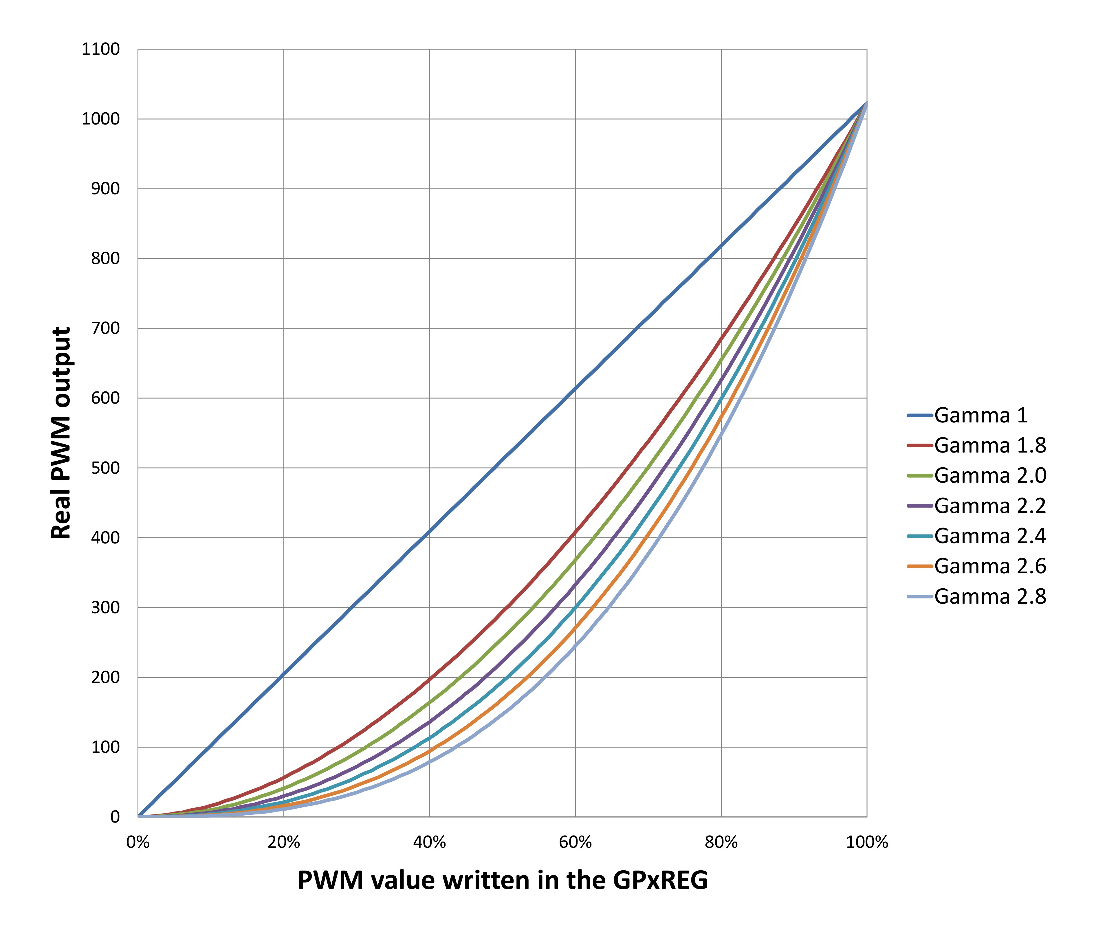
In the I2C Encoder is just a raw 8bit PWM, in the I2C NavKey is configured in 10bit mode, but the user can set the duty cycle only from 0 to 100 (0% to 100%) plus can configure a 7 types of gamma correction.
The gamma correction is very useful if a LED is used. Because it makes the LED intensity more linear to the human eye.
 Saimon


 Hulk
Hulk
 greg
greg
 Ken Yap
I received this great device a few months ago, and didn't try it immediatly. Yesterday, I connected it to my Smart Remote Control (https://wiki.logre.eu/index.php/Télécommande_intelligente_2) but I'm unable to communicate with it. Even i2cdetect does not see it (default address 0x20). But my I²C master works fine with many other devices.
How can I debug it? Are there some pins to check to see if the PIC is running? BTW, SCL and SDA are OK, they are not held to ground or something...
Thanks for your help.