 Marcos
-
Schematic released!
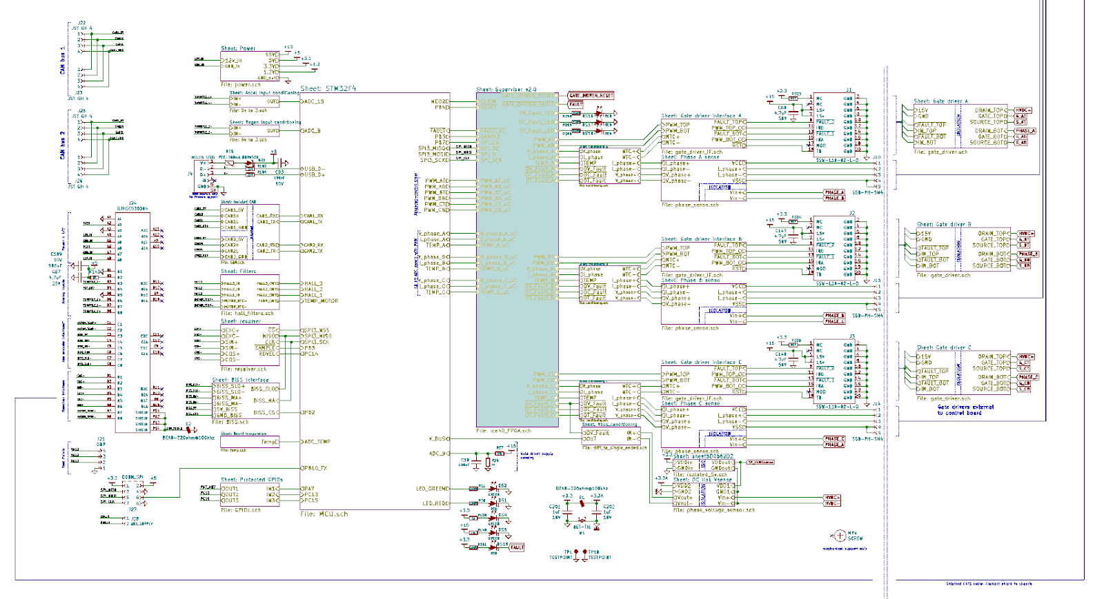
08/22/2019 at 03:18 • 0 commentsIt took us long enough, but we have finally converged to a releasable schematic!
Take a look for yourself:
http://www.powerdesigns.ca/files/Axiom_Rev1_schematic.pdf
I really don't remember seeing a schematic this complete, clear, complex, and public! Most of the team worked at aerospace and military organizations, so we know a thing or two about these documents and that experience was put into practice here. It is released under a Creative Commons BY-SA license.
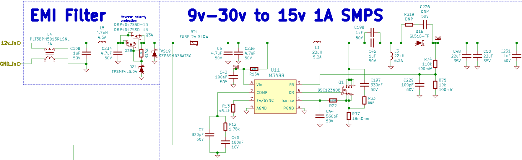
Take for example a simple component like any of these capacitors.
Is the capacitance important? Of course! Is the rated voltage important? You bet!
A wrong capacitance value can be harmless, or detune a timing or filtering circuit. But using a 6.3Vdc capacitor on a 15Vdc rail will have dire consequences, hence the need to be verbose when drawing the schematic and be clear about the used ratings. You don't see this often in public schematics.
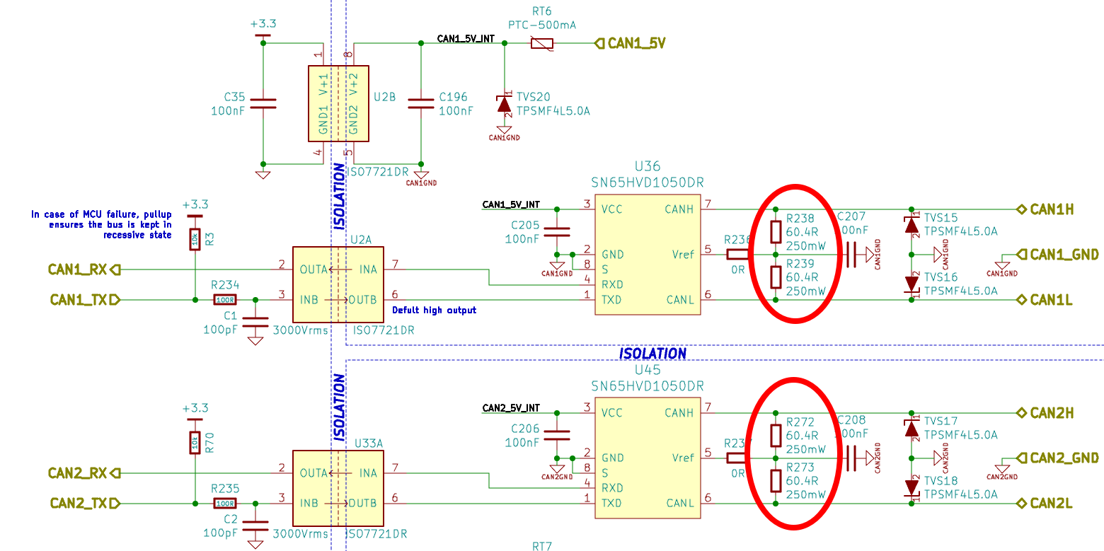
Resistors power rating present us a similar case. Take for example the CANbus termination resistor:
Can it withstand a continuous bus failure? If we are clear about the power ratings we can see that the termination resistor pair can take 500mW.
5V on a 120 Ohm resistor gives 208mW, so it should be alright. The DC Link discharge circuit needs to pass this continuous bleed check, with some extra safety consideration regarding discharge time.
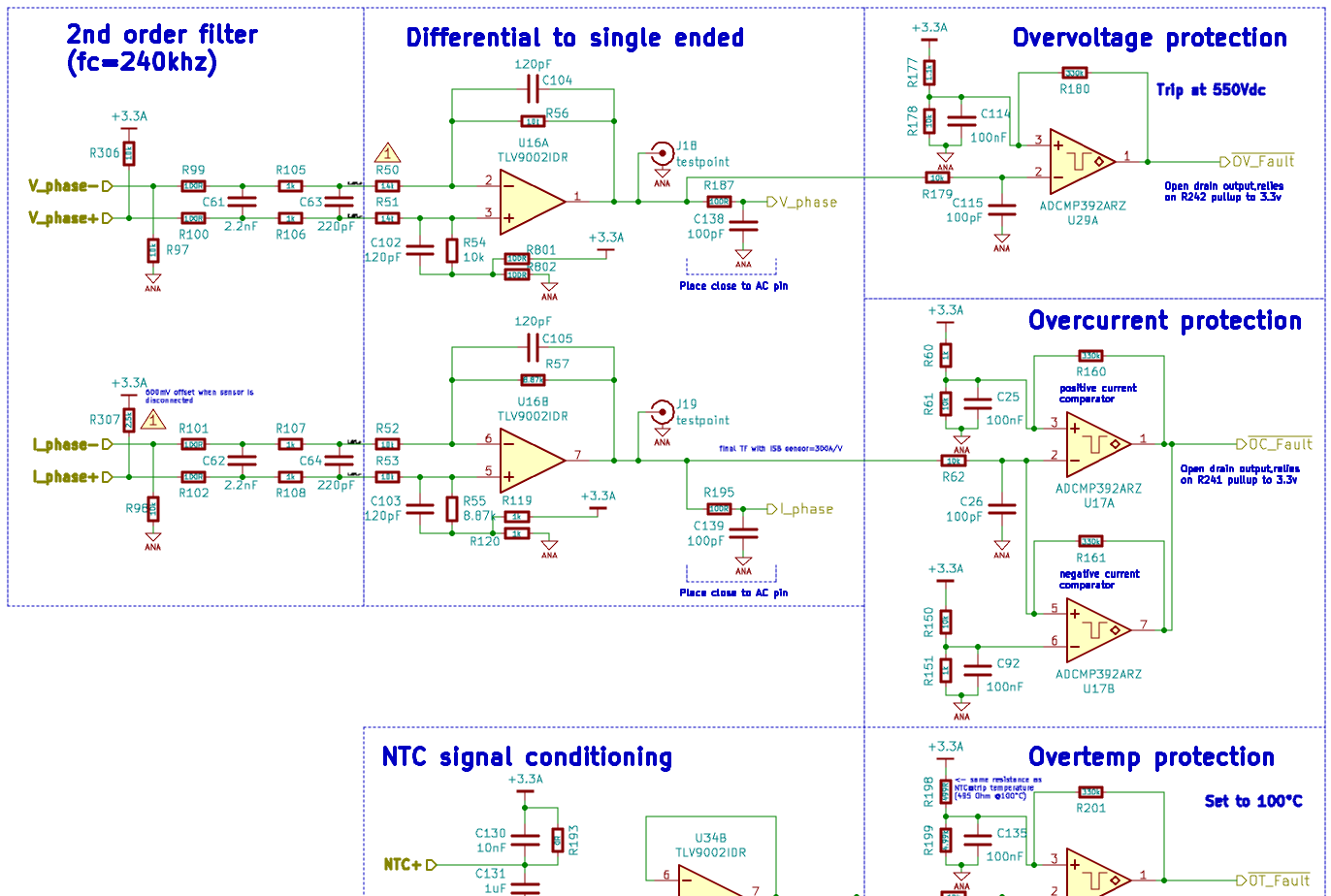
Then you have the more common practice of drawing the signal flow from left to right, for example in the signal conditioning circuit (there is one of these blocks for each phase):
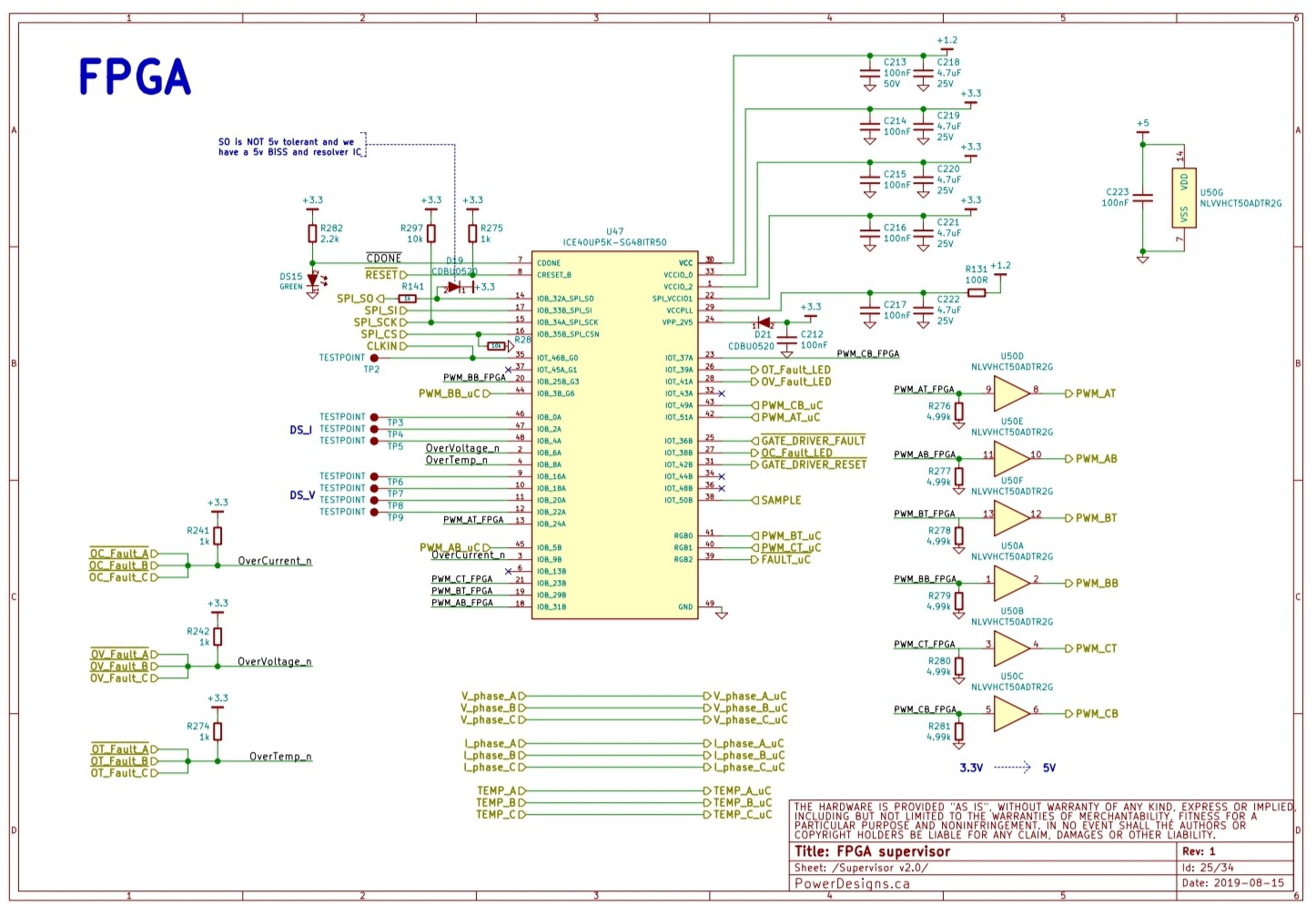
Many people asked about the FPGA implementation, and its a straightforward one.
![]()
It is configured over SPI, pwm signals are level shifted from 3.3V to 5V for better integrity under high EMI. The SPI bus can be used for high speed general purpose communication between MCU and FPGA. The ice40up5k eval board had some errors that were fixed in Axiom schematic regarding PLL supply filtering and power supply sequencing.
So there you have, an earth-shattering, high quality 34 page document meant to bring electric vehicles and high power motor control closer to everyone!
PS: Schematic was first released days ago to our newsletter subscribers. Subscribe now to hear first about Axiom news!
-
Design Decisions Philosophy
08/17/2019 at 03:41 • 2 commentsYou can have it good, fast, or cheap. Pick any two. Good and fast, it will be reliable but expensive to design. Fast and cheap, probably going to end up with something that causes fires rather than drives an EV. Cheap and Good is possible but it’s going to take some time to deliver. Obviously there are many design decisions made along the way of producing a final schematic and bill of materials for a high performance full up motor controller. But how are those decisions made? That is the focus of this log post.
And it turns out.. it's not that hard. During the initial project meeting EV Power Designs asks the client what are their top three priorities. Cost, weight, volume, performance, reliability, protection from obsolescence, manufacturability, time to market and so on. OK, I lied. It's hard; because after all don’t we want it all? Pick only three? This simple question tends to bring out a lot of discussion about the client’s expectations, desires, goals and general philosophy. The client gets to hear about how each design objective will influence the actual product so there is an appreciation both ways. Client and consultant get an opportunity to better understand the project but more importantly, each other. From this conversation, the three .. yes only three.. top priorities will eventually be ascertained.
Here is an example of how narrowing down the product development philosophy to three key drivers can help with decision making. Let's say the three most important goals are Weight / Volume / Cost (typical for new power electronics design where time to market is not a key factor). How does this impact the decision for torque control, arguably the most important function of a motor drive? Depending on the power level there are a lot of different design paths that will lead to lower weight, volume and cost but at all power levels it's possible to reduce the phase current sensor count from three to two. The motor load is still 3-phase, but the current in only two of three phases is measured for control purposes. The current sensor required for high performance motor drive is relatively expensive because it must be high bandwidth and low error so removing one out of the system saves a lot of cost. And the thing is rather large and heavy because of the internal ferrite core, so weight and volume come down as well. It's a win… win and win. but. As my old professor used to say, you never get a free lunch in engineering. There is a small price to pay to have higher performing op-amps that are now required for adequate design purposes, and with only two sensors the system will never be aware of circulating currents and thus never have the ability to eek out some more performance by nulling out the circulating current. Or in other words… with only two sensors, the system just became lower performance. Thankfully, in this example, performance wasn’t one of the top three design goals.
We applied this same philosophy to the Axiom control board design process. What three top priority goals should we have? Performance, reliability and versatility.
-
Dear Judges
08/06/2019 at 20:21 • 0 commentsDear Judges
It’s tough to get through hundreds of projects, here is some help!
i. Is this a unique solution to a particular challenge facing the world today?
There are lots of motor controllers out there, good, bad and ugly.
There are few motor controllers capable of moving a car.
There are no open source motor controllers capable of moving a car and pushing the boundaries and reach of electric vehicle technology like Axiom does.
And the world certainly needs to get good at this, motors are driving our civilization and comprise most of the energy usage, we need to accelerate our motor control tech. The best way to drive the technology forward is to open it up to the world, open source, and let all the clever and hyper interested people join together in one reliable, high power, high performance, flexible platform we’ve called Axiom.
ii. How thoroughly documented were the design process & design decisions?
I’m sure you’ve already read the project logs and really appreciate the magnitude of our work. The core work of the Axiom project is the schematic, bill of materials and main processor firmware; all open source. Although it only took a few weeks to generate the schematic and bill of materials, they are based on nearly two decades of intense professional design for high performance electric vehicles as well as commercial and military aircraft. In fact, the team members came together on a side project (managed by Arlin Sansome) to help with some of the motor control technology elements to push the boundary beyond reasonable limits, directly into world record breaking limits. Needless to say there is a wealth of experience on the team which allows for generating working schematics in a short period of time. The design itself is heavily documented. Simulation using Matlab/Simulink and PSpice helps to define circuit functional basics to system integration. MathCAD/Smath was used for much of the advanced analysis such as electrical stress, component sensitivity and tolerance analysis.
iii. How ready is this design be taken to market?
Several individuals, companies and universities are already stretching the muscles of their Axiom drives. We have been selling beta boards and complete controllers for a few months now to get early feedback while simultaneously building up some operational hours to prove out the design. We are expecting to take the product to market in 2020 for turn key 100kW motor drive power.
iv. How complete is the project?
Axiom is a complex convergence of mechanical engineering, electrical engineering, thermals, firmware, software, safety, racing, distributed work, user interface, artwork and the will to meet the most challenging requirements.
The Axiom control board product is already complete, working to control a limited number of high powered motor drives all over the world and will be available with all the bells and whistles in a complete high power, high performance, full up motor drive in 2020.
Finals
i. Concept- Is the project creative, original, functional, and pushing boundaries? Does the project benefit society in some way?
Axiom sports a creative assembly to simplify the production, it's been proven by many customers, not to mention the thousands of smaller controllers out there using the same VESC software we use and contribute to, and it is fueling the boldest high power applications not only electric cars but also turbogenerators, bikes, ROVs, big machinery and more.
If Axiom succeeds in its quest, the whole world will become better at spinning motors -one of the major energy consumers-. Pushing the boundaries is exactly where the Axiom product positions itself. An earlier version of the hardware broke the world record for fastest front wheel drive car on the ¼ mile¹. In fact, Arlin is currently working on the next iteration using Axiom to reaching higher and pushing boundaries further²
1. https://www.facebook.com/DailyPlanet/videos/1528421110540389/
2. https://hackaday.io/project/164932-axiom-100kw-motor-controller/log/165414-episode-iv-a-new-hope
ii. Design- Is there a depth of design detail available (like a system design, CAD models, project test methods, etc)? Is there base-level planning for the functionality (eg: functional block diagram, list of specifications and how they will be met, etc.)? How user-friendly is the design?
Glad you asked! Block diagram, schematic, enclosure, powerstage validation, safety mechanisms, a datasheet outlining the specifications and application notes describing how it all works in a full up controller. But that’s not all, there’s also an awesome open source graphical user interface (GUI) making motor setup easy and providing tools for deep data analysis.
The electronic bits of the full up motor drive are established. What we are still working on is how to package the product such that it is quick to assemble while remaining visually stunning.
iii. Production- Is the project reproducible (consider materials, skills, and processes)? Are the manufacturing processes detailed? Are those processes realistic for scalability?
Axiom has been designed from the ground up to be easy to assemble, reducing wiring, parts and streamlining the setup of each unit.
A single sided control board, its friendly bill of materials, and very standard manufacturing processes are in place for production. The Axiom control board is already in limited production, populated and tested using automated means. The control board is designed for drop in place into the full up motor drive to be offered by EV Power Designs Inc. Ease of assembly is paramount to long term success as a product. We are currently working on good packaging so that the Axiom control board can be quick ‘drop in’ installed along with all the other components that make up the complete motor drive.
iv. Benchmark- How well is the project impact and viability demonstrated? Are estimated costs realistic? Are direct, indirect, and future competitors clearly identified?
The best way to gauge axiom success is with the sheer amount of requests, multiplied by the fact of being in a premium and high margins market. The Axiom control board has exact pricing for producing in batches of 10, fully populated, firmware loaded and product tested. The full up motor drive, which uses Axiom control board, also has a completed bill of materials with exact pricing, assembly and functional test costs included. The only part of the full of 100kW motor drive that has not yet been confirmed is the mechanical enclosure but we have some promising quotes.
In terms of viability, the best proof is if there are interested buyers in many markets. We get requests for pricing and availability every day from individuals working on a hobby project to large corporations looking to jump start their R&D division. We take this as a positive sign of product viability.
There is really no need to compete with low prices, as Axiom simply delivers better what the market needs: a powerful and reliable motor controller that can be deeply tuned to your needs.
v. Communication- How thoroughly have the final round requirements been completed? How well documented is the project? How “Open” is the design? Is the project marketable?
Documentation is key for our customers so we have a datasheet, a full schematic available, bill of materials, 3D models and 150.000 lines of open source firmware, software and toolchains for our customers to build upon. We have an application note that describes how to include the Axiom control board into a full up motor drive. Furthermore, we also sell the complete full motor drive including our custom made DC link capacitor and Axiom control board. We believe the product is highly marketable for two reasons. The automotive industry is huge and moving into “all electric” at a staggering pace.
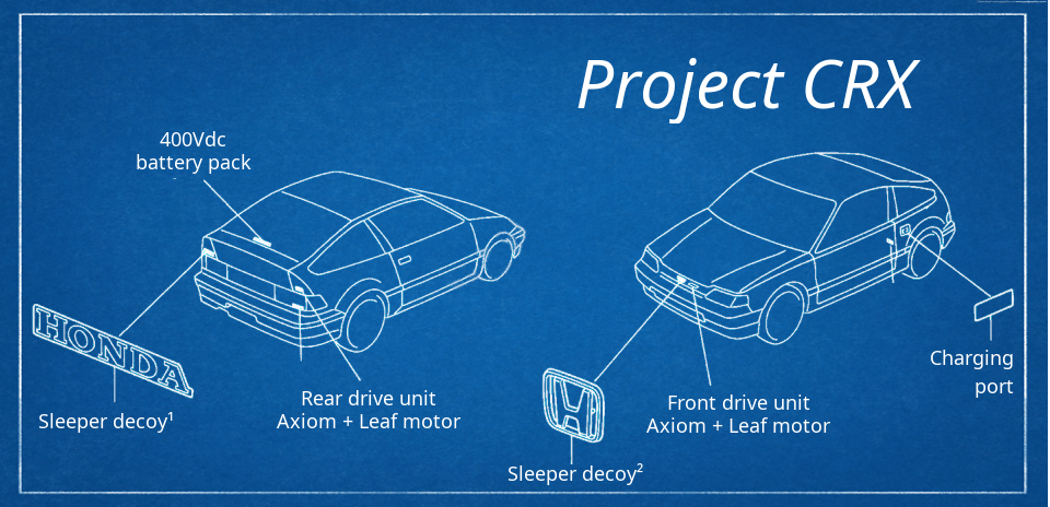
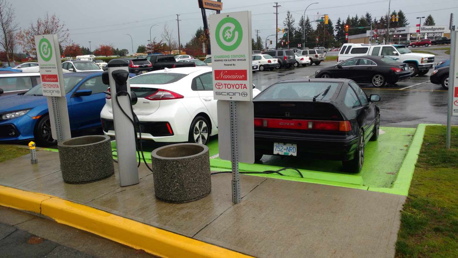
The marketing campaign will get shocking when we get to show the sheer power of Arlin's honda CRX powered by 2 Axioms and the list of customers test driving an Axiom in their own unique and interesting applications. We are hopeful to have the opportunity to learn from Supplyframe’s knowledgeable staff and industry contacts to help this marketing and advertising campaign make productive business to business connections.
-
New feature: GUI CANbus support
07/18/2019 at 22:19 • 0 commentsBecause we can have nice things
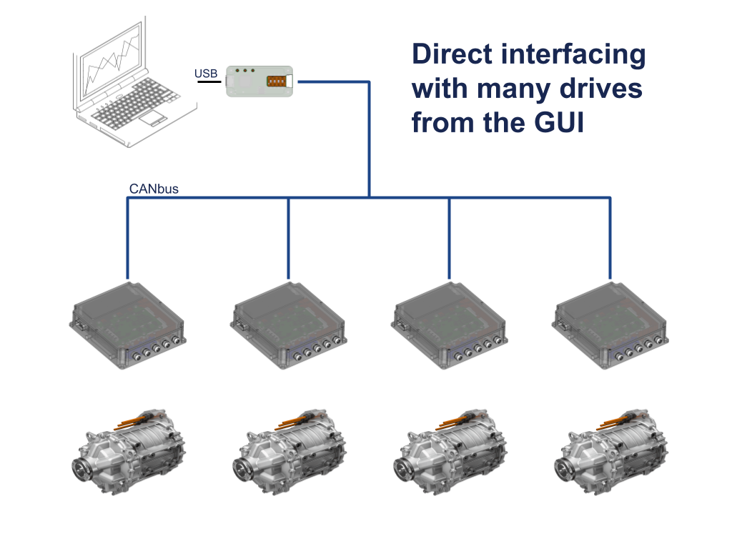
Consider your regular dayjob (or dayhobby) of using an Axiom-based controller. You are likely dealing with a silly amount of current, or voltage, or both, and you have to *work* with that while being safe. It is also likely that you need to work on more than one motor drive at a time, for example when you have an AWD dual motor honda CRX, or a one-motor-per-wheel setup with torque vectoring, or you are just stress testing 10 drive units in a test facility and you want them in a network.
In those cases, the good'n old USB interface of the vesc platform just doesn't cut it because a compromised isolation barrier in one controller will expose your computer to unsafe voltages.
For those cases we equipped every Axiom board with a couple of isolated CANbus interfaces: its the safest way to interface with a motor drive, providing a second isolation barrier with super low capacitive coupling for highest noise immunity.
And when you need to address several controllers, well, CANbus is the perfect protocol as it allows to send or receive commands from any node in the network. Within milliseconds you can send torque commands to 4 controllers in the bus.
![]()
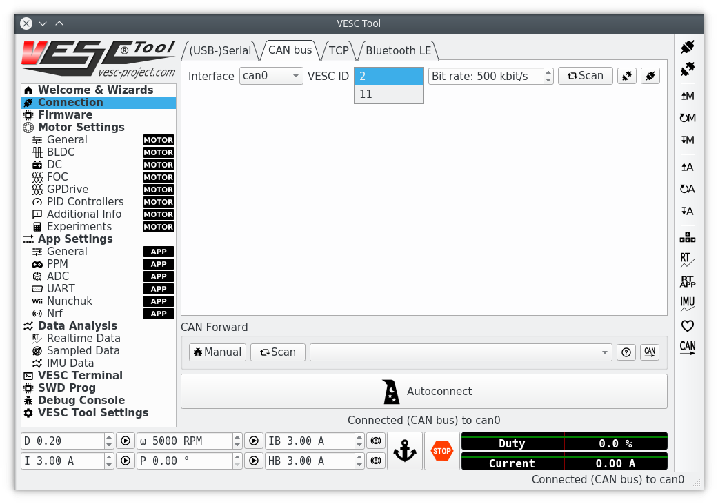
But there was a missing piece in the VESC platform: you couldn't directly connect to a CANbus with the VESC Tool GUI.
Until now!
Native CANbus support for VESC Tool
See here our Pull Request that adds native support for a can interface. You can discover all VESC's in the network, connect to one and perform firmware updates, realtime data acquisition, high speed sampling, motor detection, parameter config, etc, everything from the GUI.
![]()
This works nicely on linux. For windows support you may have to wait, code it, or hire someone to code it for you ;-)
It opens the door for proper instrument clusters
Something we want to address is data display. Whether its a sportsbike, a car, a plane or a jet boat (yes Axiom is already serving all those applications!) the human interface needs to be pretty, with Qt libraries we can do much better than a hacked gauge display
With VESC Tool codebase being capable of accessing the bus, it is now much easier to install a Beaglebone or a RPi in the vehicle with an industrial monitor and run a nice instrument cluster like this example from the internet that I compiled a couple of years ago on my old laptop.
Both VESC Tool and this example are based on Qt5 libraries. We hope to see some nice VESC displays in the future thanks to this
Update: we have a dashboard getting data from the controller:
In-house CANbus<->USB adapter
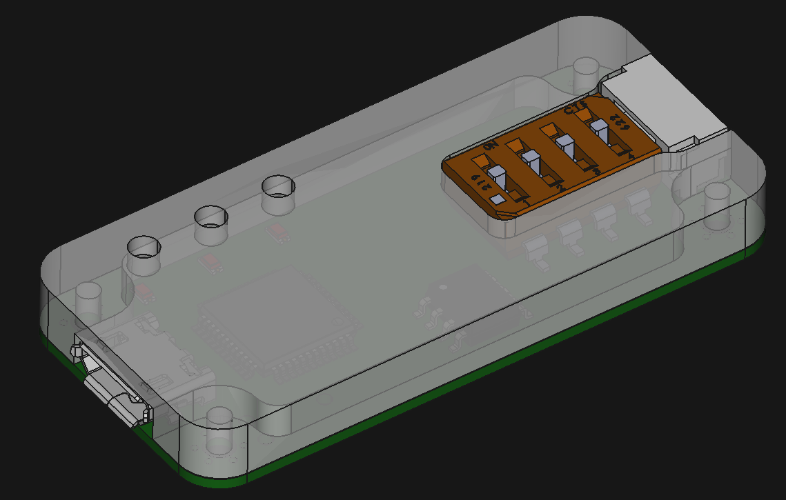
And here is the icing of the cake: every Axiom controller will come with a compatible CANbus<->USB adapter, using the open source candlelight firmware, and with perhaps the nicest build quality out there:
A few highligths:
- Aluminum shell. We machine it alongside the IGBT phase bars as they are of similar thickness
- UAVCAN compliant CANbus connector (SM04B-GHS). Its also the same used by Axiom
- Nicely embedded dipswitch to enable 5V bus supply, bus termination resistors and bootloader mode. This replaces the sloppy pin header jumpers.
- All the performance and features of candlelight firmware that now works out of the box with VESC Tool
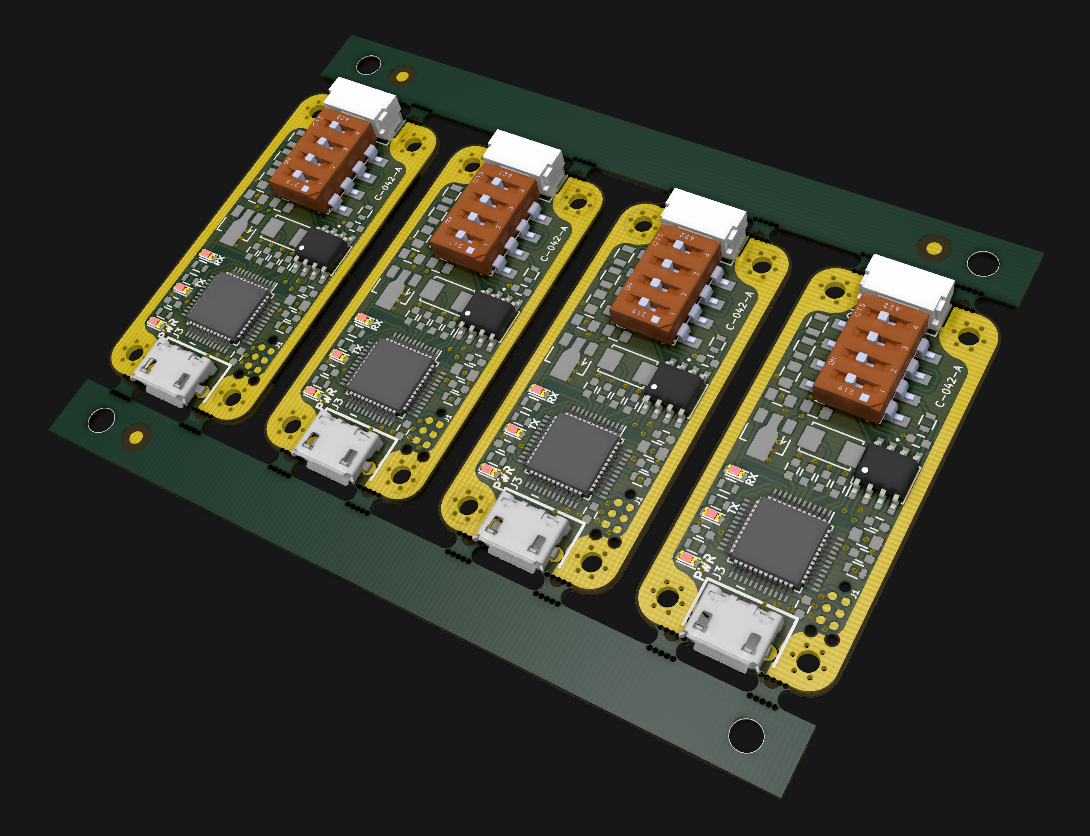
I ordered some boards to assemble in-house, if they turn out good we can send a batch for mfg. Being the coolest CAN<->USB converter out there it should sell well, not only to Axiom users.
Note that the boards are panelized, with tooling strips that provide fiducials and alignment holes for the stencil and production line. By panelizing myself I make sure the long edges will not be V-grooved, I want them routed for a smooth finish. Also note the proper contact between pcb GND and the aluminum shell for better shielding.
UPDATE: Working prototypes!![]()
![]()
As usual... stay tuned!
-
Deep Dive: "Shoot-through" Safety Feature
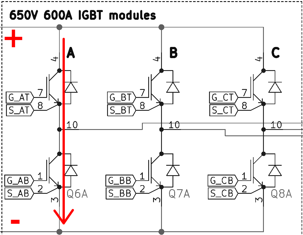
07/15/2019 at 02:50 • 0 comments“Shoot-through” is the name given to a failure event when two adjacent switches in a voltage source inverter are ON simultaneously thus short-circuiting the supply, as shown in Figure 1. This failure mode can easily become catastrophic especially in motor drive application where the DC link capacity is rather large and has more than enough stored energy to cause a fire if the shoot-through event is not extinguished within a very short time, typically 10µs for a rugged IGBT (other switch technology can be more sensitive and require even faster response times).
![]()
Figure 1: Shoot-through Event
It is interesting to note that the vast majority of the short-circuit current does not come from the traction battery back but rather the inverter’s DC link capacitor which has a very low impedance path between it and the power switches. This means that any current sensor between traction pack and the capacitor will not “see” the fault current and therefore cannot detect the fault. In fact, since there are no current sensors at all in the short-circuit path it makes detecting this type of fault challenging.
To detect a shoot-through event the gate driver (external to Axiom control board) employs a power switch “desaturation detection” circuit. The gate driver will immediately shut down the local IGBT when a desat fault is detected. When this first IGBT is shutdown the high fault current is extinguished before it becomes catastrophic and the Axiom control board will be notified so that its firmware can work to immediately shut down the other five switches, thus disabling the drive completely. Desaturation detection is a simple circuit, but its simplicity can often be mistaken for simple to design. The circuit must be 100% reliable in a high noise environment, be extremely fast acting and sufficiently stable over a very wide temperature range. Each component in a desaturation detection circuit is carefully considered and the PCB layout is similarly critically analyzed.
Now that the shoot-through event has been summarized, along with detection and shut down method, the next question is why would a shoot-through event even happen in the first place? Surely the control scheme is such that the processor would never issue ‘ON’ command simultaneously to two adjacent switches. No doubt this is the case.. but for unproven firmware, with well over 100,000 lines of code, its possible that a firmware bug may exist .. and its possible that such a bug could lead to errant command signals. More likely however is that noise from high voltage and high current switching gets coupled back into the control board causing unpredictable erratic behaviour, including causing a shoot-through.
Since the shoot-through event has the capability to be destructive it is well worth the designers time to invest an effort to prevent, however possible, the mis-firing of PWM signals. Axiom accomplishes this goal in several ways. The microcontroller firmware is based on proven code, used by thousands of users in a wide variety of applications. Despite this, Axiom makes use of an FPGA which monitors the IGBT gating commands to ensure, double ensure that the microcontroller does not issue errant PWM signals.
![]()
Figure 2: Overlap Protection Logic Circuit
The idea of this circuit is to allow the microcontroller to turn on its associated gate driver, either the top or the bottom, but never the top and the bottom simultaneously (shoot-through!).
The logic truth table is deciphered as:
![]()
Figure 3: Overlap Protection Logic Circuit Truth Table
In earlier revisions of Axiom the PWM overlap protection circuit really was implemented like this using discrete hardware. More recently the simplistic logic diagram is implemented in an FPGA (see previous log HERE)
Once the PWM has been checked by the overlap protection logic, it heads off to the Gate Driver board whose job is to turn digital PWM into a power pulsed equivalent to drive the IGBT. The Gate Driver board sits right at the interface between noise high power IGBT and sensitive digital and therefore becomes the most critical component to overall function. Members of EV Power Designs have been designing Gate Driver boards for high performance application for over 15 years, a version of which went into a World Record Breaking race down the 1/4 mile track. Hard experience has taught that a rock solid, highly fault tolerant, excellent common-mode rejection capability, desaturation detection, two-step turn OFF and other built in features are required for high power high performance motor drive application. Besides our own custom design which have these features, EV Power Designs also recommends gate drivers by Power Integrations (formally IGBT-Concepts).
With digital voltage on one side, high switching voltage on the other and a dielectric in between (plastic case of the opto-isolator) suddenly you have an effective capacitor injecting noise current through it (from switching high voltage gate driver to digital, noise current crawling over the plastic case. For lower power applications this is practically a non-issue, but high power its a real concern. Not all opto-coupler, gate drive IC’s or PCB layouts are up to the challenge. This concept, also applies to the gate driver power supply, specifically the transformer. Noise can travel through the parasitic capacitance here too, so less than 5pF input-to-output capacitance is desired.
Is the story done? There’s still one more major failure mode to be considered. It was previously mentioned the shoot-through current is extremely high and lasts only a short period of time (desat protection opens the circuit in less than 10µs), but that time is enough to charge the stray inductance of the fault current path shown in Figure 1. This could be represented schematically by placing the inductor symbol for the DC link capacitor (internal inductance + connection to IGBT) and the internal inductance + connection of the IGBT itself.. both of them, like so:
![]()
Figure 4: Stray Inductance in Shoot-through Path
The high current flows through the stray inductance(es) and then the desat protection circuit opens one of the switches to protect the system. As is well known to Electrical Engineers, the current in an inductor wants to continue to flow and when an inductor is suddenly open circuited, a voltage will spike to very high values in an attempt to keep the current flowing. At the power levels typical to Axiom, the stored energy is significant and the voltage spike can be destructive. The irony of the situation, the desat protection circuit worked but it caused another problem! Therefore the system has to be designed to mitigate this potential hazard as well. EV Power Designs has three solutions to contain the voltage spike within tolerable limits. Firstly, the Axiom control board was intentionally designed to mount directly to a gate driver from Power Integration (formally IGBT-Concepts) which was specifically chosen for its rugged construction and reliable fault management and that direct mounts on a very stray low inductance IGBT from Infineon. Secondly, EV Power Designs contracted a capacitor manufacturer to specially design a DC Link capacitor with very low internal self inductance. Thirdly, the proposed connection between DC link capacitor and IGBT switch is maintained at absolute minimal length with no need for external copper busing or snubber capacitor.
![]()
Figure 5: Full Up Controller Designed and Assembled for Minimal Stray Inductance
Multiple levels of protection have been designed into the motor drive full up controller to properly manage the threat of a shoot-through, or the voltage spike which occurs after a shoot-through event.
Deep Dive over, lets resurface shall we?
-
Episode IV: A New Hope
07/06/2019 at 16:02 • 0 commentsArlin is giving a new life to his 88's Honda CRX
It may be not a DeLorean or a TIE fighter, but it sure will be a memorable craft.
So this is how a new EV conversion begins:
With a donor car!
![]()
The plan is to install an electric drivetrain on the front wheels and another one on the rear wheels, if all goes right it will become our monster flagship, the perfect marketing recipe to spread our work around the globe.
(images from the owner's manual).
The used car was a good deal and the motors are really cheap as they came from damaged cars, the real challenge is to afford some good batteries capable of delivering this kind of power.
Conversion work started last week, on Arlin's own car.
There have been prior Episodes to the CRX saga that you are missing, you can find them digging in endless-sphere forums ;-)
Arlin was recently interviewed to let people know where he is at, and here are a couple of lines from the interview:
Why did you choose a Honda CRX for your conversion project?
A few reasons.
- It’s light weight
- Low coefficient of drag
- Honda’s are easy to work on
- Cost
How long or how many hours were put into the build, from removing the first internal combustion engine (ICE) component to driving with battery power?
The mechanical conversion portion for the FWD was about 80 hours of work. But the development and tuning of the custom 3 phase motor controller was 10s of thousands of hours of work. People really don’t understand how hard it is to develop the motor controller. It’s like 2x as hard as the battery and 5x as hard as any other part on the car!
For more insights, head to the complete article:
http://electricss.com/qa-converted-honda-crx/
This is his second CRX build, his original record CRX is currently decommissioned, but if in the future you run into a 80's honda charging electrons, chances are you're looking at an all-out earth-shattering monster.
![]()
That old CRX wasn't running a VESC-based controller but a Lebowski-based one and it pulled more than 300hp out of that drivetrain using mostly donated or handcrafted parts. Everything learned form that car is being applied to our Axiom motor drive:
If you like what we do, any kind of help is super useful to get the car done. Parts, used motors, batteries, IGBTs, cables, experience, everything helps as this is really pushing the limits of a small team with a limited budget.
Busy times for our mechanic-in-chief!
-
Mechanicals, part 1
07/01/2019 at 16:19 • 0 commentsAssembly basics
For several months we got the electrical assembly figured out, and its good and simple for evaluation (Imagine a company looking forward to introduce this controller into its production line).
This greatly reduces the assembly time, and its literally a bolt-on solution to these high power IGBT modules.
The point of this basic, enclosure-less assembly is to let customers test this system on their dynos, with their motors. Its purposely open framed for easy access to testpoints, coax connectors and LEDs; it must be easy to work with.
This same concept is helpful for one-off builds, as those will likely require some debugging and double checking of everything.
Fully enclosed version
As cool as it is, its certainly not enough to convince a big customer, they need a few basic items to take Axiom seriously:
- An enclosure, and most important the assurance we can customize it to their mechanical requirements
- IP67+ ratings
- Marketing material
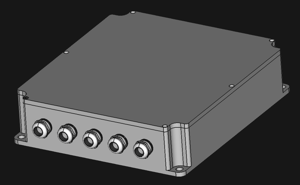
Enclosure design
We chose to make a fully parametric enclosure design, in order to easily make changes to support different mounting arrangements. Due to EMI and IP ratings the material is most likely aluminum, and since upfront tooling costs of a CNC job are way lower than plastic injection or die cast, its not unreasonable for a customer to spawn a new design. For a large production, aluminum die cast is an option, but you really need volume to make it the lowest cost option (thanks Eric for this tip at the mentorship session).
The design is of course made in FreeCAD, a multiplatform, open source, no hassle and powerful MCAD tool. It also has a particularly good integration with KiCad.
We had some requirements for the enclosure:
- IP67 (actually aiming for IP6K9K) with off the shelf o-rings
- Full shielding for easier EMC compliance
- Integrated liquid cooling
- Experience told us that High Voltage connections must be on the same side
- Easy service
- Compact
- Nice looking for marketing
To get the enclosure looking like this, we made custom busbars for the phase outputs, a custom laminated dc busbar to reach the DC link with minimal EMI inside the enclosure, proper sizing for the coolant ports and keeping in mind this has to be machined in a 3 axis CNC, so there is some design for manufacture going on here like minimizing the milling surfaces to 4 (top surface, bottom surface, HV connectors side, los voltage signal side).
Integrated liquid cooling would be a major cost saver here, as the coldplate we currently list in the BOM costs around $300, we could have the whole enclosure made for that money. Its also an awesome place to spend Axiom's award of $500 for finishing first in the Hackaday Prize Bootstrap stage.
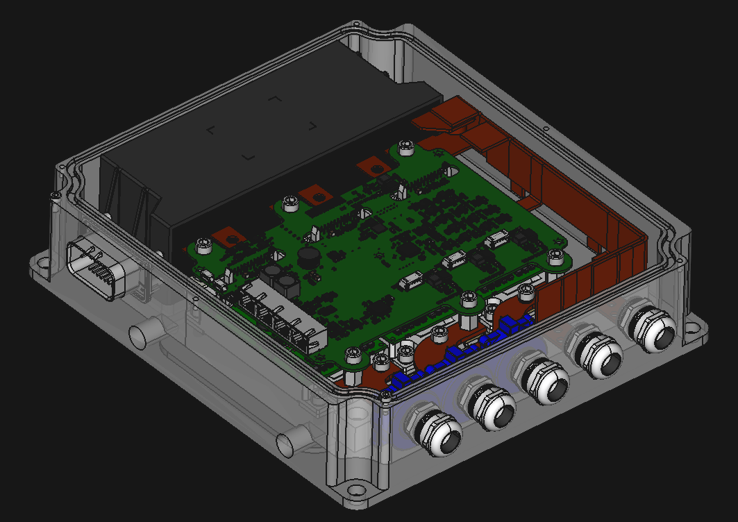
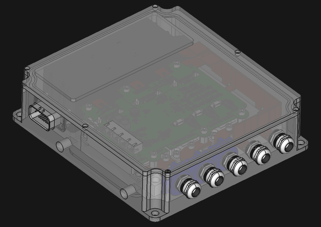
Lid off! showing some internals:
Have you heard about semi-transparent aluminum? Me neither, this is just a CAD transparency setting.
Going for a tidy and minimalist design:
The mechanical design is not ready, "Mechanical, part 2" will be about the design of the enclosure belly, which is responsible of the cooling performance of the motor drive because it includes the coolant channels and pin fin design below the IGBTs, which requires optimization of pressure drop vs thermal flow from IGBT to the coolant. If anyone knows how to do this FEA in FreeCAD, it would be most welcomed!
Its really cool that fully open source tools like KiCAD and FreeCAD get you this far into product development.
The great news is that we are arriving to the final exterior look and feel, that means we unlocked a major road block for marketing development!
-
Powerstage validation
06/20/2019 at 20:27 • 4 commentsDouble pulse testing
Here is some test results we had a while ago when doing double pulse tests to validate the powerstage and our custom DC Link. You can't skip this if you are making a motor controller.
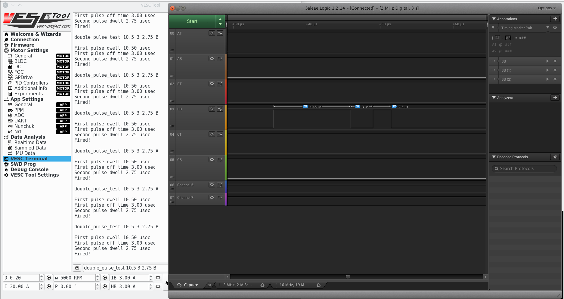
First of all, we coded some handy functions and commands to perform a double pulse test from the VESC Tool GUI.![]()
This way from the command line I can easily and accurately set the timing with the controller fully assembled. Otherwise you would need a signal generator, remove the control board, prepare the wiring to the gates, and change the wiring to test each of the 6 switches.
A test setup is something like this:![Image]()
You want to observe the switching characteristics of the drive at peak current load. To do that you keep the top IGBT in OFF state (Our powerstage will keep the top gate at -9Vdc)
* Turn ON the bottom switch and let the current through the inductor increase to the desired test current (dwell time).
* Turn OFF the switch and observe the voltage overshoot
* Wait a minimum amount of time and turn ON the switch (rated current is still flowing through the body diode of the TOP switch)
We have some handy support math to calculate the construction of the inductor, the required inductance and time required to reach a set current.
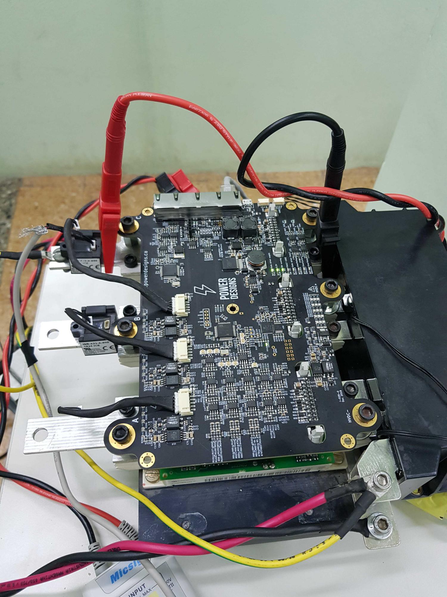
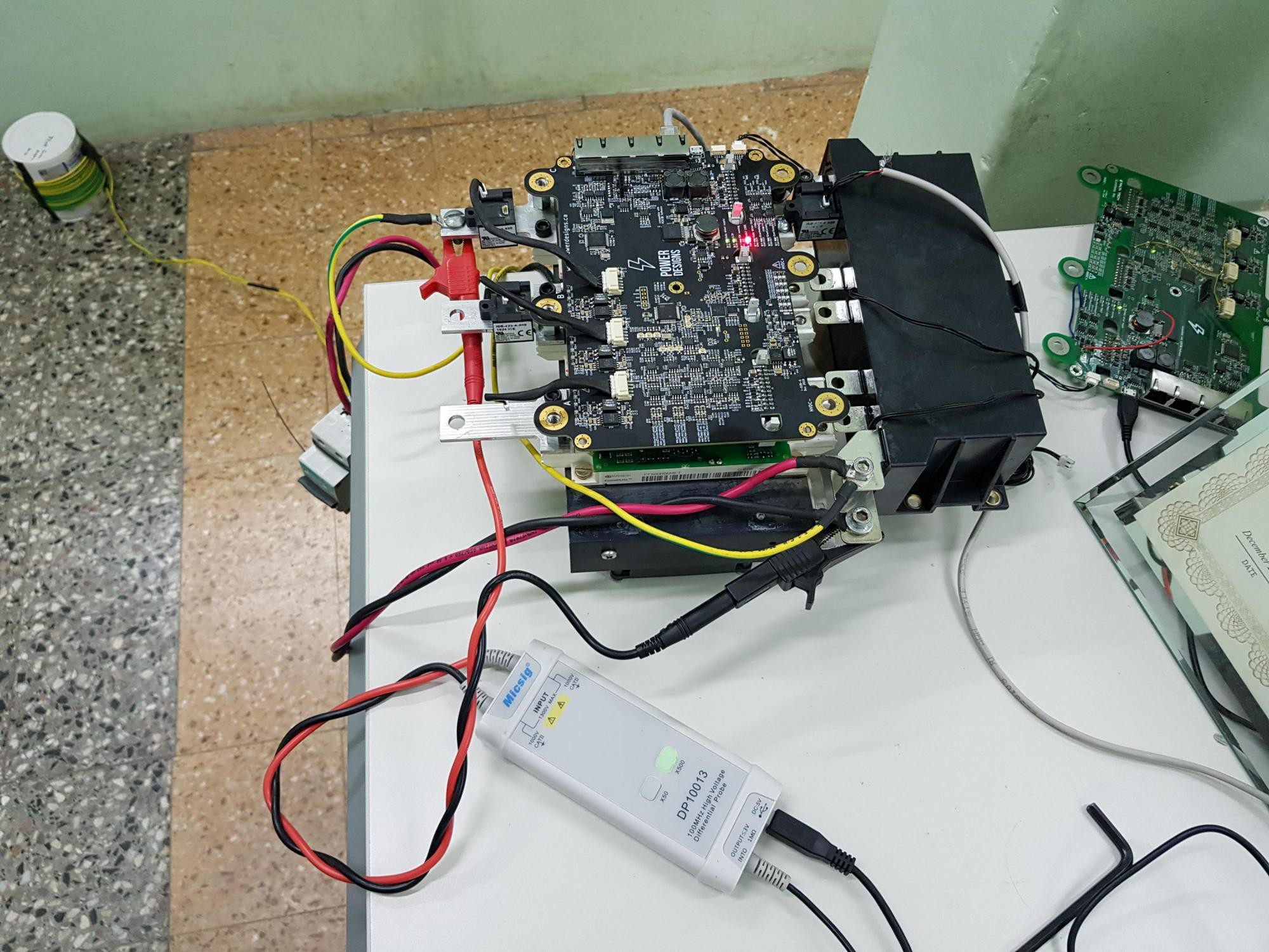
A test bench looks something like this:![]()
Note that voltages are measured with differential probes to avoid damaging the oscilloscope, and measurement happens directly at the IGBT terminals
![]()
On the top left you can see the inductor for the test. We communicate to Axiom through the isolated CANbus interface so the laptop is isolated from the device under test.
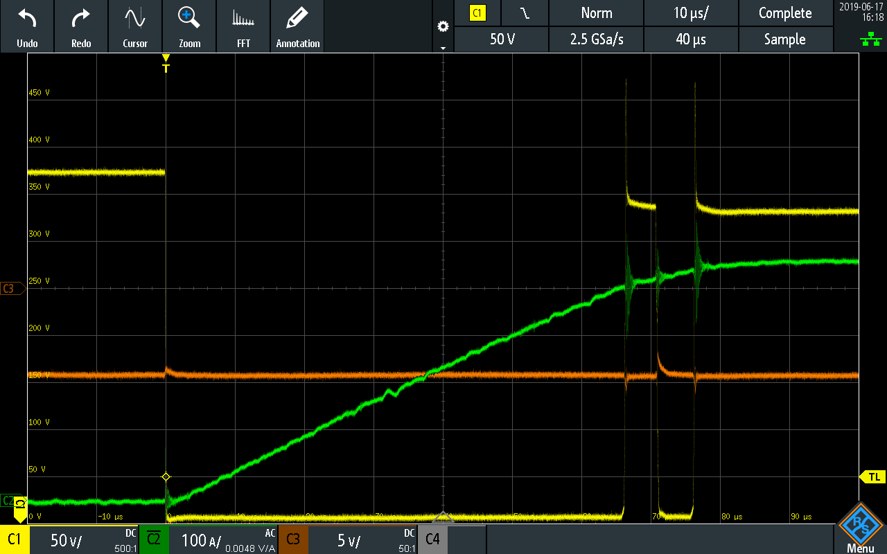
Double pulse test result at 375V 450A:![]()
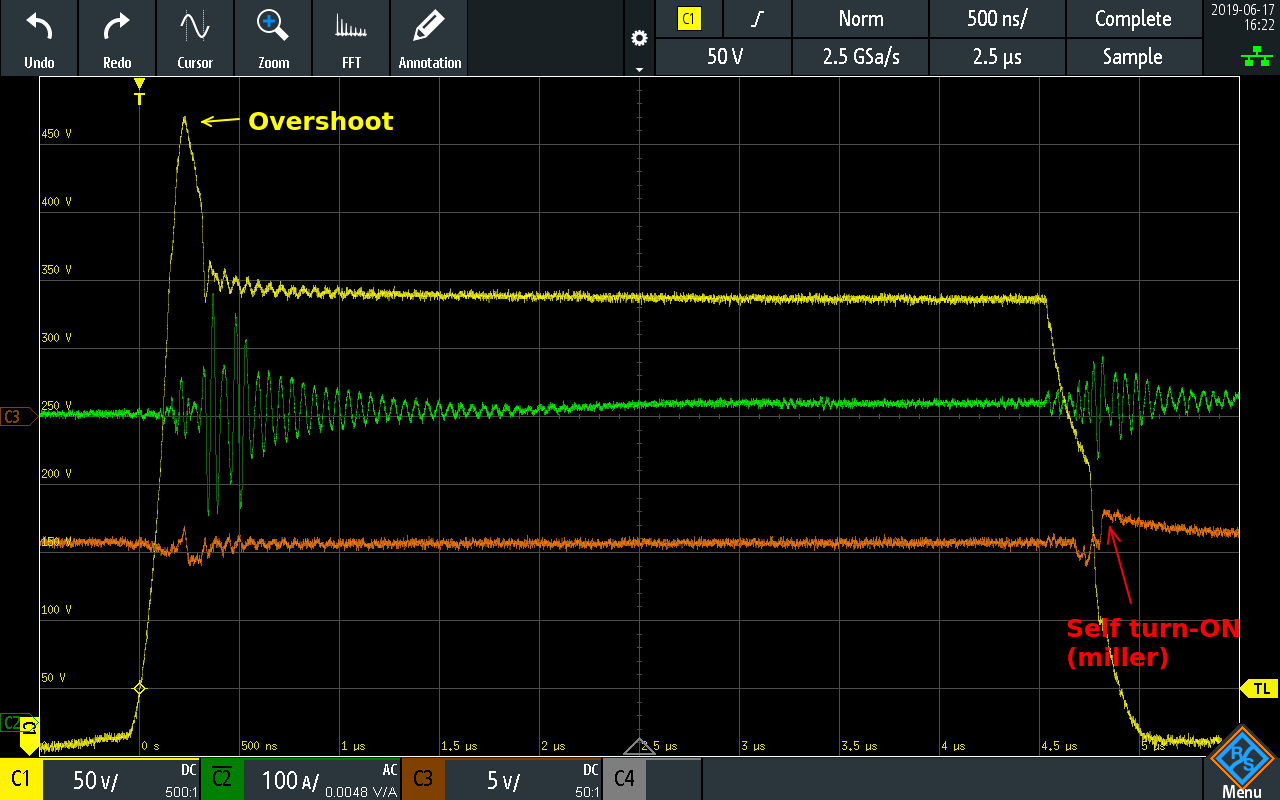
And zoomed in:![]()
Yellow trace is Collector voltage (to measure overshoot), green trace is phase current, orange trace is TOP IGBT gate (to observe miller effect).
The overshoot is caused by the inductance of the path between the silicon switch and the DC Link capacitor. This includes the internal IGBT module wiring, the connection to the DC Link and the internal DC Link ESL. We tested other DC Link and ours performed better during this testing. Overshoot can change wildly if your DC Link is not carefully designed; we have a 100V overshoot, imagine how bad can it become if the DC Link ESL is left unchecked.
Overshoot must stay below the IGBT rated voltage, which is 650Vdc minus some buffer %. If we were operating at higher DC bus voltages we can either test snubbers, slow down the turn OFF time or just use a 1200V rated IGBT.
Miller capacitance between gate and collector of the TOP switch will try to turn ON that switch when its supposed to be off. We check that the gate sits at -9Vdc and miller can only pull it up to -7Vdc, thats good. You get a shoot through + fire if Miller is able to turn ON the TOP switch.
Something really good about double pulse test is that you can measure the switching losses, and we have access to a very good rogowski current probe but its only capable of measuring 300A and we are more interested into the 500A to 800A range. We did measure emitter current but the sensor can't properly track the slewrate. Maybe next time.
Double pulse testing is something *every* controller design should have endured, you don't know how the powerstage works until you observe it. -
Let's talk about the FPGA...
06/14/2019 at 11:29 • 2 commentsIn the early days...
Axiom originally started with discrete logic that was in charge of 2 specific tasks:
- Shoot-through elimination
- Fault latching
Avoiding shoot-through
A shoot through happens when both TOP and BOTTOM switches in a leg turn ON at the same time, creating a dead short across the 400Vdc input.
If that would happen and no protections were in place, your vehicle would become a ball of fire. We want to make sure a '1' is never commanded on both top and bottom switches at the same time, even in case of a firmware bug or microcontroller damage.
This was our hard solution to a hard problem:
Input pulldowns make sure the signals stay in '0' while the microcontroller is under reset and during GPIO initialization. If you follow the logic, it will set both top and bottom to '0' when both inputs are '1'.
This takes 3 logic ICs (U5, U6 and U7) plus bypass capacitors, but it had the extra benefit of level shifting the signals from 3.3V to 5V for higher noise immunity.
Latching faults
When a fault happens, we don't want to rely on the firmware to keep things safe. In this context a fault can mean 2000+ Amps flowing close to the microcontroller with very high, and possibly damaging levels of EMI.
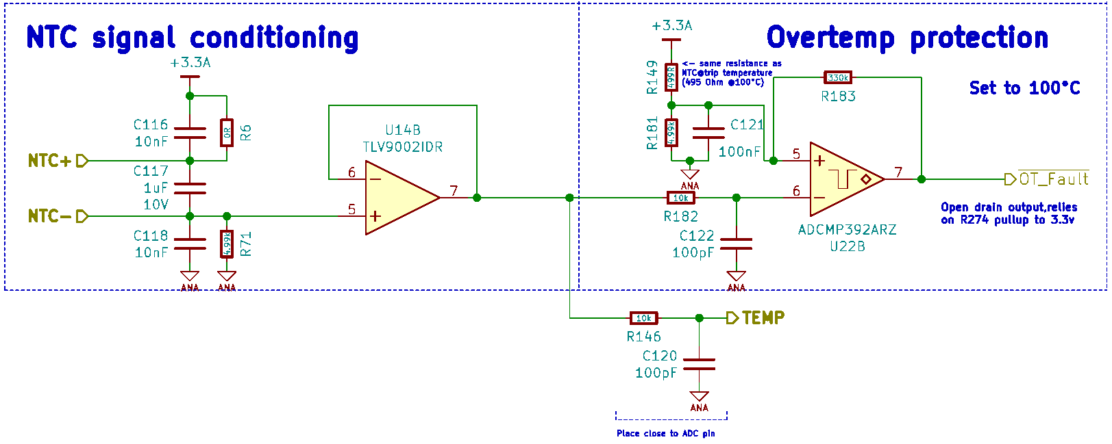
With that in mind, our analog signal chain has comparators that will trip a fault when a voltage, current or temperature signal goes beyond design limits, like this example: (Temperature signal path is simpler than voltage and current)
The problem here is that the comparator will only assert a fault while the fault is present and then return to the normal state. With the temperature it can be a few seconds, but in case of voltage and current, those are likely microseconds and we can't afford to miss that signal.
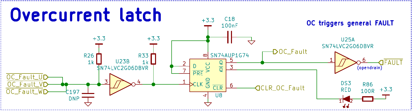
Enter discrete fault latching:
This bit of schematic was taken from an ancient forum post of our power electronics guru, it latches a fault until the CLR_OC_Fault is cleared, and we had a latch circuit for current and another for voltage because we need to know why it faulted in the first place. We leaved overtemperature unlatched because it was quite a lot of parts, this discrete solution already takes 7 ICs.
Let's talk about the FPGA...
Despite there are many FPGA manufacturers out there, there is one that is special.
They all require you to install gigabytes worth of software just to create the simplest logic, but in case of the ice40 family, there is a interesting open source effort to reverse engineer their logic and create an open source toolchain, just like gcc, but for FPGA's. Its called Project Icestorm.
And now that we have a backend, 2 other projects emerged to make it more user friendly:
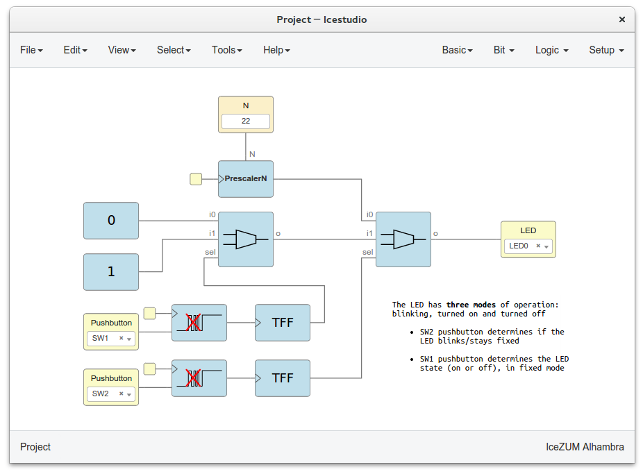
Icestudio allows you to easily draw your logic circuit, like their example from their frontpage:
Yes, its that easy and the whole software package only takes a few megabytes! And it won't bother you with licenses, activation, sign ups, ads, newsletters.
I chose the ice40up5k, its not automotive grade but its low cost, and at 5k logic cells it has potential to fit some promising logic. I ran the awesome risc-v core in our Axiom board and developed delta sigma demodulation on this fpga, its good stuff.
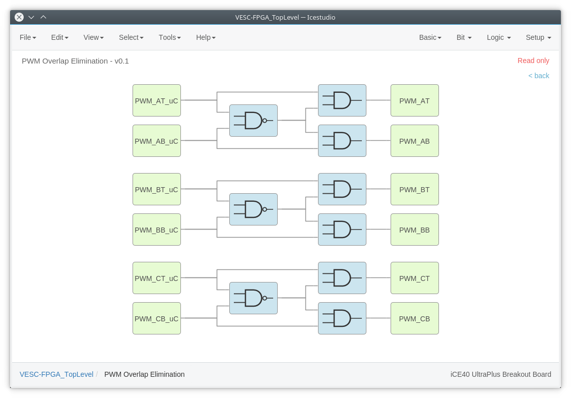
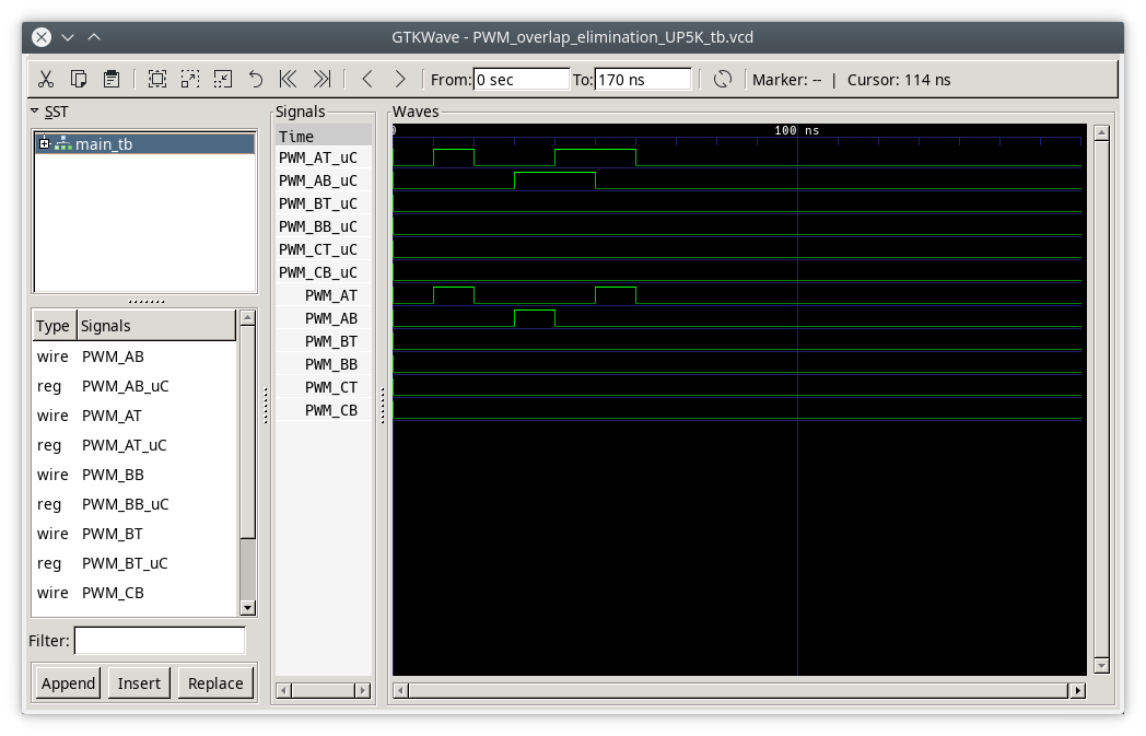
Shoot through elimination, FPGA-style
Remember the discrete implementation? Axiom board recreates that hardware inside the FPGA
And we can easily simulate the behavior by just typing "apio sim", icestudio creates a testbench template for you.
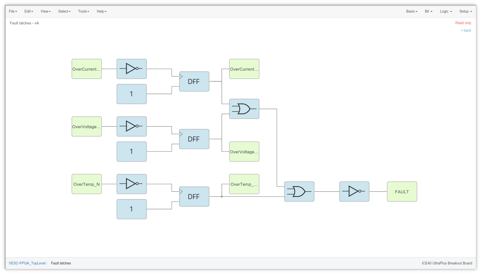
Latching!
In a similar way, we can implement a latch circuit like this
![]()
Note that now we do have a temperature fault latch, this time for free.
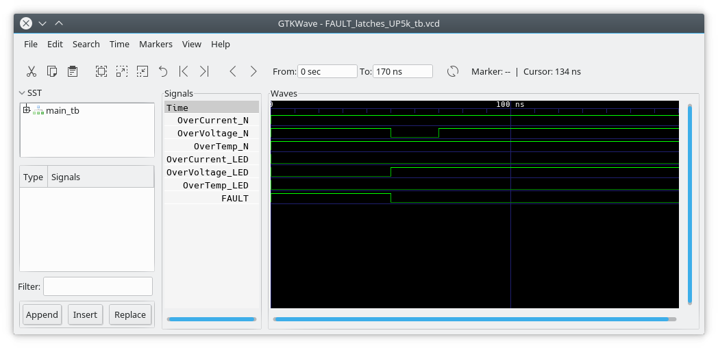
With apio we can again simulate the behavior of the block:
![]()
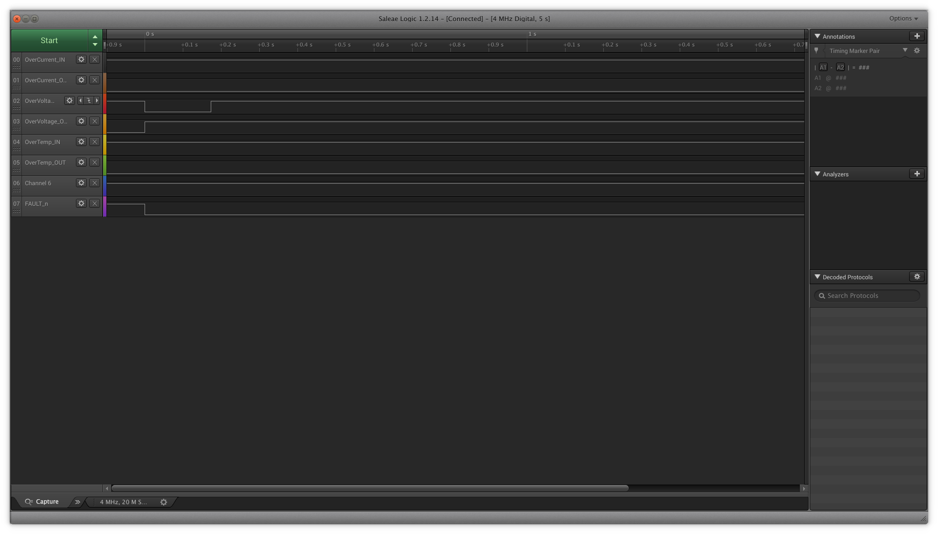
And because I have the ice40up5k evaluation board, I can actually measure the signals in the hardware using a logic analyzer for validation.
![]()
I hope this shows how easy and promising it is to develop on an FPGA nowdays, especially for the simple stuff.
As Axiom FPGA code grew in features we left behind the pretty icestudio and we now run a full featured verilog HDL project because a GUI makes simple tasks simple, but complex tasks impossible.
We can make the FPGA to work as an external watchdog, a coprocessor, accelerator, deadtime monitor or whatever we need, its really valuable for a research team to have all this integrated and ready to go, and its placed in just the right spot where all the critical control data flows:
The FPGA configuration is stored in the MCU flash memory and can be updated from the GUI, and is key to protect any special IP we develop in-house.
Verilog allows Axiom to go way beyond replacing a few logic ICs, it can make obsolete the whole analog signal chain by demodulating and sinc-filtering a delta sigma stream, in all 7 analog input channels, which is unheard in motor control industry. We'll get there someday, it just needs software, hardware is ready!
-
Highest power VESC bike?
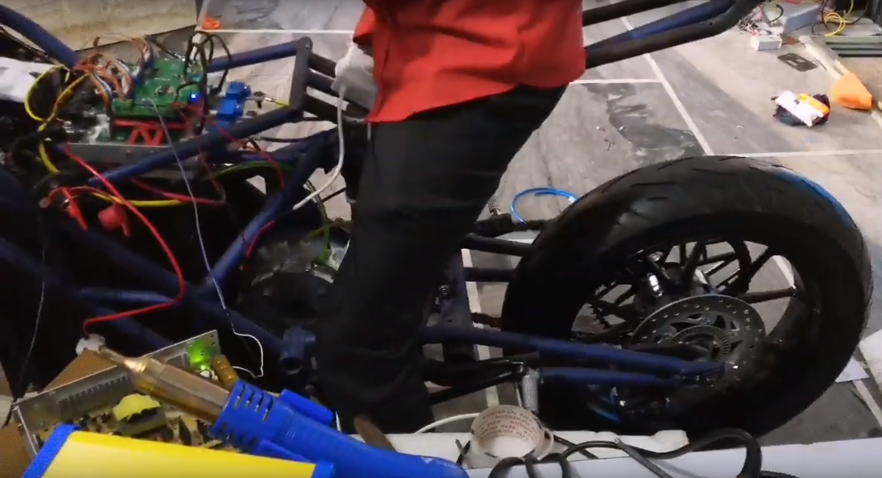
06/13/2019 at 22:30 • 2 commentsLaying rubber at 700Amps
Meet Hackey's team using an early version of Axiom to have some fun! As much as we love emissions-free vehicles, this ain't one, but its certainly the hackiest build out there!
Now lets do a quick recap:
As you may notice in the video, they built an old version of Axiom, the one we released here. Main differences with the latest and greatest revision competing for the Hackaday Prize are these:
- Discrete fault protection logic was upgraded to an FPGA (with an open source toolchain!)
- Improved voltage sensing
- Greatly improved packaging, wiring and ease of assembly
- More safety features
They use the same 650V 600A Infineon EconoDual modules we showcase in our project description. If you take a look at the datasheet they are rated for continuous 600Amps DC (no switching!) at 60°C, and 700Adc at 25°C.
The user interface of most FOC controllers sets peak current. So when you set 700A, its actually 700Apk, (496Arms). Its crazy current, but still manageable for short periods.
A fun thing to note is that they are using only a 70V battery and getting 52kW of power, but their IGBTs are perfectly capable of going all the way up to 400Vdc, so it could be way past 200kW! Yes, thats 270hp!
In a bike!
Granted, a very special battery would be required, safety and turn-off overshoot needs to be carefully handled (a cool log about this critical part will be posted soon).
Powerstage:
![Image]() Liquid cooling!
Liquid cooling!![Image]() I actually don't know how that coldplate was made, pretty sure it wasn't CNC machined.
I actually don't know how that coldplate was made, pretty sure it wasn't CNC machined.This isn't the highest power Axiom out there, but its a cool one that sorted out a ton of challenges on a very short budget. Its also one of the few not under an NDA!
We are hoping to see them tidying up the wiring and securing down everything to make it safer, and its cool to see that the design still works even with long wiring and the old 2-board approach.
Axiom is literally empowering people from all around the world to achieve a 100kW-class motor drives, because we need and we want electric vehicles around us.
Stay tuned!
Axiom: 100+kW Motor Controller
High Power, High Performance 400V 300A 100+kW Motor Controller fully compatible with VESC®

 If that would happen and no protections were in place, your vehicle would become a ball of fire. We want to make sure a '1' is never commanded on both top and bottom switches at the same time, even in case of a firmware bug or microcontroller damage.
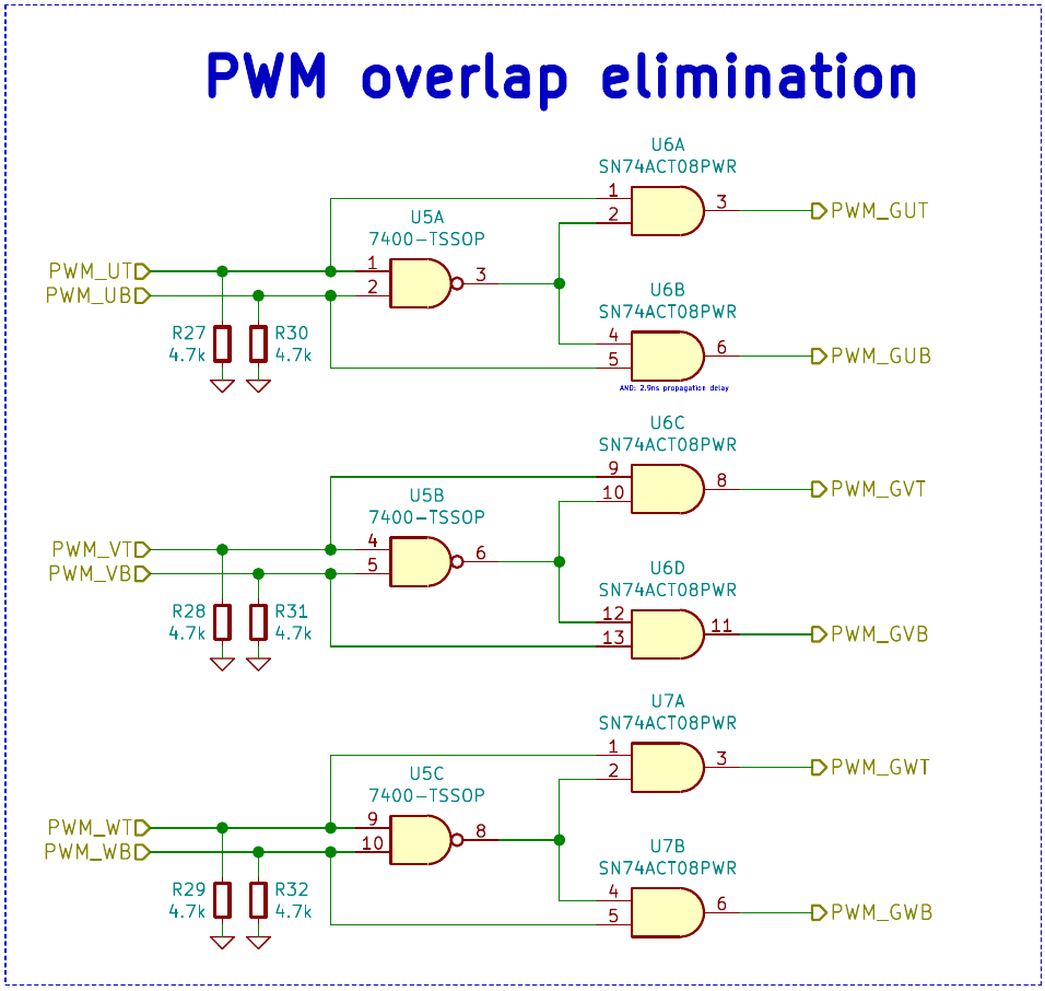
 Liquid cooling!
 I actually don't know how that coldplate was made, pretty sure it wasn't CNC machined.