Marcos
-
Waterproofing
06/05/2019 at 23:36 • 1 commentGoing for IP67
Something I learned through the path of enclosure design after our last mentor session with Eric Weinhoffer, is the nitty gritty of enclosure sealing.
So our target customer needs a water resistant motor drive, and to be on the safe side we will spec it for IP67 or better (requires testing at 1 meter deep for 30 minutes). If your case is a single piece with no connectors, easy peasy. If you have signal connectors you need IP67 rated connectors. That's okay, we can get those easily from digikey.
600Amp connectors? Well those are harder to find but industry usually seals the thick conductors with cable glandes, so we'll go that way.
Hum, last step is sealing 2 perfectly flat surfaces. Sounds easier than it is, you need a rubbery compressible material between those surfaces, we all know that. What I didn't know, despite I've been a mechanically oriented EE is how clear the rules are and how deep the knowledge is about seals.I've seen plenty of custom made gaskets for electronics enclosures, but after a light reading it was evident that the easier and cheaper way to seal is using off the shelf o-rings.
Enter Parker, the age old o-ring industry leader, with an old and extensive handbook that has perdured for decades instructing us engineers to design proper sealing into our products.Step 1: Read The Fantastic Manual
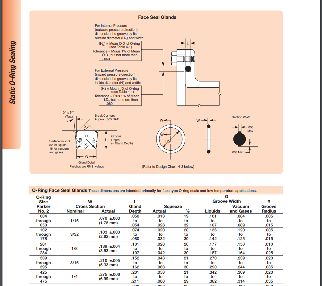
The Parker O-Ring Handbook is a 50 year old piece of literature that surprisingly hasn't changed that much over the decades. Its on the boring side for an electrical engineer, until you get to the practical design charts:
![]()
Step 2: Determine O-Ring diameter
So if we are going for an enclosure that needs to prevent liquids on the outside from entering, your O-Ring inner diameter needs to be the same length as the inside diameter (if the groove were circular.
In a sort of rectangular enclosure, we need to know the line selected in green here:
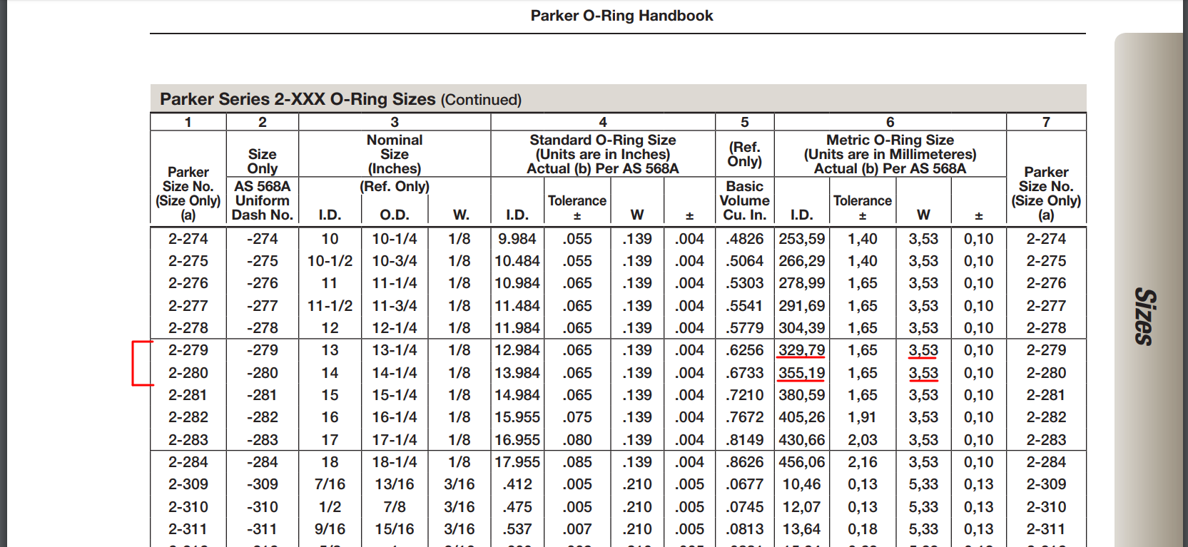
In reality, you will roughly estimate the required O-Ring diameter based on that green line length and it will obviously won't match the off the shelf o-rings, but now you have a ballpark that lets you know which o-ring cross section you will use.
In our case (oh the pun) I could narrow it down to part# 2-279 or 2-280. They only differ in the Inner Diameter (329mm and 355mm). Now the groove needs to modified so it either measures 329 or 355mm to match one of those o-rings. Our enclosure initially had 340mm, so either we make it smaller or larger to get a match.
Step 3: Groove profile
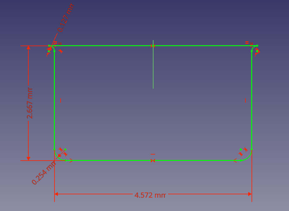
Given a 2-279 O-ring, we know its cross section, that's all we need to know to design the groove, if you work with the free and awesome FreeCAD and followed the first image, it will look like this:
![]()
The fillets on the top are required to avoid pinching and damaging the O-ring, and the draft angle would be 0° if you are CNC'ing your enclosure or up to 5° if you are diecasting. Depth and width are given by the tables.
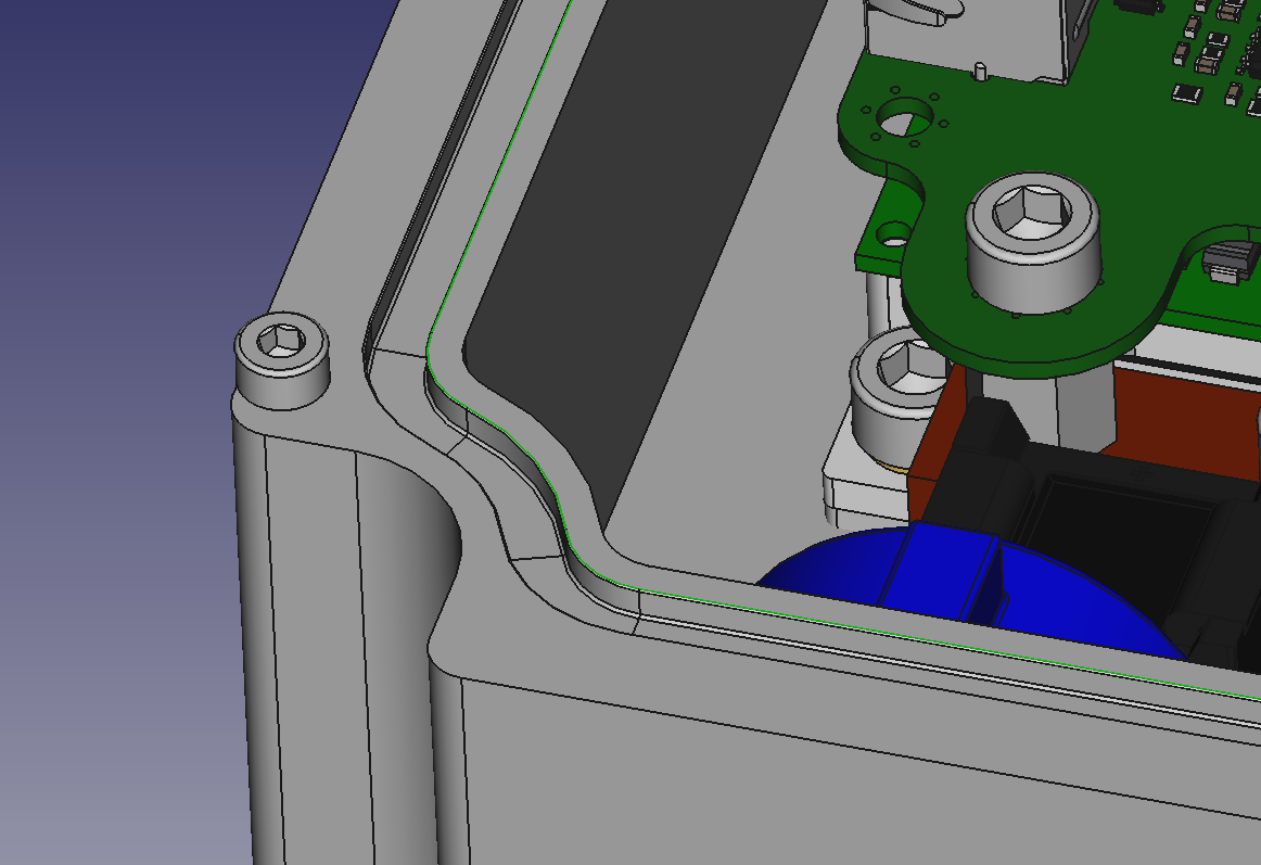
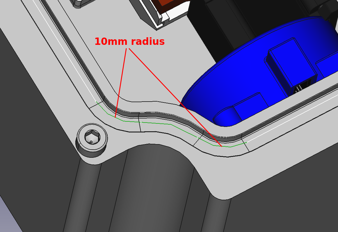
Step 4: Check radiuses
In the second image you can see there is some wiggling in the groove, that's an old trick to increase the available volume inside the enclosure. You can do it on the corners or to surround a bolt, which makes for thinner, lighter and less massive enclosures.
But here's the catch: according to the handbook, you can't bend an O-ring with a radius sharper than 3 cross section widths. In our case that would be a 10mm radius, less than that would compromise the sealing. Ideally you want to use x6 widths.
This means that if you want your O-ring to closely surround your enclosure bolts, you are probably going fail the radius check and inevitably fall into a custom made sealing gasket. That was a wow moment, when I realized the exact limit between using an easy off the shelf O-ring and a ton of hours spent into the design and supply chain of a custom gasket.
Axiom enclosure is not done yet, but this was cool bit of product design that I thought its worth sharing.
-
Axiom Workshop!!
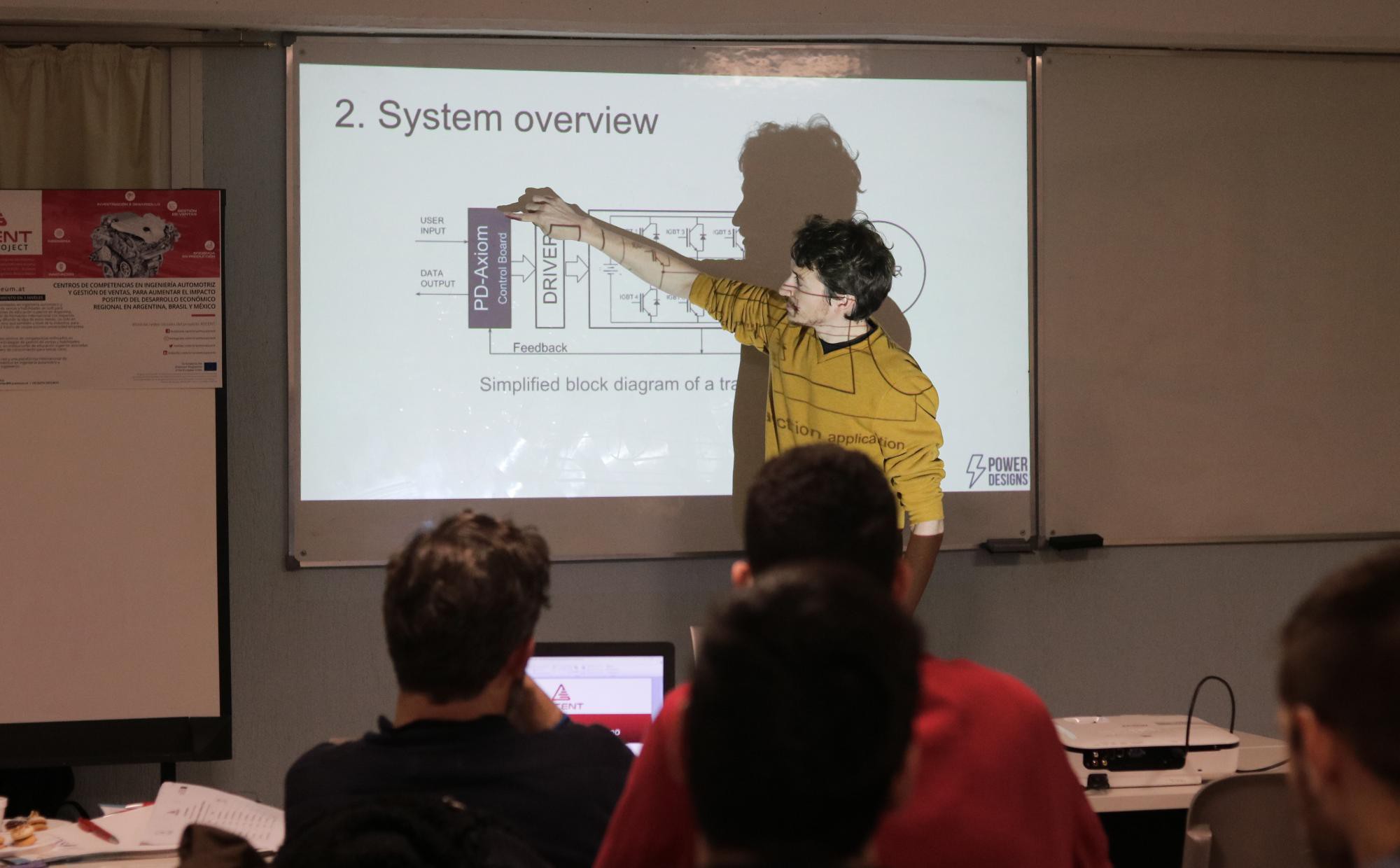
05/31/2019 at 11:19 • 0 commentsFirst Axiom workshop!
Last Thursday we had the chance to present our work in the 2nd Automotive Engineering Workshop hosted at the Department of Electrical Engineering (DIEC) of the UNS University in Bahia Blanca.
![]()
Attendees took a glance at the current state of the art of Engine Control Units, the progress towards electric vehicles, and were presented with a crash course about Axiom. They learnt the building blocks, features and capabilities of our motor drive, followed by a demo of Axiom running a motor control simulation. They could watch all the math unfold into nice current, voltage and phase plots emerging from the motor model, an awesome tool for research.
The DIEC research lab has plenty of high quality Rogowski probes, big dollar scopes, 600V power supplies and some cool SiC modules. We should visit them more often!
Fun times!
-
Check out Axiom Datasheet!
05/16/2019 at 02:32 • 0 commentsWe are ready to release the Axiom datasheet!
Next Monday all our subscribers will have access to the datasheet through our newsletter.
To subscribe to the newsletter, sign up here!http://www.powerdesigns.ca/newsletter/
It will be only available to the subscribers for quite a while until we let the file publicly available for download.
Important announcements will happen there as well, so we hope to see you guys in the list!Woot, datasheet released: http://www.powerdesigns.ca/files/Datasheet-Axiom-control-board.pdf
Cheers!
-
Design For Manufacture - Board Level
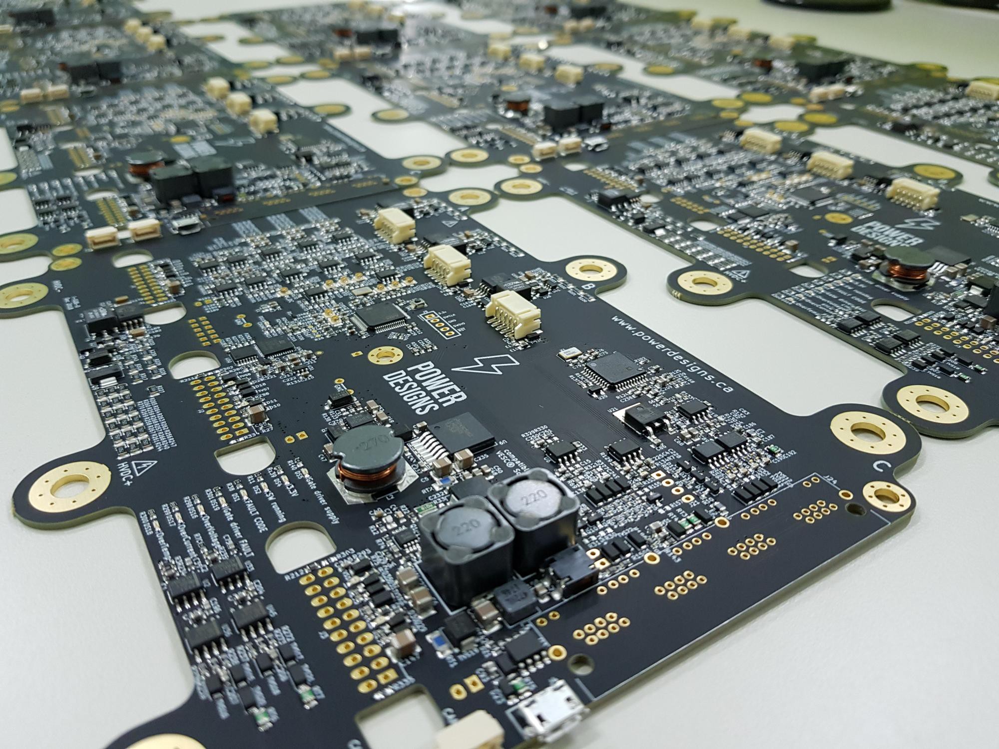
05/11/2019 at 00:09 • 0 commentsNew boards arrived!
Its a perfect chance to talk a bit about DFM using this small batch that showed up today as an example:
![]()
When Axiom -in its current form factor- started being prototyped I tried to keep all components in the same side. It is much easier for me to reflow soldering when they are only on one side of the board. Otherwise in the second reflow I always fear that some components in the underside will fall, its not a reasonable fear as I've done dual sided assembly a few times and it was never a problem... but the fear is there.
However the actual, tangible reason I avoid going dual side is because its a ton of extra work. You spend hours opening digikey bags, placing tiny components, dealing with your shaky hands, the solder paste mess, the hunger because once you start you can't stop, the backache, aligning the components to tolerances the human body isn't meant to resolve, and then you can sit and watch that satisfying reflow. When you have a 2 sided board, that soul crushing experience starts over again, and you didn't even get to see an LED turn on.
You need to go through that experience to really appreciate the *cost* of going 2 sided. You become aware of the steps that manufacturer needs to go through when you make that choice, exposing the board to 250°C twice, and it is really needed? It turns out that Axiom has enough real state available and a single sided assembly will do just fine, plus the underside of the board will be exposed to higher EMI and if the belly stays flat you can do some shielding and heatsinking. YMMV of course.
So single side it is, and in the picture above, you'll find that we only asked for SMT assembly, leaving out the through hole parts. There's 2 reasons behind this:
- Through Hole assembly is expensive. Or relatively expensive, we have an expensive BOM so it doesn't affect us that much, but is a place to save $.
- The TH parts pay import taxes in the country its assembled, plus import taxes in our country.
If we assemble TH locally we avoid both the assembler and a bit of foreign taxes, it makes sense for a small run.
Since this is our second small batch made for beta testers, our assembler has all the tooling in place, they won't charge you again for the stencil and pcb tooling, plus now they know the BOM, component location, they have your pictures, that amazing interactive assembly and several mails with instructions to assemble that first batch, so now its easy to produce more boards! You just say how many and ask how much, it's that easy. You've done all the heavy lifting optimizing your BOM cost, making sure you don't rely on hard to find parts, selecting different suppliers according to the price, etc.
And a quick tip: treat your manufacturer like a small child, be clear, go to town with as many drawings as you can and also listen to their suggestions. They are no childs, they are extremely competent and there are teams with technicians and engineers at your service, but you'll save time and money by just being graphical and verbose.
Its a long way to get to receive a well done batch arriving to your door, but that's barely the beginning! When they arrive you'll have to unpack the boards, and test them one by one. Axiom comes pre-programmed with a DFU bootloader in ROM that makes it possible to flash the MCU by just plugging the board over USB. In seconds we can check that:
- MCU is OK
- FPGA is OK
- Resolver chip is OK
- MCU supply rail is within tolerances
- Analog signals are reasonable (many of them should be at 1.65V for example)
- USB is OK
- Current sensor failure detection is OK
- Program vesc bootlader and the application so its ready to use
All that by just plugging it over USB!
Sooner than later we will need a jig to test that the analog signal path is within tolerances, test pwm outputs and comm interfaces, but for now, and since its a high end product we test each board directly with a powerstage. If the board can regulate 3A with those 425A sensors, your signal path is quite okay!
DFM does not end at the board level, Axiom design needs to take into consideration the mechanical assembly of the whole thing, including power stage, thermals, wiring, piping, bolt-screwing, torque-ing, the enclosure, and a long etc. Its not just a matter of avoiding collisions. But lets leave the mechanical side for another day, shall we?
Stay tuned!
-
Field Weakening Support
05/05/2019 at 04:42 • 0 commentsThat's right, Field Weakening!
A major milestone for the VESC platform! In our public repo we pushed the code to add support to FW to set the motor speed beyond base speed, and Max Torque Per Amp support, intended to drive IPM motors. We'll talk about MTPA in a future episode...
Without field weakening, a motor drive can only operate the machine up to base speed in the plot below. That's the constant torque region, you can achieve full torque in all that speed region, and then torque suddenly drops to zero.
![]()
With Field Weakening (FW) now the controller can make use of the extremely valuable constant power region. See it in action:
In the video you can see the Iq (torque generating current) in red, and Id (flux-generating current) in blue. When motor reaches base speed, a negative Id current weakens the field to decrease BEMF and allow more Iq current that produces torque.
Interior Permanent Magnet (IPM) Motors have a mechanically robust rotor structure that is effective in flux-weakening operation because it has low effective air gap. So, IPMSM can be operated not only in the constant torque region under the base speed but also in the constant power region over the base speed, and its the architecture most commonly used by OEMs in Electric Vehicles.
How it works?
As a motor rotates, it creates a back-EMF voltage across its coils proportional to the speed of rotation. In order to force current into the coils, the applied voltage must exceed this voltage.
The limitation comes when the speed of rotation is such that the required applied voltage is greater than the voltage available from the inverter electronics. At this point, the inverter can no longer supply current to the stator coils and the motor will not generate any torque. If the rotor is externally forced to rotate faster, the back-EMF voltage will exceed the power supply voltage, and current will attempt to flow from the coils into the power supply, producing a torque counter to the direction of rotation.
In practical terms, this means that for a given power supply voltage, and a required coil current, there is a maximum speed of rotation obtainable before inverter saturation occurs preventing more coil current from flowing into the coil. This speed is referred to as the base speed.In order to exceed the base speed, the back-EMF voltage must be reduced. Since the back-EMF is also a function of the magnetic flux between rotor permanent magnets and stator coils, reducing this magnetic flux will reduce the back EMF voltage. The inverter then does not enter saturation, current can flow into the stator coils, and the motor can rotate faster, although at the expense of reduced maximum torque.
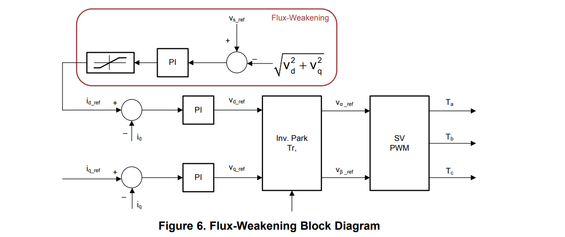
The basic principle of field weakening, as its name suggests, is to weaken the magnetic field strength of the rotor magnets, by applying an opposing magnetic field on the stator coils in phase with the rotor field. This is the direct axis (d-axis) in field oriented control, and acts to reduce the back EMF generated by the motor as it rotates.
The control scheme chosen to drive flux-creating current Id is based upon the following diagram, taken from a TI app note:
As always, to dig deeper into the new feature, you can check out our Pull Request on the VESC repository:
https://github.com/vedderb/bldc/pull/91
Alongside with the firmware code, we provided the patch for the user interface that adds the control of the new feature:
![]()
The hidden dangers of high speeds
So imagine that your motor without FW can reach 10000rpm on a 50V battery. Now you can actively weaken the field and reach 14000rpm, nice!
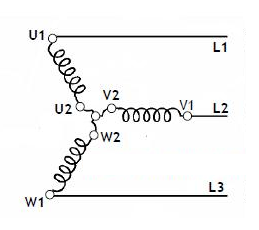
But what if for some reason your PWM is stopped and Id current suddenly collapses? Well, you better hold your hat because as Id collapses the magnets field will be restored and a very high BEMF will be generated. You are operating beyond base speed so BEMF will certainly be larger than battery voltage, and current will flow through the powerstage body diodes like this:
Only 1 phase is drawn for simplicity, but all 3 phases will contribute current.
That's an uncontrolled amount of current flowing to the battery, so a few things will happen:
- A large regen current will flow to the battery and the motor will act as a brake.
- If the powerstage can handle the current, great mechanical stress will happen with the possibility of losing the control of the vehicle.
- The current will flow into the battery for as long as the motor is above base speed, this could be milliseconds or several seconds, as its fueled by the inertia of the vehicle. Current could be well beyond 1kA, and the power dissipated by each body diode could reach several kW.
- If the powerstage can't take this amount of fault current, then the battery fuse or contactors should trip, and this unfolds another dangerous scenario: you are exchanging an uncontrolled current by an uncontrolled voltage. When the battery is disconnected it will no longer clamp the powerstage voltage and it will rise to whatever BEMF the motor is generating at that speed. Possibly destroying the inverter.
- Some applications allows a fault management that shorts the 3 motor phases if the load has a small inertia, probably not the case of an EV.
So back to our example of 10000 rpm base speed at 50V battery, which is typical for a small e-bike VESC, and you get a fault at 14000 rpm that halts your pwm. If your fault current is high enough to blow the fuse, you will have 140% of your battery voltage, that's 70V.
The problem is, those small VESC have an absolute maximum rating of 60V, so you will instantly blow your drive with big fireworks fueled by the vehicle inertia.
With an Axiom drive, the same principles apply, but since we use industry standard IGBT packages, if you have a 450V battery and you need FW to reach the speed equivalent to 800V, you have the possibility of swapping our recommended 650V IGBT for a 1200V part, thus allowing you to safely open the battery contactor the instant a fault is detected without causing damage and without the sudden and hard motor brake.
There are many ways to distribute the energy surge in a FW situation, we could explore them in a future log.
Unlike past logs, this feature has not been merged yet, and since its a critical and dangerous feature we are having some discussion before the PR is ready to merge, so stay tuned!
-
Block Diagram Explained
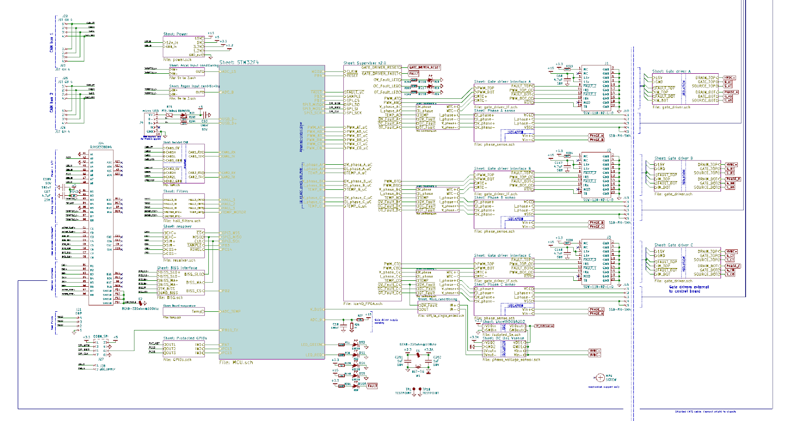
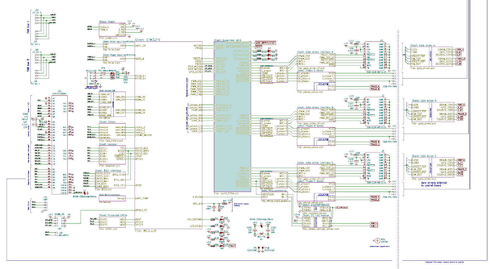
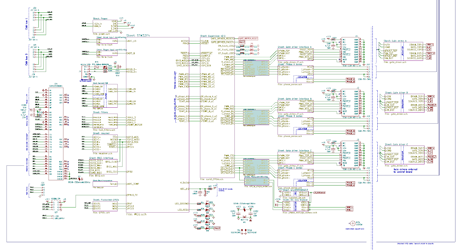
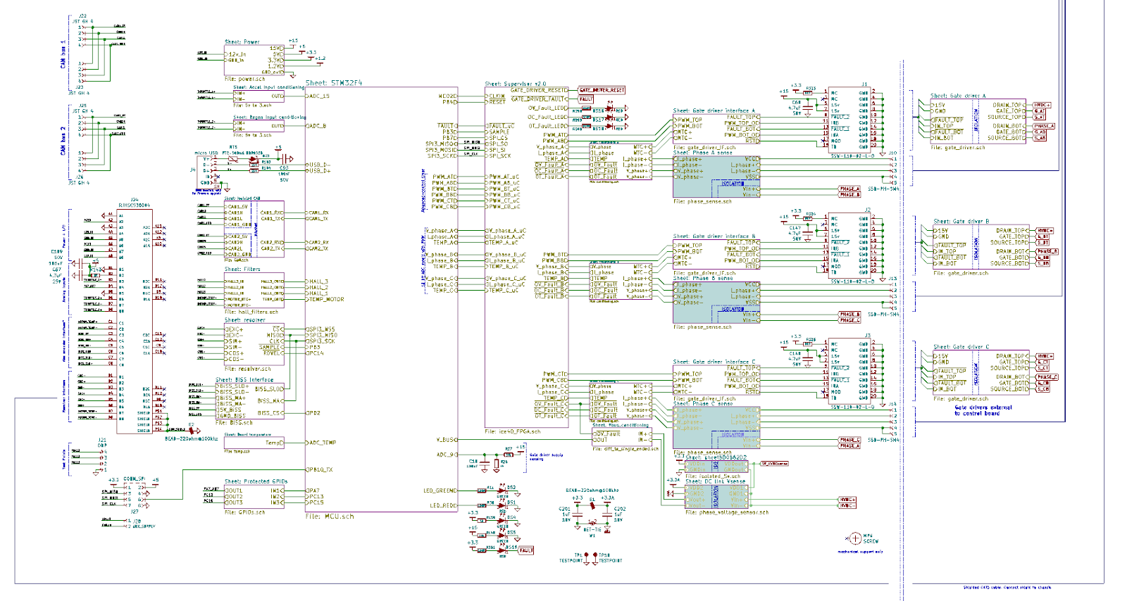
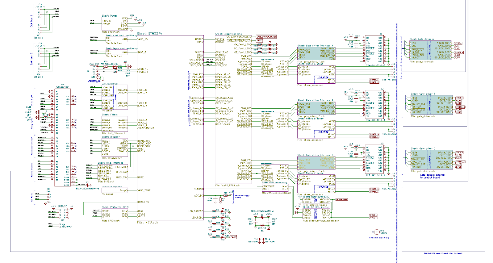
04/29/2019 at 11:40 • 3 commentsLet's take a closer look at what this piece of hardware is about:
![]()
The intent of the system block diagram is to highlight key components or subsystems, power/signal flow of interconnected assemblies and draw the reader's attention to how the components fit into the wider system. In order to read a block diagram (or detailed schematic), you would generally expect it to flow from left to right, with as much attention to the important details as possible.
Power Stage
In the top of the diagram you can find the powerstage of the inverter, generally consisting of the components exposed to high amps. From left to right you see:
- Terminals for the battery inputs. (BATT+, BATT-)
- A pair of isolation contactors (safety feature) and pre-charge resistors to limit the current during initial charge of the DC Link capacitor. (K1A, K2A, R32, R152)
- Voltage sensing of DC bus which is required for field oriented control (HVDC+, HVDC-)
- Automatic discharge of DC Link capacitor when system turned OFF or loss of MCU power.
- 600V 650uF DC Link capacitor, in this picture it is shown as three separate capacitors
- 650V 600A IGBT modules, mounted on a heatsink with thermal interface material
- 3 In-line phase current sensors, high bandwidth hall effect
- Active cooling system
- PMAC 3-phase motor
The powerstage shown is very specific for a particular configuration with 650V 600A IGBTs, but the customer can use a different powerstage, the control board is agnostic in this regard, with minor hardware changes the Axiom control board can be made to support other voltage or current ranges.
DC Link capacitance, ripple current and technology are chosen based on the application requirements (motor inductance, switching frequency, temperature, etc). For high voltage, power dense application metalized polypropylene (MPP) film capacitors are used. This type of capacitor not only has self healing capabilities, it is also capable of delivering a tremendous amount of instantaneous power due to extremely low internal impedance. The close proximity between DC Link capacitor and IGBT switches also minimizes the parasitic inductance which is critical for overall system performance.
For high performance drives 3 phase current sensors are necessary, they allow the control algorithm to manage signal noise and also to detect faults to ground. Furthermore, the use of three independent phase current sensors allow for controlling naturally occurring imbalance which otherwise not be available in a system with two sensors.
Control Inputs
On the left of the diagram there are user inputs
- CANbus interfaces. Redundant, isolated CAN bus. Supports UAVcan protocol and native VESC protocol at 500kbps.
- RJ45 1: 12V power input + digital I/O. The board can be supplied from 9Vdc to 28Vdc, 3A external supply is required, it is recommended to use a 12V battery to supply these subsystems. The board will generate all necessary control power such as 15Vdc for the gate drivers, 5V and 3.3V for the logic.
- RJ45 2: Analog inputs. Can be configured to be used as accel/regen inputs or sin/cos encoder.
- RJ45 3: BiSS absolute encoder port.
- RJ45 4: Resolver port.
- Hall sensor interface. This is not an appropriate position feedback for a high power, high performance drive, its there for testing purposes.
- USB port only for programming, not suitable for controlling a motor.
- SPI interface: internal SPI bus is available for very high speed expansion. In the existing design this interface is used for high speed communication between FPGA and MCU.
The fast switching of high voltage and/or high current can generate a considerable amount of electromagnetic interference (EMI). It is imperative that the input signals be protected against transients which is why the RJ45 type connector with CAT5 cable was chosen. CAT5 cable provides twisted pair with optional shielding which is ideal for signal integrity. CAN bus connector is the same as defined by UAVCAN specifications for direct mechanical compatibility.
The preferred interface for controlling a motor with an Axiom board is the CANbus as it provides CRC integrity checks, needs less wiring, can withstand more EMI than an analog signal and provides full access for both commands and readouts of the drive operation. Furthermore, as an open source product new CANbus commands or feedback can be easily accommodated with code future code customizations by the user.
Microcontroller Block
VESC uses an STM32F405 microcontroller which has the following capabilities:
- 168MHz ARM core
- 1MB flash
- 192KB RAM
- 12 bit ADC
- 12 bit DAC
- Advanced PWM
- Built-in USB DFU bootloader
- Open source toolchain, make and gcc based workflow.
- VESC firmware with 100,000+ lines of code and a RTOS.
The core of the system is the STM32 microcontroller, a high performance device that deserves its own post explaining the inner workings of VESC.
FPGA Block
While early versions in our design history used discrete logic, Axiom relies on an iCE40 FPGA from Lattice to perform continuous safety checks in fault inputs and pwm outputs. FPGA based protection allows for highly configurable and robust fault protection far exceeding simpler discrete methods.
Some highlights of the FPGA:
- QFN package
- 5280 Logic elements
- 1MB RAM
- SPI for on-boot configuration and data transfer.
- Internal PLL to boost clock up to 275 MHz
- Lightweight, open source toolchain
The FPGA has sufficient capacity to implement complex accelerator peripherals, like encoder decoders, digital processing; even a RISC V cpu softcore fits inside the fabric. It’s a great opportunity for research teams to push the boundaries.
Analog Signal Conditioning
The light blue highlighted blocks shown in the above picture receive raw, differential analog data which is filtered, converted to single-ended signals. Differential signal delivery was chosen due to their inherit common mode noise rejection and allow for larger voltage ranges. The conditioned signals are sent to ADC pins for further software processing, and they are also sent to a hardware based fast acting protection circuit in case of overcurrents, overvoltages or over temperatures. No software intervention needed.
High Voltage Sensing
Isolated inputs are used to sense the motor and battery voltages. Complies with clearance and creepage to work at 800V and uses an AMC1301 for reinforced isolated sensing.
Very high CMRR is required in applications with Silicon Carbide mosfets, and these isolators are well suited for those applications.
The battery voltage is constantly being used to compensate for ripple in the dc bus, and also during motor parameter detection. Phase voltage sensing measures the BEMF when the motor is released so the phase observer algorithm keeps track of the motor angle. That way, when the motor is released and suddenly the user commands full torque, the control loop knows exactly the motor position and can instantly apply the precise current vectors. Other uses include motor position feedback sensor calibration (encoder, resolver) and to monitor feedback failures during runtime.
PWM Output and Gate Drivers
The isolated gate drivers are external to the control board carefully matched to the IGBT installed. 3.3V PWM signals are generated by the microcontroller, processed by the FPGA and then are buffered and level shifted to 5V for higher noise immunity.
Follow us for more updates!
-
Current Sensor Failure Detection
04/23/2019 at 21:26 • 0 commentsFresh merge from VESC repository:
https://github.com/vedderb/bldc/pull/88
Last week we provided the code to handle 2 dangerous failure modes:
- Sensor/wiring damage
- Fault to ground
If a current sensor is damaged, the FOC will run out of control, with dangerous consequences. Axiom boards are the only VESC's that come with a simple pullup in the sensors input to make sure that a loose wire will set the analog signal to a known value that is detectable by the firmware.
So if the sensor offset is higher than a certain threshold, we trip the fault, it gets logged and visible from the GUI, and the controller won't be allowed to move the motor until the problem has been fixed. It will even let you know which sensor has an offset problem.
The second method used to detect a problem is checking that the sum of all phase currents is zero:
As you can see, the current can only flow through L1, L2 and L3, it has no other way to go, so the sum of the 3 currents should be zero.
In practice, under hard acceleration you can get to see some current flowing to the chassis, that's why we allow for a bit of current unbalance, and coded a low pass filter to avoid false trips due to noise.
Our boards are configured to trip at 130Amps of unbalance, and take around 0.3 seconds to trip, which is configurable in /hwconf/hw_axiom.h
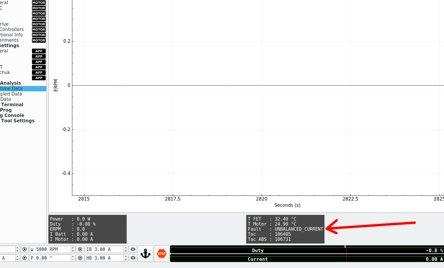
#define HW_MAX_CURRENT_OFFSET            620    // More than this offset (0.5 Vdc) trips the offset fault (likely a sensor disconnected)
#define MCCONF_MAX_CURRENT_UNBALANCE        130.0    // [Amp] More than this unbalance trips the fault (likely a sensor disconnected)
#define MCCONF_MAX_CURRENT_UNBALANCE_RATE    0.3    // Fault if more than 30% of the time the motor is unbalanced
Here's a quick video showing a fault:
VESC Tool GUI showing the FAULT:
Our commits came with this protection disabled to the rest of VESC hw versions, but it was soon added to all the hardware variants!
-
Continuous flash memory checking!
04/20/2019 at 13:35 • 0 commentsSo here's something the average build does not have:
A thread running in the background continuously checking the integrity of the flash memory!
So while your high performance powertrain is crunching numbers, running a 30kHz control loop, communications, fault management, and perhaps simulating a motor, it is also checking the integrity of the flash memory in the background, crawling along the whole flash map making sure the hardware-accelerated CRC calculations perfectly match the expected values. If they are not, board is reset.
After reset, another full integrity check is performed, if it fails the firmware will loop forever making sure your corrupted binary does not do any damage!
Background checking is inspired in a safety-related app note:
![]()
It runs on a low priority thread on the RTOS, at light OS loads it looks like this (note persistance is ON to see the jitter), crunching a 8kB CRC block in ~300us.
![]()
When you really push VESC with many hard realtime tasks, this thread takes the back seat for a while and takes about 1ms to compute.
![]()
Overall, flash memory integrity check task looks like this
![]()
After merging a couple of days ago with the VESC master branch the checker settings got a bit tuned, now it calculates 1kB chunks at a time, every 6 milliseconds.
With any other VESC out there a a flash memory failure would definitively brick your board, but not with an Axiom! This control board lets you use a ROM-based DFU bootloader, so if you brick the board, just connect Axiom to your computer over the USB interface (no uart adapter required) and load a new image directly with an dfu loader program (one-liner in linux, a few clicks away in windows).
Pull Request discussion here:
https://github.com/vedderb/bldc/pull/87
And just like Formula 1, this high end trick is now already available of thousands of small VESC users, just a firmware-upgrade away.
Well, I guess now the average vesc build does have this neat feature.
-
Motor Simulation and Sin/Cos Encoder Support
04/15/2019 at 00:06 • 2 commentsToday some code we developed for the VESC platform was merged into the master branch, reaching thousands of current VESC users.
Motor simulation inside the firmware is a critical step in our path to having the greatest controller out there.
- It help us to develop new control algorithms. For example Field Weakening, MTPA (Maximum Torque Per Amp), new flux phase observers, etc, without risking to damage expensive hardware.
- It opens the door for deeper automatic testing. We are now a script away of being able to check that the code can actually run a motor. It sounds easy enough, but with many commits getting merged, and so many hardware configurations to support, this kind of hardware in the loop will detect problems way sooner, and way cheaper!
It runs in cpu time, you can halt the debugger, take a look, and resume operation. Or you can perform slow code coverage tests to ensure you have exercised all the lines in your code, often required by some industries.
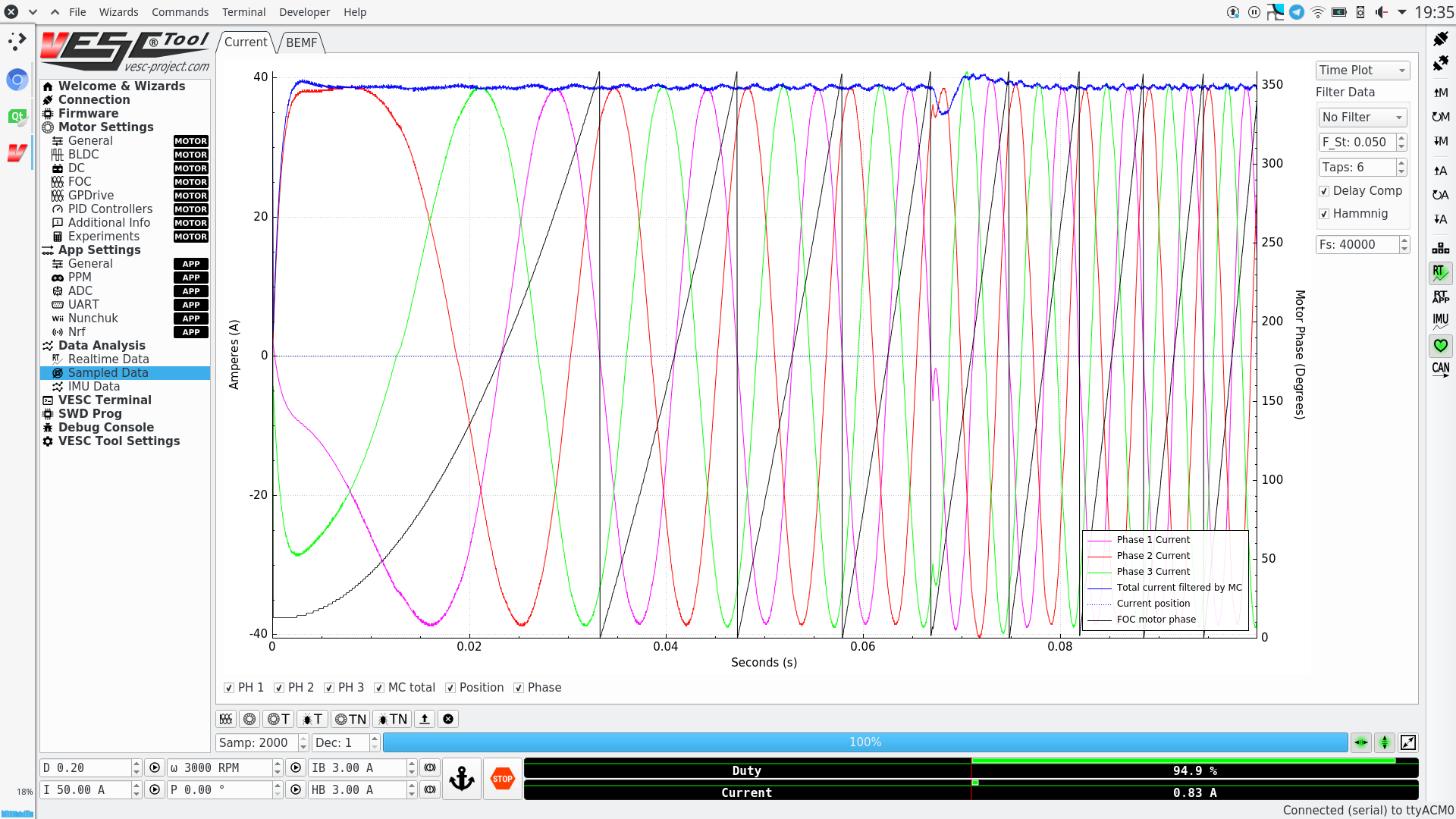
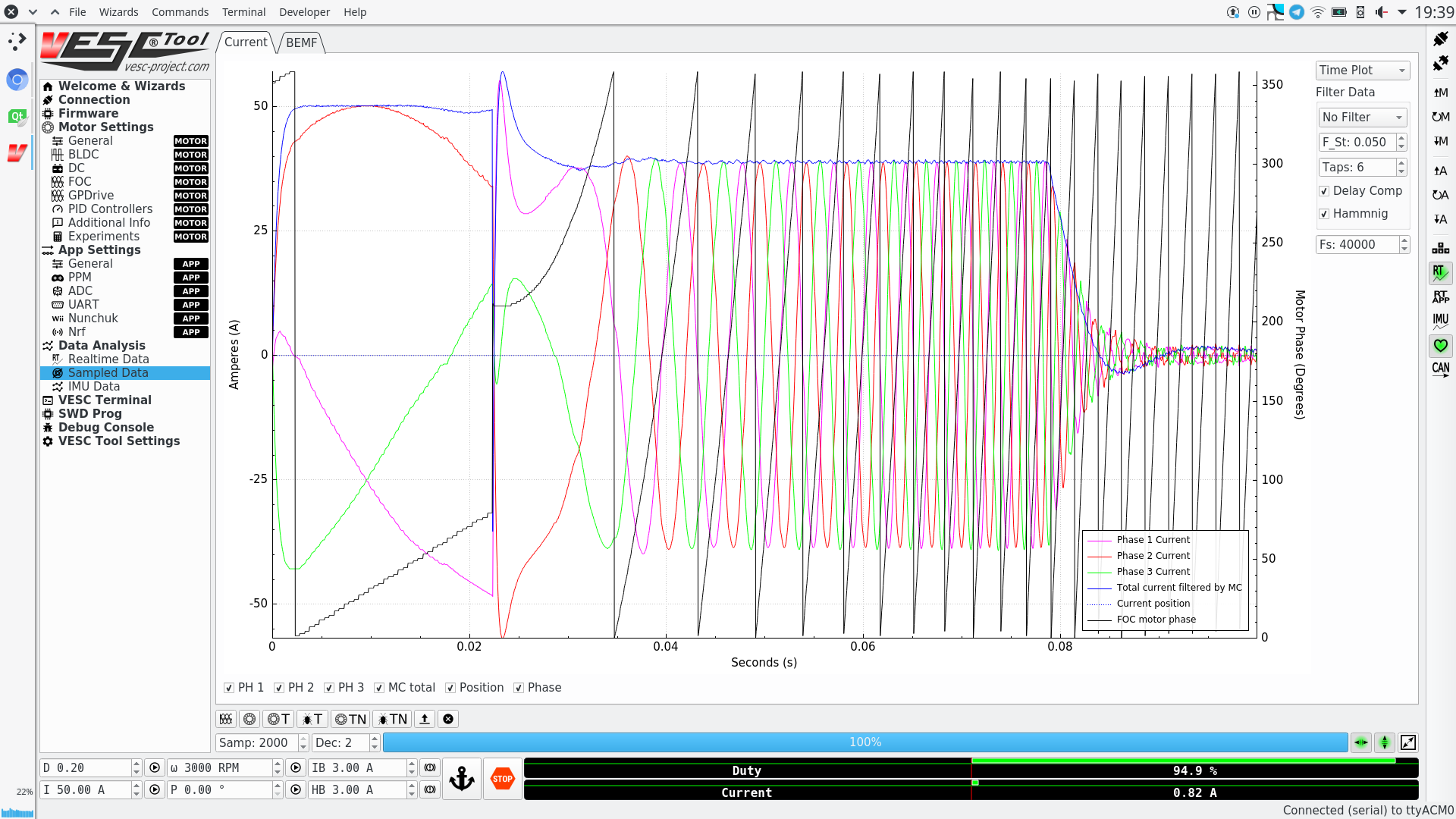
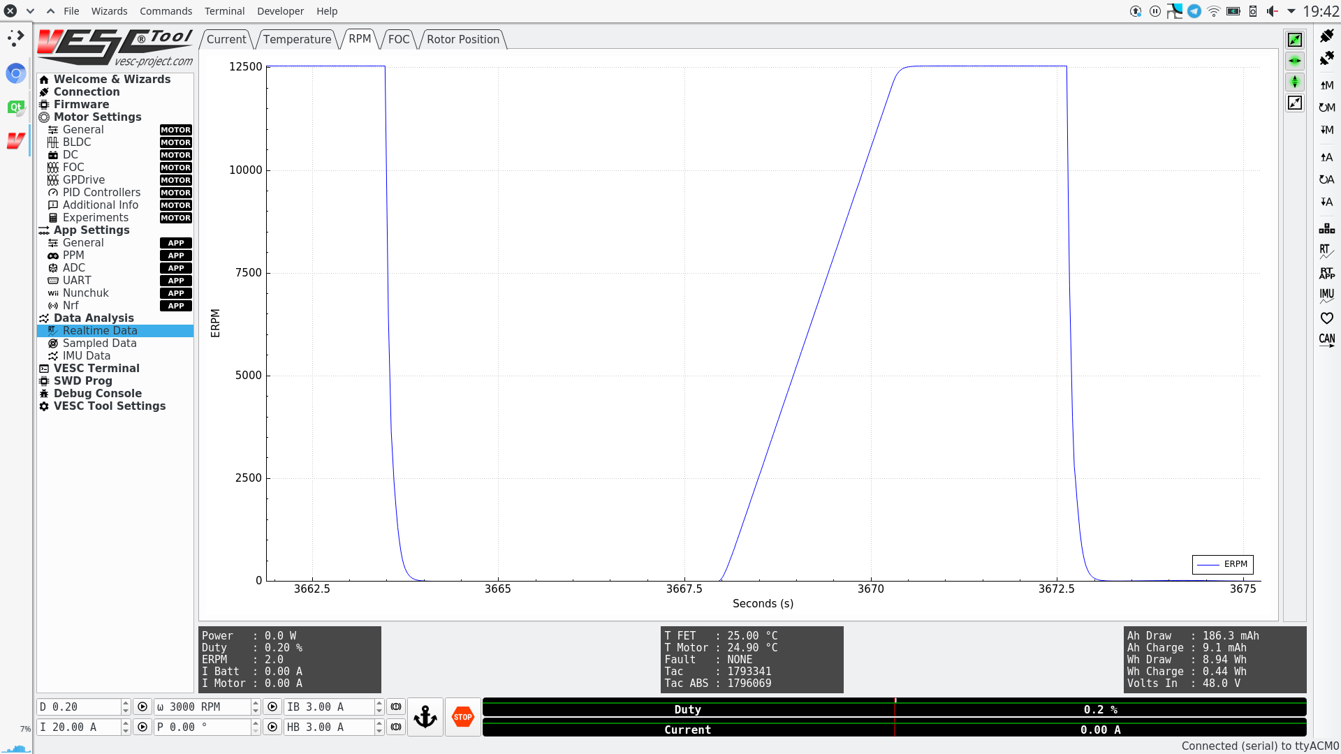
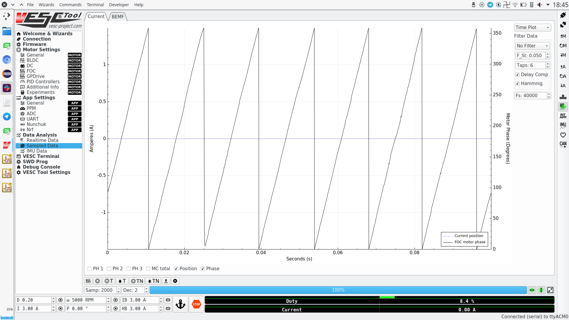
Here is a screenshot of a motor startup being simulated:
![]()
![]()
![]()
The virtual motor is modelled as an IPM machine, and is engaged from the VESC Terminal inside the GUI.
More details in our Pull Request
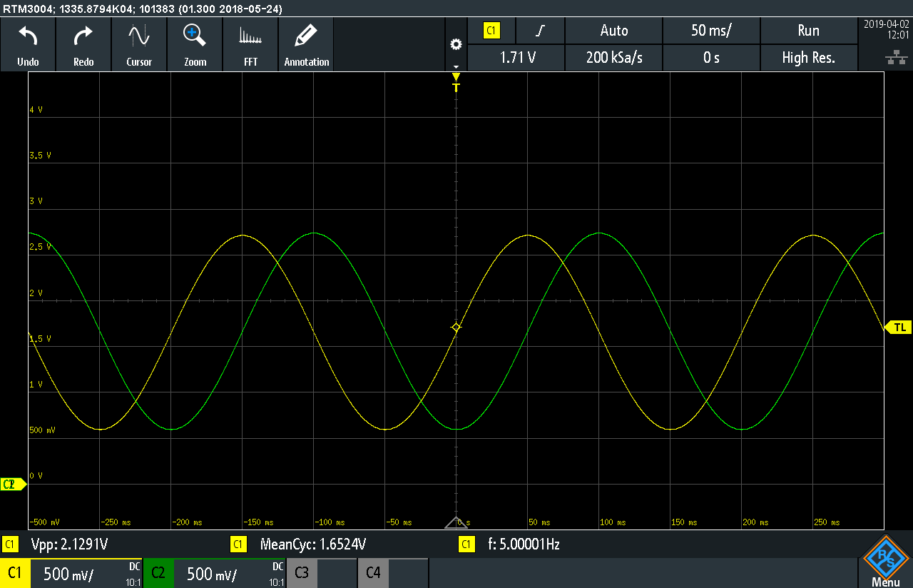
The other piece of code we authored is Sin/Cos encoder support. These encoders provide absolute rotor angle feedback, no need to wait for indexes. They provide 2 sinewaves in quadrature, and by reading that signal the code can calculate the rotor angle.
Medium power motors are commonly using this kind of feedback. Zero bikes use them for example.
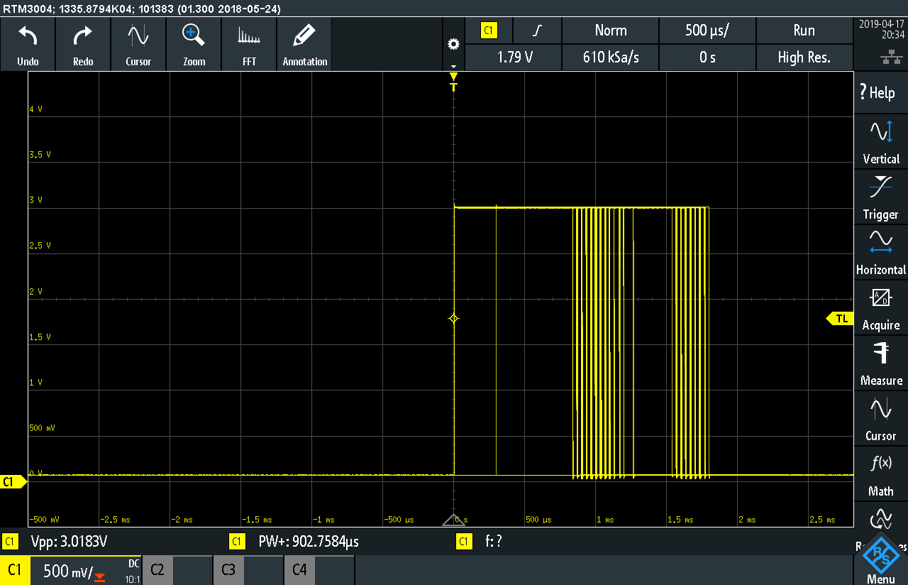
Here is the signal input:
![]()
And resulting phase measurement:
![]()
Here is the Pull Request, and the line of code that calculates the angle
-
Launching Social Media!
04/12/2019 at 21:17 • 0 commentsFinally, Axiom has a website!
Head to www.powerdesigns.ca for more info and to get in touch.
And we have a brand new facebook page
https://www.facebook.com/powerdesigns.ca/
And twitter!
https://twitter.com/PowerdesignsC
Stay tuned!
Axiom: 100+kW Motor Controller
High Power, High Performance 400V 300A 100+kW Motor Controller fully compatible with VESC®