-
PCB layout
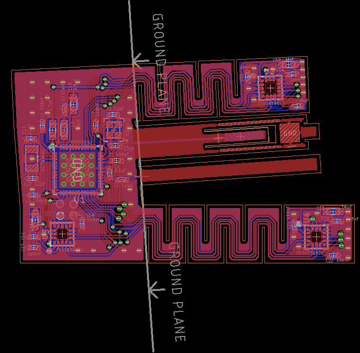
04/15/2019 at 23:26 • 0 commentsThe angles made the a particularly tricky board to lay out because of the angles. To route the traces on the angled flanges, I measured the angle in fusion360 and rotated the entire board to align the angled flanges with the x-axis. Eagle had a bit of roundoff error that would create design rule violations when I rotated the board back after routing the traces, so I had to micro-adjust the traces (or more often the board dimensions) to correct them.
I suspect that bending the antenna might change its behavior - I will have to test that once I have the boards - I should probably add in a U.FL connector to make testing a bit easier.
normally for a 2 layer board I would stitch the top and bottom ground planes together with vias along the edges, but 1) I didn't have a lot of space for that, 2) the weird angles made it difficult to get even spacing, and 3) I was worried that putting a bunch of vias right next to the edges that I was going to be bending might cause the board to tear instead of bending. Instead of stitching the ground pours together around the edges, I just stitched them together in a grid.
![]()
-
Designing the schematic
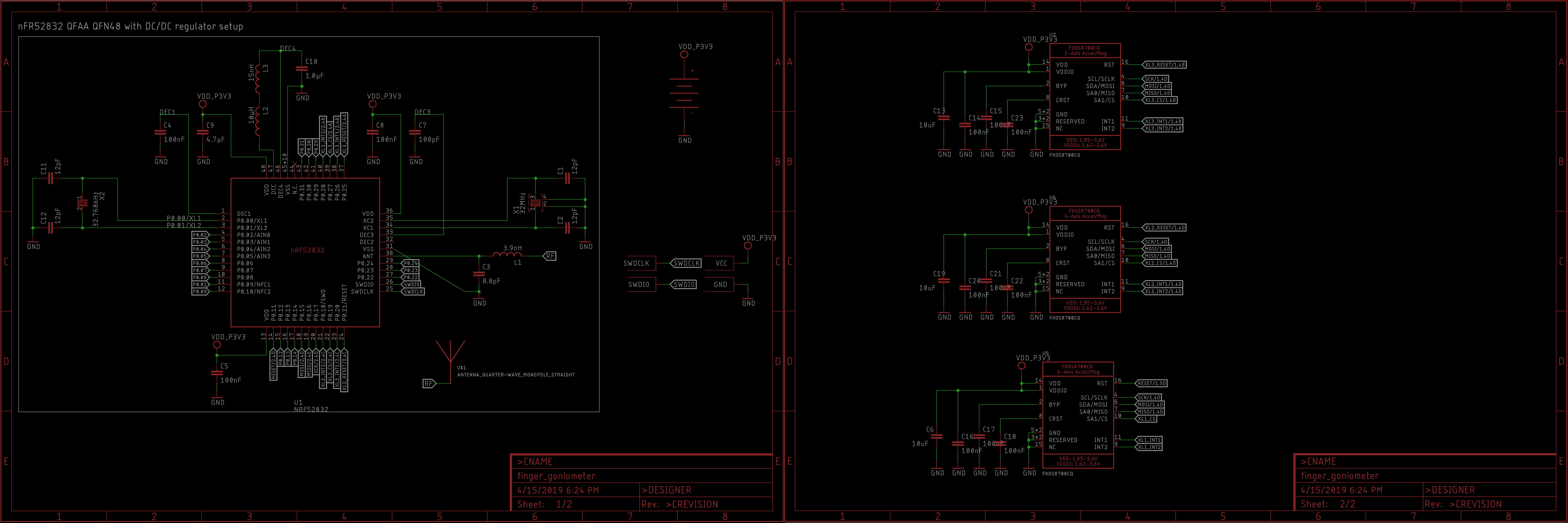
04/15/2019 at 23:05 • 0 commentsAs alluded to (but not explicitly stated) in the previous log, I am layout out the board in Eagle.
In keeping with the goal of simplicity, I just used the design block for the nrf52 published by nordic semiconductors. The nRF52 has two internal regulators, an LDO regulator and an optional buck regulator. The buck regulator requires a few extra components, but it can save power in some circumstances. I wasn't hurting for space, and I expected that I would need all of the power savings I could get, so I decided to use the design with the extra components for the internal buck regulator.
for the accelerometer/magnetometers, I got the eagle library files from adafruit. Thanks adafruit. Thadafruit.I decided to experiment with building the battery contacts into the flex PCB. we will see how well that works.
![]()
-
Defininf the outline of the flex pcb using sheetmetal tools in fusion 360
04/13/2019 at 20:27 • 0 commentsNormally for a project like this I would start by designing the PCB, but for this particular project, form factor is very important. The PCB needs to fit onto the back of the hand and the sensors placed over the fingers need to have the freedom to bend with the fingers.
I will be using a flex-PCB for this project, and since the value of flex-PCBs comes from their ability to confirm to 3 dimensional structures, it makes sense to design the outline of the board using a 3d cad tool instead of a normal 2 dimensional PCB cad tool.
![]()
The sheetmetal tools in fusion 360 are perfect for designing 3 dimensional structures that need to be able to unfold into 2 dimensional designs. I sarted by making a quick sketch for the back of the palm and then extended flanges out for each finger.I added serpentine cuts into the finger flanges to try to give the board more freedom to bend laterally, but I am not sure they are going to work well enough. If they don't, then the flex PCB will probably tear when the wearers fan out their fingers.
Between the two fingers, I extended out two more sections for the battery and the antenna. Unfortunately, I had to put the flange for the antenna very close to the flange for the battery. It would have been better to put it off to one of the sides, but that would have doubled the overall size of the design. For now I think it makes more sense to see whether putting the antenna near the battery causes serious problems.
Once all the key features were in place, I used the "unfold" command in fusion 360 to create a flat pattern for the design, which I exported as a .dxf file.
Because fusion 360 and Eagle are both owned by autodesk, it is very simple to import a dxf file generated by fusion 360 into Eagle. Oh, wait, no. It actually doesn't work at all. I had to open the .dxf file in inkscape and re-save it before importing it into eagle using the import-dxf.ulp. I also had to replace all of the curved segments with straight segments. After doing that though I was able to import the outline I made in fusion 360 into the dimension layer in eagle.
Goniometron the Flexinator
As you bend, so bends the board. The board bends in many fields, and with it bends the truth. The truth passes through the air.