 CapitanVeshdoki
Here it is. Resistor connected to ground directly this time!
First of all I noticed stronger magnetic field, as well - low-frequency oscillations. I was happy about that and that is what I've seen on gates of MOSFETS:
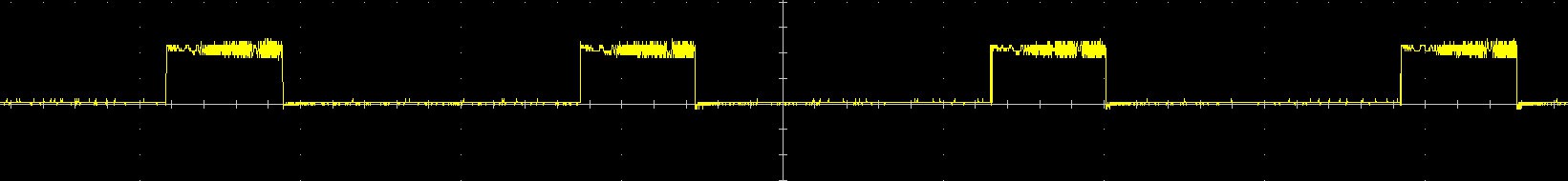 196Hz square wave, Nice!
As predicted, everything was great on I_COIL input too:
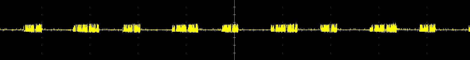 (Yes, time/div on this pictures isn't same, but length of impulses is same for sure)
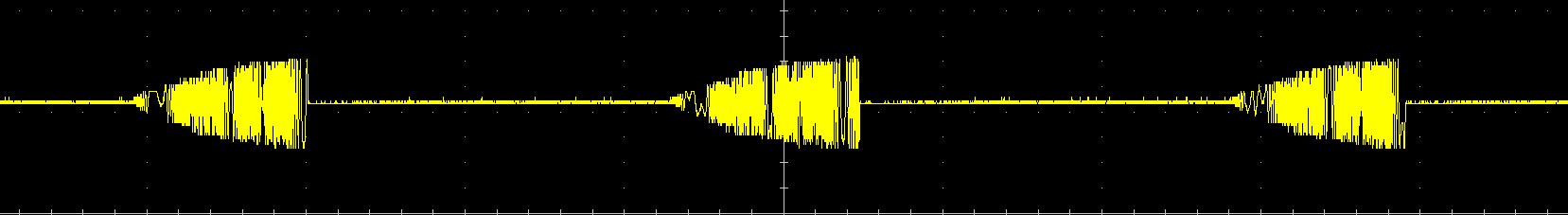
And on capacitor:
Then I felt very frustrated, I realized what reference voltages (which should affect energy boundaries) unable to change behaviour of board much. And then I discovered that:
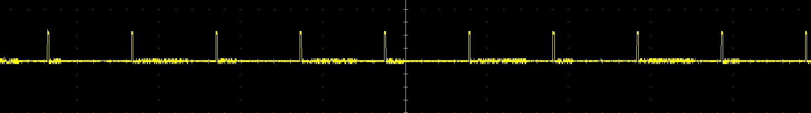 What it means? It means what output from Arduino is just PWMed thing, no DACs magic at all!
 And I don't think what it's any good for our circuit, then it seems what some low-pass filter is needed... Or I would connect that to the voltage dividers, temporary, because it's easier and works pretty well.
Overall, everything is going as needed.
I can't say much about retaining of energy now, but if you very curious:
- Board consumes 30mA
- As you can see from control signal on gates, there is 30% duty cycle
- Usually it consumes around 270mA (connected directly to PSU)
- So it retains about 60%+ of energy somehow!
(even with wrong behaviour of PWMed reference voltages)
Discussions
Become a Hackaday.io Member
Create an account to leave a comment. Already have an account? Log In.