 CapitanVeshdoki
-
Evaluation board
10/31/2020 at 12:54 • 0 commentsIt seems it's gonna be optimal to freeze that project for a while, but beforehand I decided to make a summary of some sort: that EMF retention technique worked well, making schematics and PCB available is gonna be great for someone willing to experiment with it. Also, previous versions were kinda clumsy, I've learned a little from other stuff I designed recently
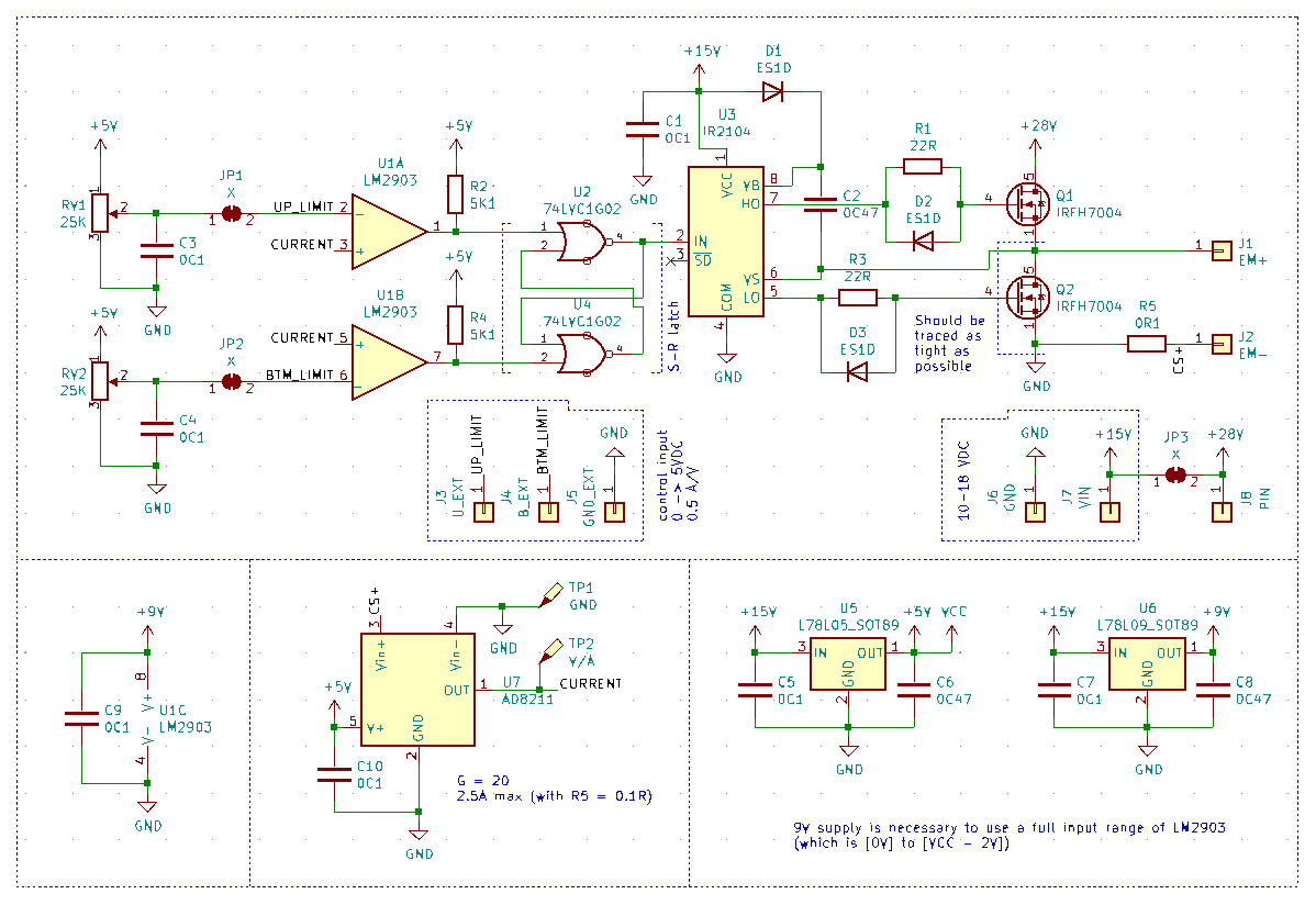
![]() That version won't high voltage very much, main focus was onto providing lowest possible resistance near Q2. 40V IRFH7004 were a best choice from what was widely available in my country. Higher voltage means higher efficiency, but hey, most of benchtop power supplies are 0-30V or close to that, should be fine : )
That version won't high voltage very much, main focus was onto providing lowest possible resistance near Q2. 40V IRFH7004 were a best choice from what was widely available in my country. Higher voltage means higher efficiency, but hey, most of benchtop power supplies are 0-30V or close to that, should be fine : )
Using solder jumpers you can choice between using two PSU (up to 28V) and one PSU (18V max) arrangements. Also, there are two potentiometers to adjust upper and bottom current limits, which you can disarm in similar fashion, by desoldering JP1 and JP2, to use it with some external controls if you wish (0.5 amps/volt, 0->5VDC with a stock 0.1ohm current-sensing resistor)
Oh, and AD8211 is used there to provide somethat better on-state resistance capabilities, as it provides 20x gain. Anyway, typical electromagnet has a resistance around 15ohms or so. I chose 0.1ohm since lower values are NOT widely available here (that is funny), it's not like I'm a fan of 1W THT resistors or anything , )![]() It should look something like that. Important to notice, that PowerPAK-8 housings were not devoted for high-current performance, but only for extremely low channel resistance. Actually, Q1 can be any el cheapo mosfet, only Q2 is critical, like that it looks cooler, though, ahaha
It should look something like that. Important to notice, that PowerPAK-8 housings were not devoted for high-current performance, but only for extremely low channel resistance. Actually, Q1 can be any el cheapo mosfet, only Q2 is critical, like that it looks cooler, though, ahaha
Would take a couple months to get that from China, if it works properly - gonna upload gerber files e.t.c. for public use. With a little explanation on what it does, to rewind that here are 2 posts available:
Post 1
Post 2 -
Optimizing magnetic scheme
08/31/2020 at 23:31 • 0 commentsPermanent magnets can trick you into thinking, that 20kg of attraction force is easily achieved. Everyone seen electromagnetic locks, some can do almost 500kg of holding force! However, magnets from electromagnetic locks differ from rare-earth ones, since rare earth magnets can do the same with very long magnetic loops, gangsta!
Achieving something similar without superconductive magnets is quite tricky. So for almost a year I worked onto control circuit that can maintain EMF without converting it into heat very much. And even got some great results, however with current semiconductors it helps 50/50: very impressive overall, not enough for my application. So...
It's obvious for me now, but month ago it truly wasn't : )
There was something that can be done with magnetic "design":![]() There, poles of an electromagnet are pretty close to poles of a permanent magnet (or steel bar), with that in mind it's closer to electromagnetic locks, while by trying to align magnets, it still has somewhat nice operating range.
There, poles of an electromagnet are pretty close to poles of a permanent magnet (or steel bar), with that in mind it's closer to electromagnetic locks, while by trying to align magnets, it still has somewhat nice operating range.
How gap affects force? I've made a simple setup with my desktop CNC to sorta map it:![]() As I use parts from an old disk drive as a linear rail for magnet, it had a very noticeable friction. Also, linkage between scales and a moving magnet wasn't perfect, as it tended to be springy...
As I use parts from an old disk drive as a linear rail for magnet, it had a very noticeable friction. Also, linkage between scales and a moving magnet wasn't perfect, as it tended to be springy...
But that was enough to get needed data:![]() As you can see, gap affects performance very much. I can make an educated guess that it would be full holding force with a gap shrinking to zero. That means that some tolerance in making artificial muscles, as it is for now, is needed to make them perform well
As you can see, gap affects performance very much. I can make an educated guess that it would be full holding force with a gap shrinking to zero. That means that some tolerance in making artificial muscles, as it is for now, is needed to make them perform well
Hopefully, it shouldn't affect their semi-softness
P.S. Summer is over, uhh
P.P.S. Someone knows when JapanPost will resume shipping worldwide? I have ordered a pair of mugs half a year ago, they are still there, ahaha, it's really confusing -
BLDC controller bughunting
06/05/2020 at 23:56 • 0 commentsTime to time work with electronics is deeply confusing.
You may have 3 identical FET drivers connected same way, but still - only specific one burns out. Again and again. I've changed resistance (Rgate), and it seems that situation with heating improved a lot (switching now occurs in a neat way, without confusing oscillations, I was impressed: originally thought that high control currents would make everything better, but it seems that they require a bit more thoughtful layout with damping circuitry)
However, one transistor from six still overheats, low-side. Reason is simple:![]() It never got sufficient voltage to fully open. I have no idea why one of sides died this time, or maybe it's components around or flux remained on a PCB? Hope I would find a reason. If not - I will make new PCB for trials with dip panels for drivers to change them without tedious unsoldering procedures.
It never got sufficient voltage to fully open. I have no idea why one of sides died this time, or maybe it's components around or flux remained on a PCB? Hope I would find a reason. If not - I will make new PCB for trials with dip panels for drivers to change them without tedious unsoldering procedures.
While producing prototype of CDI (maybe I would release it as OHW at some point) I found my personal favourite way to manufacture PCBs at home. Previously I tried to mill them entirely, however it's time consuming if you want to remove a lot of cooper (and you usually do), it seems that with a cheap router you can get much greater result by combining etching and milling holes + board outline -
BLDC testing rig
05/25/2020 at 20:10 • 0 commentsLong time no see!
For two months melancholy was my companion, but it seems that season ended x)
And I want to introduce BLDC testing rig, as stated somewhere above. Here it is:![]() Designed to measure thrust generated by a propeller, for that purpose there is an electronic weight in place. Why thrust, you may ask? There is an interesting relationship between thrust and output power - it's perfectly linear. If that setup would generate more thrust with methods suggested before, it would mean that it is more effective, definitely. Even through it seems to work, it should help to get more convincing numbers, I'm not talking about power measured in watts, since it requires different rig, but in terms of how output power relates it does it's job.
Designed to measure thrust generated by a propeller, for that purpose there is an electronic weight in place. Why thrust, you may ask? There is an interesting relationship between thrust and output power - it's perfectly linear. If that setup would generate more thrust with methods suggested before, it would mean that it is more effective, definitely. Even through it seems to work, it should help to get more convincing numbers, I'm not talking about power measured in watts, since it requires different rig, but in terms of how output power relates it does it's job.
Unfortunately, "controller" has a tendency to burn on voltages higher than 10V, that limits output power it's capable of and I cannot get any trustworthy readings of such a small thrust with those scales. It's important to take friction in account as well - with more powerful hardware impact of a friction would be insignificant.
Though I possibly can use high currents, FETs heat up and I need to solve that problem too. In a next iteration of a design. Thing is - I hardly can see any difference between widely used ESC's schematics and my design, no special protection there (may it be board layout?)
Now I'm quite busy with a deadline of other project, I don't think I would return here with a new version of a BLDC-thing in near future but who knows, maybe I would find that small mistake in circuitry and make current version work -
BLDC alpha-test!
03/14/2020 at 17:43 • 0 commentsI fixed that board from previous update. I wasn't carefull enough and forgot to connect some nodes together, and though MOSFET drivers still die when I power everything with voltages greater than 10V (dV/dT problem?), under that everything works fine. So, I tested it out and it worked out. Hooray! : )
It turned out, that it's pretty complicated to measure maximum power output of a BLDC and it's similarly hard to measure certain effects by an oscilloscope as everything is very noisy. Inappropriately noisy! After a bit of confusion I utilized the fact that motor won't start being underpowered, then - compared modes with and without "advanced" retention
As you can see, it utilized power more effectively with retention. Can't say "how much" in numbers, yet it means that there is a room for further improvement at least! It's great that even first steps in that direction give some noticeable results. That means lesser heat irradiation and higher power density are possible -
BLDC controller trials
03/05/2020 at 19:04 • 0 commentsI had an intention to use amazing PowerPak housings for transistors. And guess what? I managed to fail that twice by assigning things to a wrong pins. Firstly, I messed with a gate and after milling second version I realized that drain and source were swapped. So... I soldered TO-220 instead. Here is a picture of board's better years:
![]() PCB at the bottom would serve as a measurement tool for testing bench, it has 12bit DAC and instrumental amplifier with adjustable gain to measure torque. More of that in next updates as there is some problems with that controller. It works, overall, but "rings" like crazy. Here is a photo with re-soldered FETs and voltage on transistor's gates:
PCB at the bottom would serve as a measurement tool for testing bench, it has 12bit DAC and instrumental amplifier with adjustable gain to measure torque. More of that in next updates as there is some problems with that controller. It works, overall, but "rings" like crazy. Here is a photo with re-soldered FETs and voltage on transistor's gates:![]() Looks suspicious! I don't know what's the reason for that. Maybe, protective zener diode cause some problems. But the fact is that even without motor connected it drains noticable current and produces sound. Sound which is normally produced by a great currents flowing through tiny components. It's not a norm : )
Looks suspicious! I don't know what's the reason for that. Maybe, protective zener diode cause some problems. But the fact is that even without motor connected it drains noticable current and produces sound. Sound which is normally produced by a great currents flowing through tiny components. It's not a norm : )
P.S. Though, transistor opens as needed, shape of a current is an accurate representation of what we see on the gate, I presume - driver works fine, but frequent switching caused by ringing (around 1MHz) overloads it. Will see! -
Full-fledged theoretical "How-to"
02/04/2020 at 13:52 • 0 commentsHello! Made a site to publish theoretical info in convenient manner
![]() http://cafeohw.xyz/electronics/eism/
http://cafeohw.xyz/electronics/eism/
^ You can check it via that link -
BLDCiing it forward
01/21/2020 at 21:11 • 0 commentsNext logical step - is to couple theoretical findings with BLDCs, it is fun, educational and even useful at some point! In previous update that was a brushed motor... Pretty unfortunate - it's hard to imagine worse enemy than brushes with that approach.
I started to develop an experimental BLDC controller and imagine my surprise when I realized that circuitry, mentioned in previous posts, fits there ridiculously well! People, familiar with BLDC controllers, would probably notice that there is not much to change. Of course, specific control methods required and some hardware tweaks also, but hey, it's pretty neat : )
Generally speaking - there are high/low side FET's connected to each phase of BLDC coil, therefore there is an opportunity to shortcut coil from GND to GND via that. Or from VCC to VCC. Providing low-resistance path for a current, low voltage drop and so on... (topics from previous posts)
It's pretty pricey to implement analog current-control for each phase (thanks to DACs, low resistance and preferably hall-effect current measuring ICs, logic e.t.c.) - in this iteration, I decided to use old-fashioned way, outsourcing computational power and commands from an external MCU. Not the most elegant solution, neither a reliable one. Let's hope, that it would work without occasional fireworks.
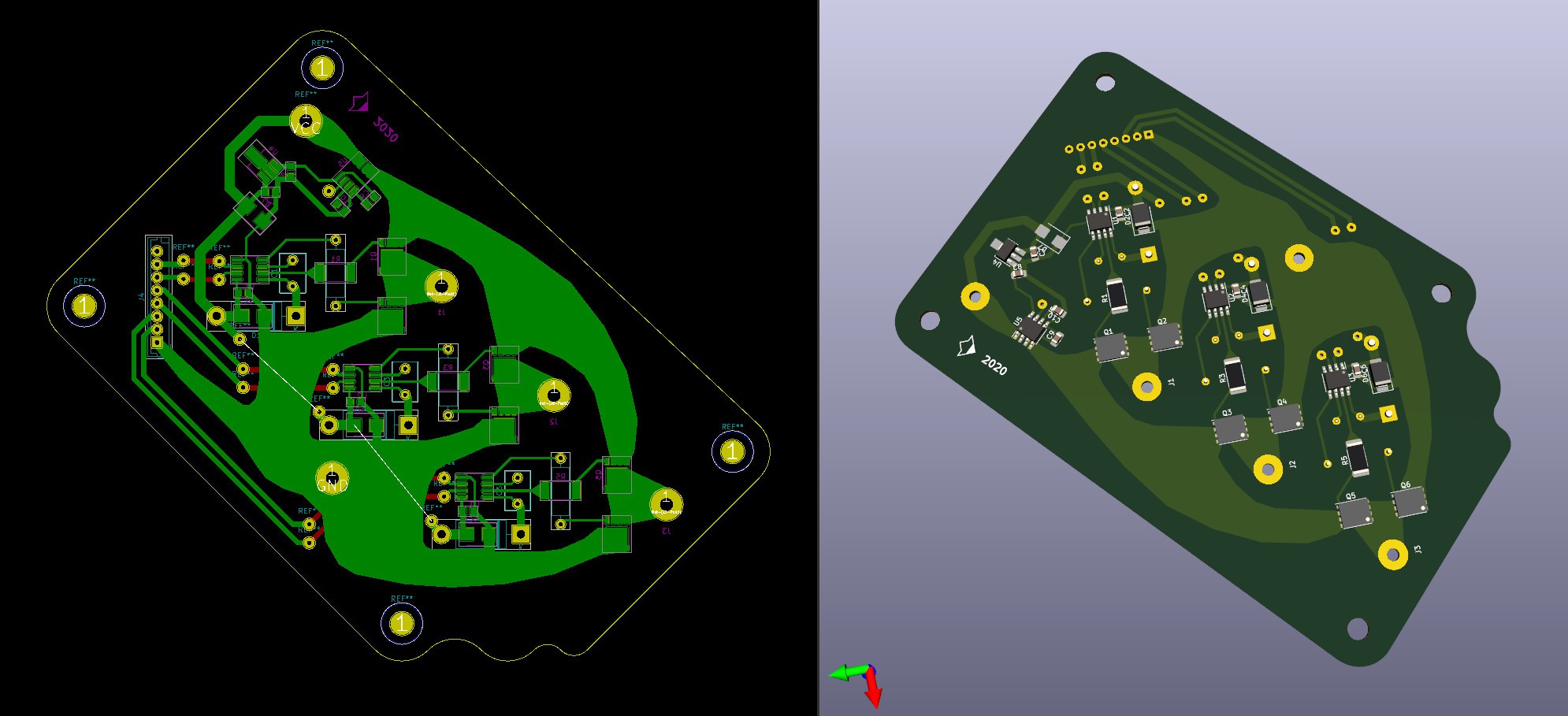
Compromise is to use onboard timer and only ON/OFF signal to switch coils would be sent externally, however it would be a tedious process to make it on one layer board, with all required logic IC's. Simplified everything to a maximum degree possible, with one current sensing IC for all 3 channels:![]() Had lot of fun tracing that stuff! Aside of queer shape, it should have a damn good resistance and heat dissipation properties. Inductance should be less as well.
Had lot of fun tracing that stuff! Aside of queer shape, it should have a damn good resistance and heat dissipation properties. Inductance should be less as well.
Not sure, that I gonna manufacture this one soon, so there is a room for corrections.
I'd like to make traces which go from drivers to a gates wider, as I see it now
(there are interesting 4A source/sink MOSFET drivers)
P.S. And that is our test subject!![]() Motor has something around 30mOhm resistance, according to a manufacturer. Curious how it would play out, generally - low resistance would be a benefit, but with MCU-controlled board I'm pretty concerned about switching frequency. It's really easy to get sky-high currents that way x)
Motor has something around 30mOhm resistance, according to a manufacturer. Curious how it would play out, generally - low resistance would be a benefit, but with MCU-controlled board I'm pretty concerned about switching frequency. It's really easy to get sky-high currents that way x) -
DC motors?
01/18/2020 at 14:47 • 0 commentsThis time I've got a more direct reading than current. Pivoting torque.
Before that, traditional links list:
Theoretical parts:
- Part 1 (how efficiency works while you charge an electromagnetic field)
- Part 2 (why discharge time matters and how it affects heat dissipation)
- Part 3 (that one was half-wrong, but heat dissipation part is likely to be true, read carefully)
- Part 4 (what affects discharge time)
- Part 5 (how to discharge field slowly using MOSFETs)Current is a great reason to assume that magnetic field is somewhere... there, but not that convincing - I can imagine some unaccounted nuances, there are lots of them, usually. And people try to decrease their amount by doing further research.
It was necessary to prove, that along with current it produces appropriate force, as we use unusual methods to work with an electromagnetic field here, so I made that thing:
![]() That photo magnifier was unused for years! But it came in handy, finally
That photo magnifier was unused for years! But it came in handy, finally
On a right side there are digital scales. Fun fact, that they even have temperature compensation. I was really impressed with that, since they were pretty cheap. What I did - I checked, that with virtually same average current, pivoting torque is the same:As I mentioned in video - it works. Generally speaking - to maintain magnetic field, all you need is to counteract it's discharge rate on slow discharge phase and heat loses on a charge phase. In this experiment I've got this:
1) I^2*R on a coil, about 8W
2) Power, required to charge 3mH coil from approximately 1.3A to 2.2A 1000 times per second, about 5W
Since duty cycle was 50%, we have (8W)/2 + 5W = 9W average.
And it's important to notice, that only 4W goes to heating of a coil, compared to 8W with traditional methods
Conclusion:
- By decreasing resistance of a coil OR by increasing voltage we minimize heat loses
- By decreasing voltage drop across slow discharge circuit (see Part 4) we can minimize power consumption
Combination of those two methods is a winP.S. "Power distribution question": I don't know, why it charges field at that rate exactly, previously I thought, that it must be an unused part of U^2/R power, but now I see, that it's kind of different in reality. More complicated? Or opposite : )
-
Electromagnet discharge guide
01/05/2020 at 16:36 • 0 commentsYep! Complete discharge guide!
I don't want to repeat that was there previously anyway, so - links.
Theoretical parts:
- Part 1 (how efficiency works while you charge an electromagnetic field)
- Part 2 (why discharge time matters and how it affects heat dissipation)
- Part 3 (that one was half-wrong, but heat dissipation part is likely to be true, read carefully)
- Part 4 (what affects discharge time)
This time I want to make a finishing pass on discharge topic. It looks like that:![]() In theoretical Part 4 we came to a conclusion, what voltage drop affects discharge time significantly. Must-read, but simplified - coil tries to produce constant current while discharging and it's a very easy task if voltage drop is minimal. One approach is to use a diode, however, 0.4V is pretty high. And that is where MOSFETs come to play, acting as a low-resistance load.
In theoretical Part 4 we came to a conclusion, what voltage drop affects discharge time significantly. Must-read, but simplified - coil tries to produce constant current while discharging and it's a very easy task if voltage drop is minimal. One approach is to use a diode, however, 0.4V is pretty high. And that is where MOSFETs come to play, acting as a low-resistance load.
Zener diode in MOSFETs structure is very helpful, since it can handle current until FET opened completely.
That's why this process has 3 stages and not two.
For example, we have 1A of current, conductive channel provides 10mOhm, U = I*R, voltage drop using this method is only 0.01V, 40 times smaller than what we have on a diode! There is a room to play, in different conditions channel shows different resistances. That's what I've got with a random transistor as proof of concept:![]() As you can see, it discharges about two times slower. It might be not very obvious, since discharging curve is really steep at the start, however, looking at the end of discharging process - advantage is pretty clear.
As you can see, it discharges about two times slower. It might be not very obvious, since discharging curve is really steep at the start, however, looking at the end of discharging process - advantage is pretty clear.
To replicate this results you only need two N-Channel MOSFETs and one high/low side driver to control them. Also, it would be great to use new DirectFets, since they provide very little resistance. Resistance is a main point there.
Funny enough - everything, that was there during charging process, like current-sensing resistors connected in series e.t.c., doesn't make any difference on a discharge - it's a part of what is being discharged, not a load.
Overall, that scheme is component-friendly, as long as you not trying to open Q1 and Q2 at the same time, shorting VCC to GND completely. There should be some sort of protection logic from that in case of control unit malfunction, it certainly would be on a next versions of control boards, but for test purposes... Why bother , )
P.S. Looking forward to some low-rpm or stall-shaft tests in future
P.P.S. I made additional attempts to conquer EM fast charge without high voltages, but for now with no results.
Fast charge & slow discharge ideal loop isn't closed yet, but now we are 50% closer! Hooray : )
linear actuations for everyone!
cheap artificial pseudo-muscles here
 That version won't high voltage very much, main focus was onto providing lowest possible resistance near Q2. 40V IRFH7004 were a best choice from what was widely available in my country. Higher voltage means higher efficiency, but hey, most of benchtop power supplies are 0-30V or close to that, should be fine : )
 It should look something like that. Important to notice, that PowerPAK-8 housings were not devoted for high-current performance, but only for extremely low channel resistance. Actually, Q1 can be any el cheapo mosfet, only Q2 is critical, like that it looks cooler, though, ahaha
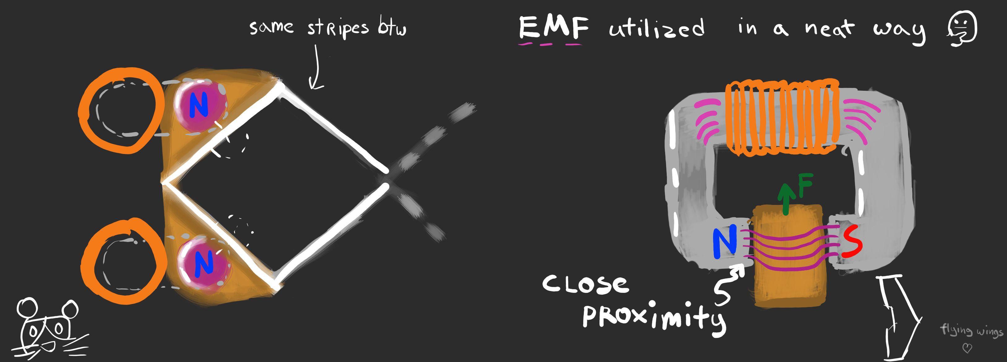 There, poles of an electromagnet are pretty close to poles of a permanent magnet (or steel bar), with that in mind it's closer to electromagnetic locks, while by trying to align magnets, it still has somewhat nice operating range.
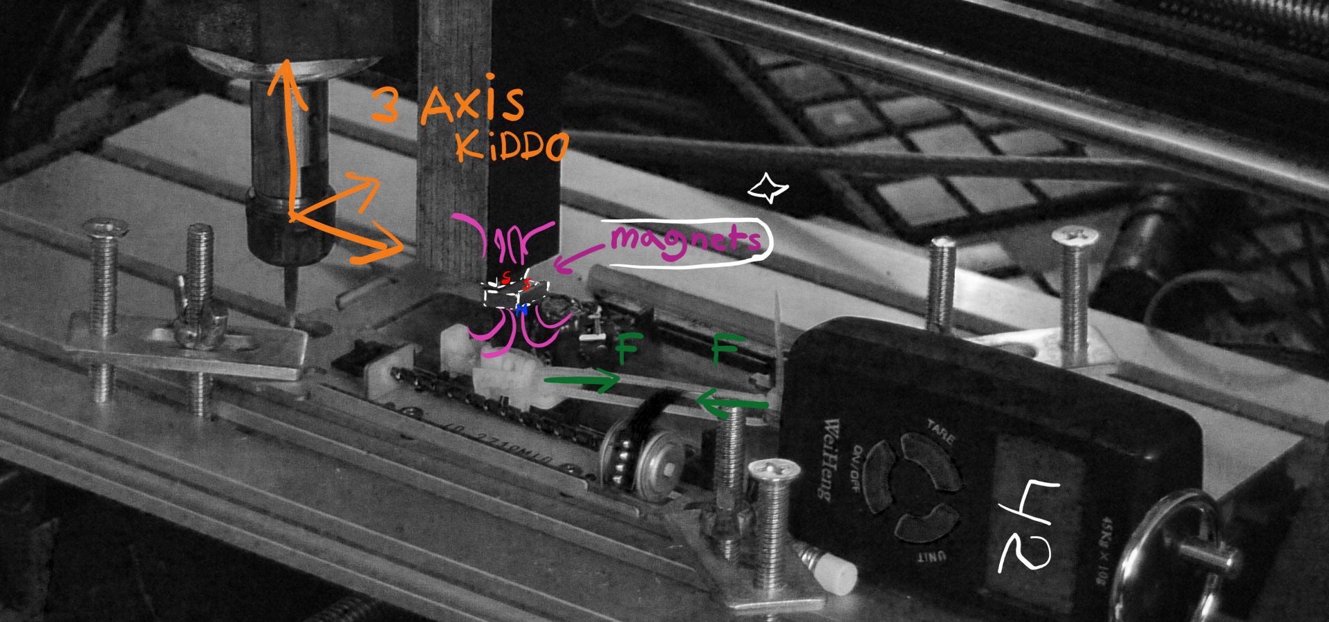 As I use parts from an old disk drive as a linear rail for magnet, it had a very noticeable friction. Also, linkage between scales and a moving magnet wasn't perfect, as it tended to be springy...
 As you can see, gap affects performance very much. I can make an educated guess that it would be full holding force with a gap shrinking to zero. That means that some tolerance in making artificial muscles, as it is for now, is needed to make them perform well
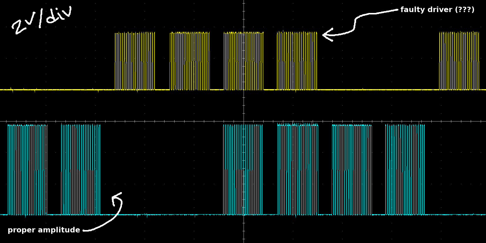 It never got sufficient voltage to fully open. I have no idea why one of sides died this time, or maybe it's components around or flux remained on a PCB? Hope I would find a reason. If not - I will make new PCB for trials with dip panels for drivers to change them without tedious unsoldering procedures.
  Designed to measure thrust generated by a propeller, for that purpose there is an electronic weight in place. Why thrust, you may ask? There is an interesting relationship between thrust and output power - it's perfectly linear. If that setup would generate more thrust with methods suggested before, it would mean that it is more effective, definitely. Even through it seems to work, it should help to get more convincing numbers, I'm not talking about power measured in watts, since it requires different rig, but in terms of how output power relates it does it's job.
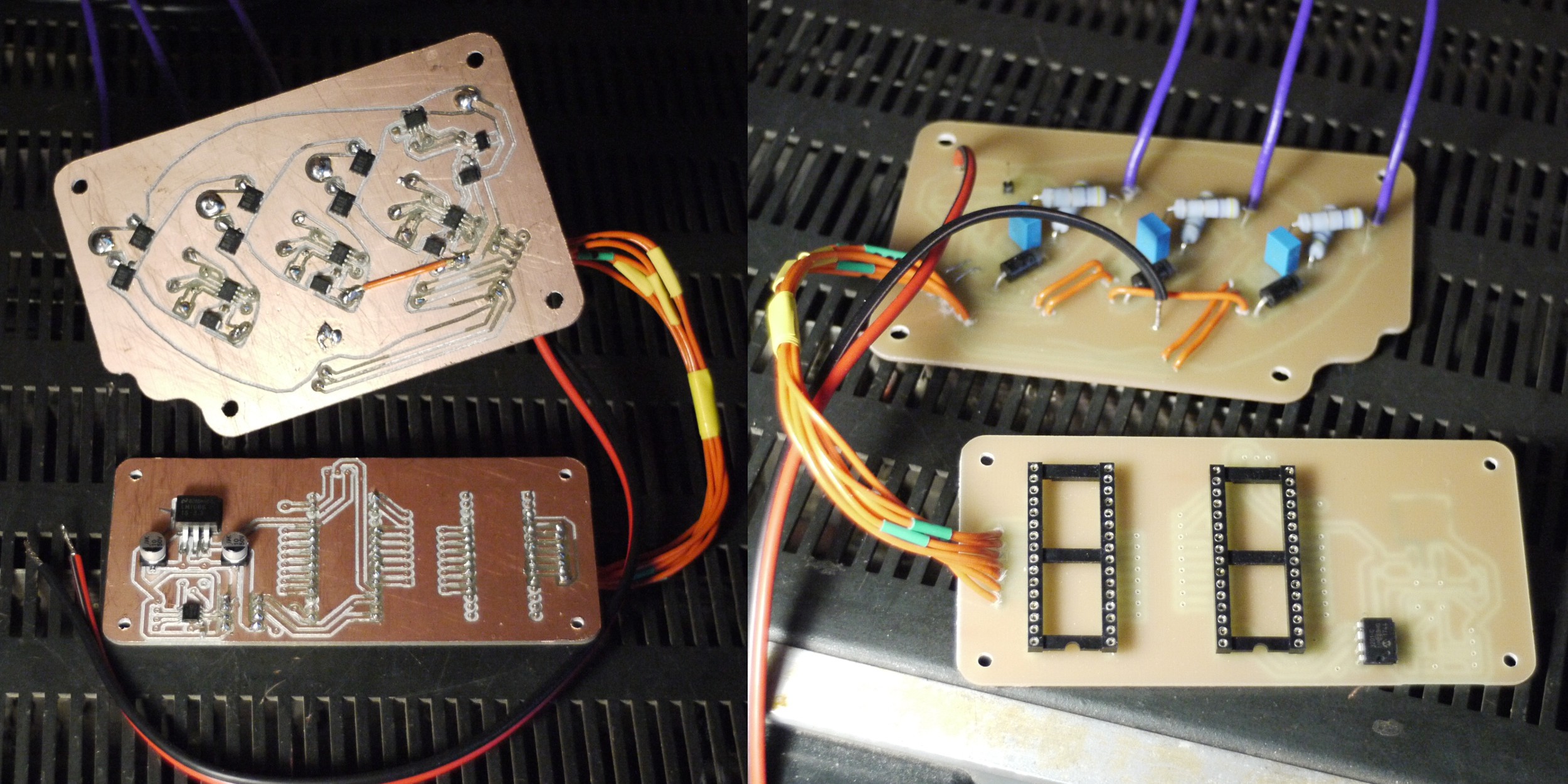 PCB at the bottom would serve as a measurement tool for testing bench, it has 12bit DAC and instrumental amplifier with adjustable gain to measure torque. More of that in next updates as there is some problems with that controller. It works, overall, but "rings" like crazy. Here is a photo with re-soldered FETs and voltage on transistor's gates:
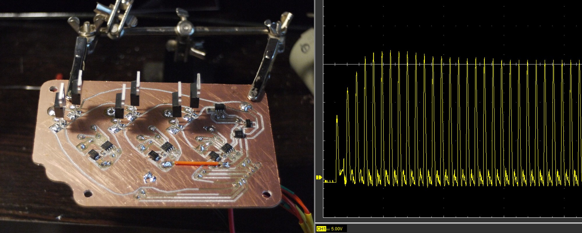 Looks suspicious! I don't know what's the reason for that. Maybe, protective zener diode cause some problems. But the fact is that even without motor connected it drains noticable current and produces sound. Sound which is normally produced by a great currents flowing through tiny components. It's not a norm : )
 Had lot of fun tracing that stuff! Aside of queer shape, it should have a damn good resistance and heat dissipation properties. Inductance should be less as well.
 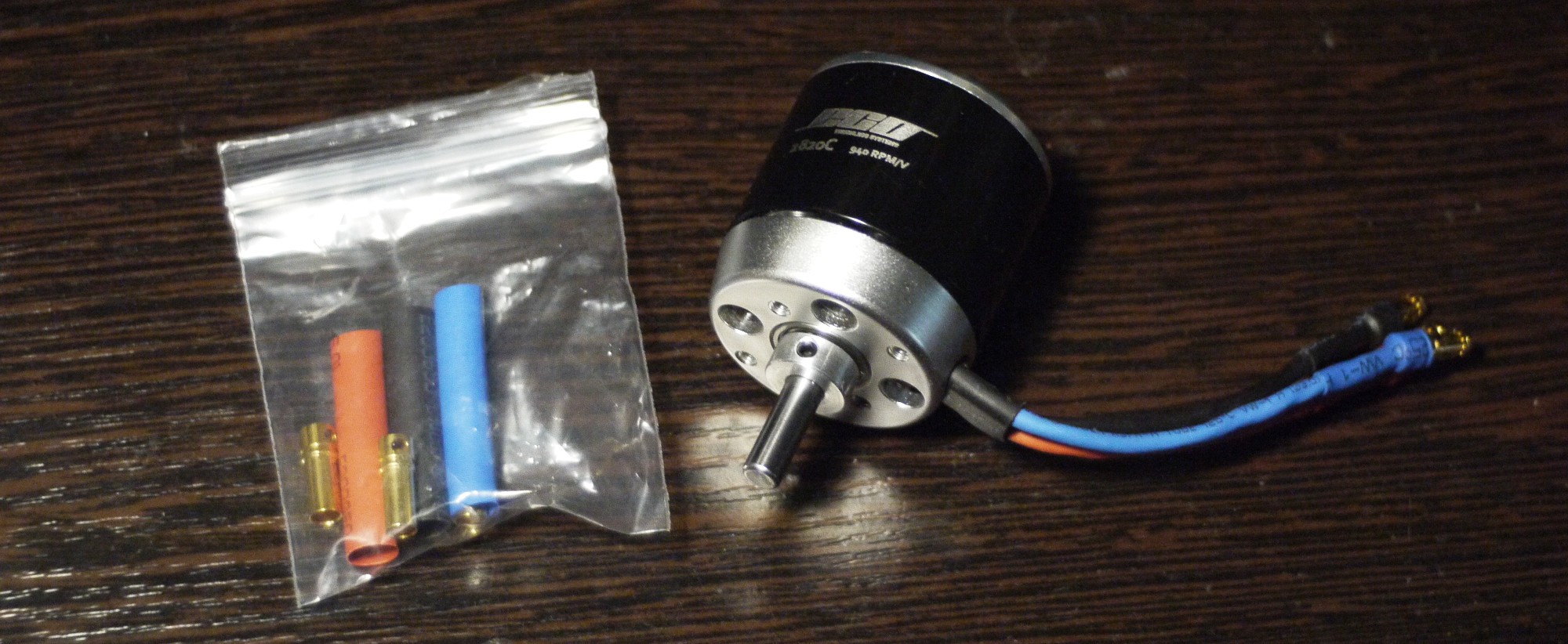 Motor has something around 30mOhm resistance, according to a manufacturer. Curious how it would play out, generally - low resistance would be a benefit, but with MCU-controlled board I'm pretty concerned about switching frequency. It's really easy to get sky-high currents that way x)
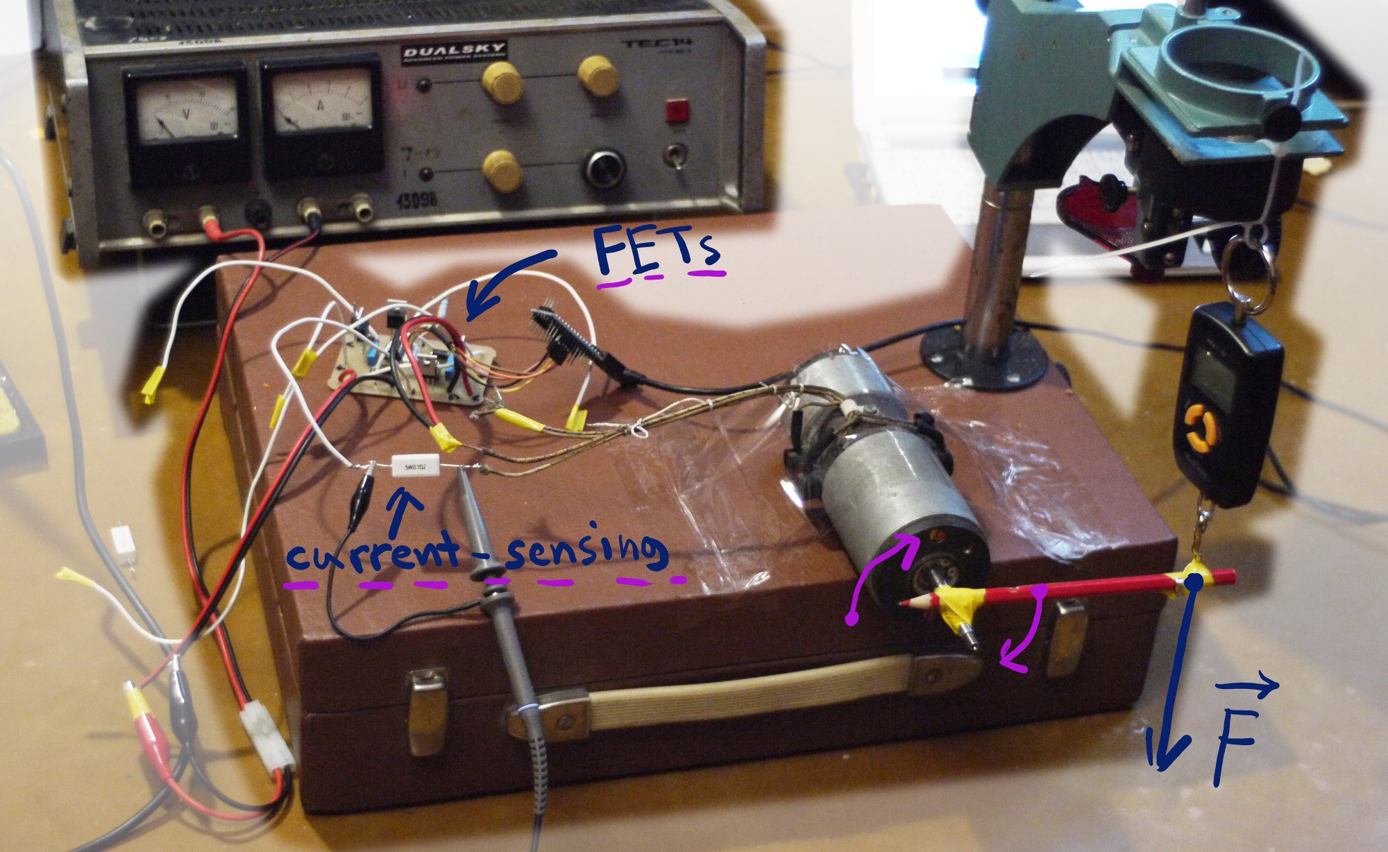 That photo magnifier was unused for years! But it came in handy, finally
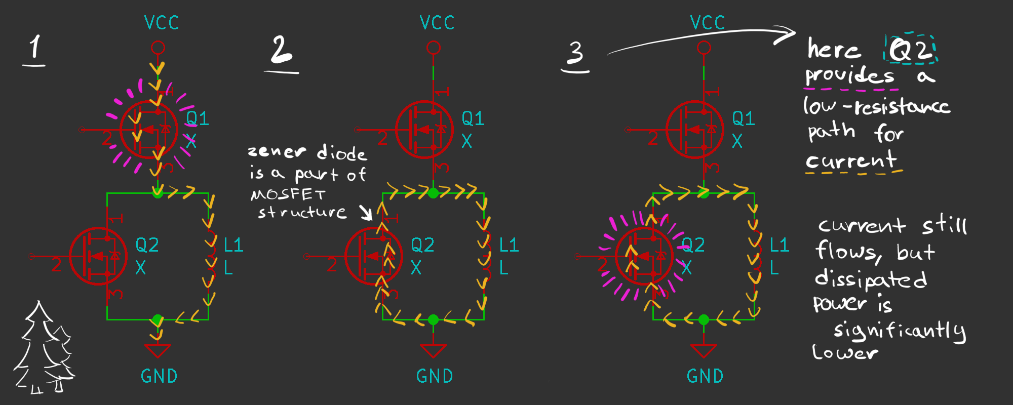 In theoretical Part 4 we came to a conclusion, what voltage drop affects discharge time significantly. Must-read, but simplified - coil tries to produce constant current while discharging and it's a very easy task if voltage drop is minimal. One approach is to use a diode, however, 0.4V is pretty high. And that is where MOSFETs come to play, acting as a low-resistance load.
 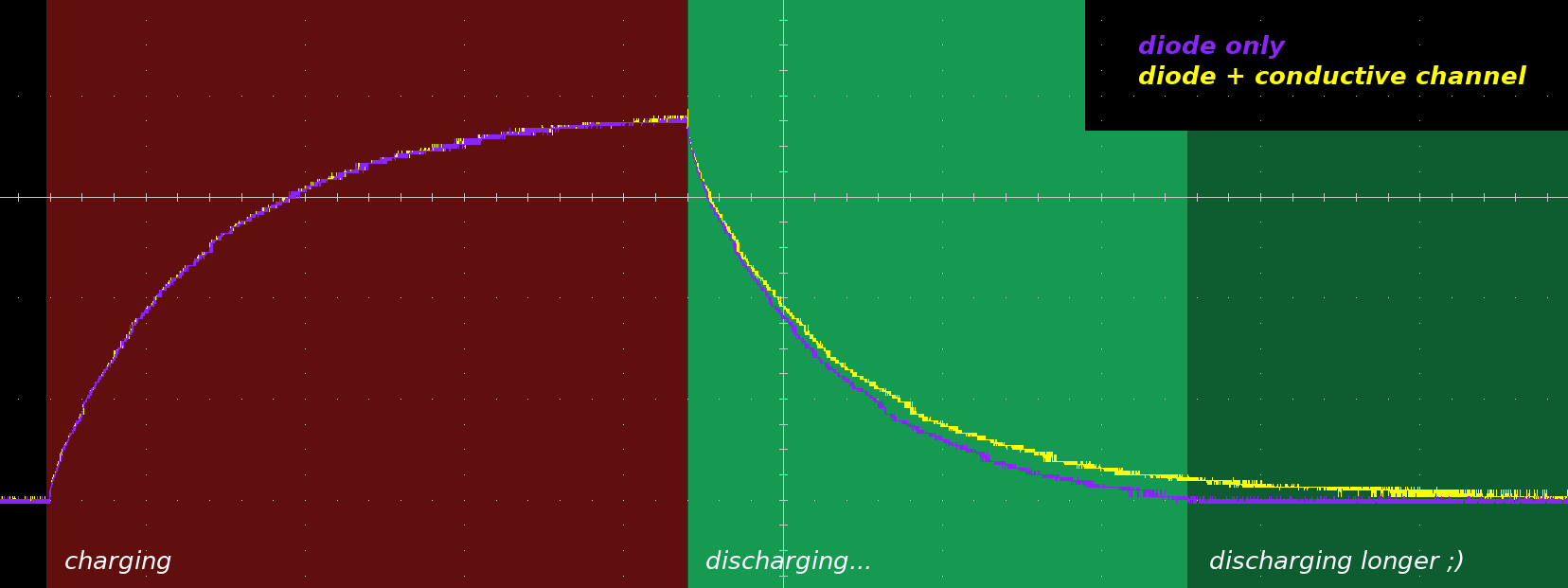 As you can see, it discharges about two times slower. It might be not very obvious, since discharging curve is really steep at the start, however, looking at the end of discharging process - advantage is pretty clear.