 CapitanVeshdoki
-
Discharge time and coils
12/24/2019 at 20:56 • 0 commentsIn previous update I said, that if fast charging of field is impossible for now, I gonna try to find a way how to slow down discharge rate. I found one, so here it is.
Interaction between a coil and a capacitor is kinda interesting one: coil itself tries to sustain current by any means and current is an amount of charge moving through wire each second, however energy needed to move one electron differs depending on your setup! It can be small, it can be large, and while you have limited amount of electromagnetic energy - it makes a difference.
For example, if you have 40J in a magnetic field and each electron takes 0.5J to move through your coil, you can move only 80 electrons in total, with current in mind it dictates coil discharge duration. Let's say, that we need to increase that. One way to do it is to use bulky coil (with greater inductance), with same current flowing it would have more energy, not a great option though - it will increase cost and make coil more inert. Second, neat way, is to tweak amount of energy each electron takes to move - this is where capacitors come to play.
First of all, where this energy comes from? It comes from voltage. Electron would move himself from negative (overpopulated by electrons) to positive (desert) side without need in external force, as it seeks lower energy state, but opposite is unnatural and some effort is needed. When you charge a capacitor - you move electrons in unnatural direction, where voltage is Q/C. Bigger capacitance means, that you can move more electrons without significant rise of voltage and therefore - less energy used to move same charge. That's how you can discharge same electromagnetic energy with same current longer and that's what we see in LC circuits, where period of oscillations is somewhat proportional to C.
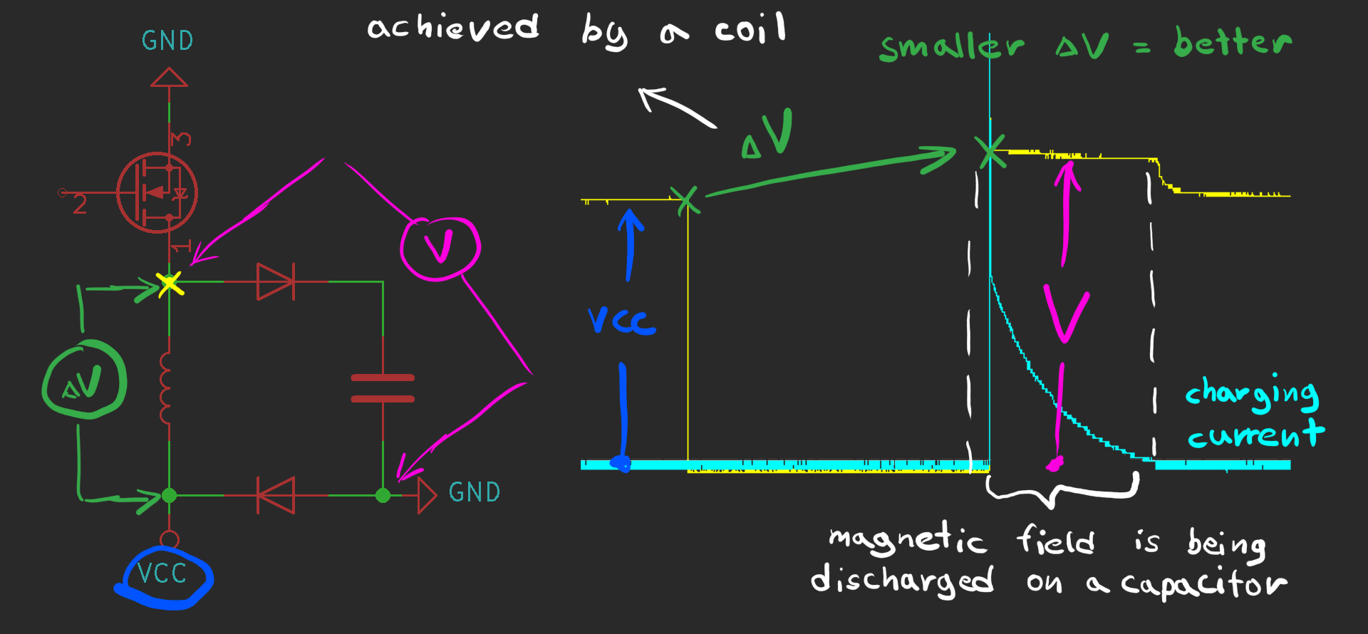
So... Can we simply increase capacitance? Of course we can, but there are much more elegant approach to that, which I found today! Let's nickname it... Battery-handled discharge.![]() What we can see there is pretty interesting. Ground and MOSFET at the top are used to charge coil. VCC is connected all the time, pre-charges capacitor to a power supply level. Right after ground is disconnected, coil charge capacitor and... does it in unusual manner! Electrons from capacitor's top plate are forced through coil, but not to the ground level - to the VCC level instead. It gives us really shallow potential difference (dV) and we win loooong discharge time! Other part of potential difference is handled by a power supply, while it tries to remain positive : )
What we can see there is pretty interesting. Ground and MOSFET at the top are used to charge coil. VCC is connected all the time, pre-charges capacitor to a power supply level. Right after ground is disconnected, coil charge capacitor and... does it in unusual manner! Electrons from capacitor's top plate are forced through coil, but not to the ground level - to the VCC level instead. It gives us really shallow potential difference (dV) and we win loooong discharge time! Other part of potential difference is handled by a power supply, while it tries to remain positive : )
Here you can see how energy needed to move charge (aka dV) affects discharge time:How effective it is? From previous theoretical updates: field charging process becomes very-very ineffective as it goes, so I tested it with a reduced charging time:
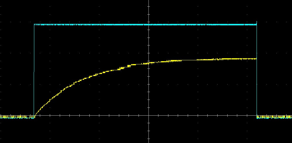
![]() As you can see, goal "discharge time > charge time" was achieved much more easily this way, without significant loss of current. And theoretically - there is a room for improvement!
As you can see, goal "discharge time > charge time" was achieved much more easily this way, without significant loss of current. And theoretically - there is a room for improvement!
Currently, there are only one limiting factor - voltage drop on a diode. That's a voltage drop, which cannot be defeated and great amounts of energy are wasted there, that limits discharge time. Maybe it's possible to replace it with another MOSFET, but I'm not sure for now.
And last thing - what about efficiency? Is it bad, that power supply handles something? Really, nothing to worry about! All that energy goes to charge a capacitor, so it can be reused, obviously. It's not something, what is dissipated in form of heat : )
P.S. Would be sweet to find a way to charge field faster, as I tried previously. But all that made me think: if slow discharge equals low voltage, doesn't that mean, that fast charge would always be a high voltage? Is it really possible to achieve it other way? -
Ouroboros healed itself!
12/23/2019 at 00:13 • 0 commentsHello everyone!
One month later I debunk my suggestion from a previous log, that electromagnetic field can be charged insanely fast using capacitors as a medium. Partly it taken so long because I played with a new desktop milling machine, partly because I was trying to combine my previous schematics with not working one![]()
This is how it ended:
![]() I checked current, after all! And I had no idea that something was wrong there, as I was totally sure, that voltage drop (mentioned in previous log) has something with current, but it seems... that my oscilloscope was calibrated badly. Even if all seemed pretty logical
I checked current, after all! And I had no idea that something was wrong there, as I was totally sure, that voltage drop (mentioned in previous log) has something with current, but it seems... that my oscilloscope was calibrated badly. Even if all seemed pretty logical
After 70 conducted experiments, using indirect clues, I finally found that something was off!
Checked, re-checked and here I am : )
What does it mean for project - is that it thrown back a few steps. Important ones - it's not so convenient now and with boosted charging process it could've been a completed one. It doesn't mean that we left without options, however: using high voltage is a really questionable stuff to do, as alternative we can slow down discharging process - and it is a good way to go. It doesn't really matter, what we use - fast charge or slow discharge. Capacity helps with that - well known fact. And it's probable to find some additional methods if we are lucky, who knows! -
Ouroboros is broken!
11/12/2019 at 17:36 • 0 comments![]() Ho ho ho! Here we go again! : )
Ho ho ho! Here we go again! : )
Do you remember my promise to come back if I would manage to develop charge-based electromagnet? Well, I failed with that, I can't solve this riddle, but... I have a mind-blowing alternative!
This would be a long story, so I am gonna describe what I achieved in couple of words for readers not familiar with electricity and then I'm gonna head towards details and sort of theoretical explanation.
Core problem of electromagnetic actuators (and all electromagnetic devices) is heating - it limits power/mass ratio and wastes precious energy onto something you don't generally need. In a situation when magnetic field isn't performing any work it's especially ridiculous.
In previous logs I noticed, that dissipation isn't an attribute of current in a several case, but this case cannot close the circle alone: it was true only during discharge of a magnetic field. Before that I discovered, that voltage at some extent can reduce dissipation and started to develop a control circuit, which can operate under high voltages. High voltage is a real trouble to deal with!
Briefly speaking, greater voltage can charge coil faster. But is it the only way to do that? No.
You can hack a resistance itself. Superconductivity allows you to get very strong fields, this method also does. Later it can be used for transformers, drone engines, precision machines (to minimize thermal expansion) and, of course, it makes my "artificial muscles" possible : )
Theoretical explanation and details
Previous theoretical parts:
Part one
Part two
1. Possible source of heat dissipation
As we found, you can get current without a heat, traditional "frictional" explanation doesn't seem so fair. We know what voltage can be a result of a potential difference and "potential difference" redefined - difference in energies. Electrons flow from greater potential (-) to a lower potential (+)
So... Energy drops! And where it goes? Maybe into heat. P=U*I, where U is energetic difference and I is amount of charge, which goes through that difference every second. Similarly, E = U*I*t, where I*t is an amount of charges which went through that difference overall.Let's consider three situations:
![]() First one is a typical situation with a resistance, voltage drop on which represents potential difference.
First one is a typical situation with a resistance, voltage drop on which represents potential difference.
Second one is a discharge of a capacitor onto coil, where potential difference produced by a capacitor.
Third one is interesting one, as coil never takes voltage into account, only current, it would try to produce enough voltage to maintain flow of electrons, so voltage on a coil stays equal to voltage on a capacitor. There are still a lot of questions about this one, but it's the one with virtually no heating at all.
> > > > > > Disclaimer! Next part is a wrong assumption! Left it there just for history : )
2. Boosting a field-charging process
To generate electromagnetic field we should achieve surface charge gradient (according to a first theoretical part) and it seems that this gradient is tightly bounded with current & voltage. But as we have a "perfect" discharging cycle which takes some time (this was in a second theoretical part), we can try to speed-up charging process that much, what it wouldn't dissipate much energy and efficiency would be close to 100%.
There are two ways how we can move charges - non-insulated way, like we always do by attachment of power supply or a capacitor and external field way - insulated. Best way to generate external field is by a capacitor. Fun part - external fields never bothered by internal circumstances! And resistance is one of that circumstances. That's how we swap resistances here!
![]() Elegant, easy, all our problems with charging solved. Experimental setup was also simple:
Elegant, easy, all our problems with charging solved. Experimental setup was also simple:![]() Relay was needed to connect VCC and GND simple way, without P-channel MOSFETS or high side drivers for them. It added some rattle in oscilloscope data though:
Relay was needed to connect VCC and GND simple way, without P-channel MOSFETS or high side drivers for them. It added some rattle in oscilloscope data though:![]() Significant improvement. Voltage drop on external circuit resistance is very helpful, since we can determine when current is on the right level and when charging process ended. If curious - this electromagnet charges for about 16ms attached to a power supply, 40x times slower than here!
Significant improvement. Voltage drop on external circuit resistance is very helpful, since we can determine when current is on the right level and when charging process ended. If curious - this electromagnet charges for about 16ms attached to a power supply, 40x times slower than here!
I simulated this process using methods from first theoretical part, worked just fine:![]() As a conclusion: resistance swap rules! : ) {actually - not, ahaha}
As a conclusion: resistance swap rules! : ) {actually - not, ahaha} -
Control circuit V2
10/15/2019 at 21:18 • 0 commentsHello everyone! Again : )
Previously I figured out how to achieve a real efficiency gain, v1.2 circuit board had various limitations, as well as a few mistakes. Summer ended, now I have less time for my own projects, but I gain experience developing other stuff and I can implement it here!
I reconsidered some aspects of a board, and that is what I have now:![]() This time I chose distributor of electronic components who works internationally instead of our local shop, so I had a wider range of components to choose from! What's why now board features automotive connectors for example, way better than "PC" connectors stocked in our shops : )
This time I chose distributor of electronic components who works internationally instead of our local shop, so I had a wider range of components to choose from! What's why now board features automotive connectors for example, way better than "PC" connectors stocked in our shops : )
I added a DAC, sending PWM signal from MCU constantly isn't reliable at all, as well it gets affected by inductance of wires coming to a control circuit, e.t.c. e.t.c. Instead of that, we can use SPI, to connect great amount of independent boards. And I'm not choosing I2C, 3bit addresses for individual DAC's cannot give enough freedom if you're willing to connect 30 board at some point.
As this iteration is suited to work with high voltages (300V max), optocouples are necessary to protect MCU, which can be quite expensive. I have high-side driver this time, it wouldn't dangle on wires somewhere aside of a board. Last time it confused me much, now I tuned this thing nicely and it should work well. Finally, you may notice test points - they should be very helpful for maintenance.![]() Overall, design is much more robust now, can't wait to see it working, I have plans for that one. Now it should cope with power needed to my linear actuators and I really want to experiment with transformers and BLDC motors, this board is suitable for them too, as it is a general-purpose EM field controller.
Overall, design is much more robust now, can't wait to see it working, I have plans for that one. Now it should cope with power needed to my linear actuators and I really want to experiment with transformers and BLDC motors, this board is suitable for them too, as it is a general-purpose EM field controller.
Bringing down heat dissipation of a conventional BLDCs gonna be fun :D
P.S. PCB ships for about 30 days, components... I think they have same delivery time, so next update should be in December. Time passes by so fast! However, do you remember concept of charge-based electromagnet from previous log? It seems that I figured out how it possibly can be done, if it works, next update is much closer than December and it would be amazing. Why? Hm... ) -
Studying energy dissipation
09/24/2019 at 17:54 • 0 commentsI advise reading previous update ("Bye, DC!"), it's a crucial part - it contains important ideas about power & energy in electric circuits, revealing phenomenon of inductance and resistance on a new level - now it's my instrument of choice for working with electromagnetic processes.
Hello everyone! Again : )
Previously, I described a proportion, in which power allocates between charging electromagnetic field and heating a conductor and it was a bit of a shock for me, originally I wondered, how we can eliminate heat dissipation completely. Now it seems impossible? Not quite!
I see two ways, how to come round that heating misconception:
1) We can develop a new sort of electromagnets! If we assume, that proper distribution of charge in space (and not specifically in a conductor) creates a magnetic field, that means, that we can recreate it similarly to a capacitor. It would be a charge-dependant electromagnet, which can store electromagnetic energy as long, as charges present in it. In a traditional coil waste of power dictated by a unstable state of charges, covering a conductor - you need to apply external "force" to prevent "positive and negative charges" from collapsing, that's why applying voltage is an essential thing there. However, I failed to notice any sort of a magnetic field around flat capacitor. It doesn't mean, that it's 100% not there - it's probable, that Earth's magnetic field outruns weak field of a capacitor - it requires more studying. If I would get an idea how to make such a thing - I would share it here. It would be epic, if it's possible ; )
2) We can exploit an interesting behaviour of a traditional coils. More on that in next part:
Exploiting physics:
Even an energy dissipation law has it's own backdoor! And this backdoor is a fact, that if you apply no power to a conductor and retrieve most of energy, that it gives to you, it's not likely to dissipate something into the air. Current might stay the same, who cares!
I made some measurements:![]() I submerged my electromagnet into a vessel with water and powered it up, recording changes in temperature. It takes about an hour to temperature to drop down for a 2 degrees in this setup, as it features some thermal insulation after all, water volume stayed untouched
I submerged my electromagnet into a vessel with water and powered it up, recording changes in temperature. It takes about an hour to temperature to drop down for a 2 degrees in this setup, as it features some thermal insulation after all, water volume stayed untouched
Here are results:![]() Control circuit changed situation a lot - reducing energy dissipation for about 30%
Control circuit changed situation a lot - reducing energy dissipation for about 30%
On the right side you can see oscilloscope date, isn't it looks familiar? :)
That then, 30% is our upper limit? Not at all! Retention of energy goes on a constant rate independently of a charging rate, as it is a typical LC oscillatory circuit. We can use it in our favour, increasing charging speed. Here are few samples with another electromagnet:![]() Using higher voltage, we get great charging:retention proportion, also - increase in a field-charging efficiency, according to a model presented in a previous update.
Using higher voltage, we get great charging:retention proportion, also - increase in a field-charging efficiency, according to a model presented in a previous update.
Conclusion:
Increasing retention time looks like a solution, can it be done by increasing capacity?
Who knows! Time will show!
Is it possible now to pump 300W into a electromagnet without burning it down?
Theoretically - yes. But new version of a control circuit is needed.
That one isn't suited to withstand such voltages & currents yet.
Can we use these methods with BLDCs and stepper motors?
Sure! With everything that has coils.
It seems, that this project requires more time to finish. But it's so much fun!
Then I started it, I never imagined, how many things gonna be uncovered.
Stay tuned! I surely would finish it... Somewhere... ) -
Bye, DC!
09/03/2019 at 14:30 • 0 commentsThis log would be very strange, I wanna introduce new physic theory
Well, I tried to stop myself from doing that kind of work, kept saying "Just use that, don't trash your head with such an outrageous things, you have a lot of another stuff to do" - and here I am!
Now, I want to list, what I don't like in conventional conception of electrical engineering:
- If dissipated power is really U*I (according to Joule's Law), why then it's possible to perform any kind of work? To generate a field, which has energy, you should take that energy from somewhere, as we say that U*I equation is right 100% of time - it should be impossible, however, transformers, oscillatory circuits and electric motors have no problem with it.
- If we say, that coil has an energy of field proportional to flowing current (L*I^2/2), then how on Earth it starts to charge? Traditional chicken & egg question. If we say, that there is no power without a current and no current without an energy...
Needless to say, that traditional laws of physics had no chance to uncover the mystery how my circuit really works even partly. And I was OK with that, until I found efficiency problems in my design and tried to find a reason.
I'm not pretending on universal truth and I have no intention to convince someone, but this theory explains electromagnetic processes much better, in my view, makes a lot of things clearer than ever.
I want to start with a little bit of description, what is the origin of a stable current in the conductor. It's an experimentally proven (but probably not widely-known) fact: distribution of charge on the surface of the conductor.![]() And it's fair to say, that as we have potential difference, we have potential energy between charged particles at least. Then I thought about reasons why my circuit is not as effective as needed, it was the first thing which came onto my mind: as I have diodes, it must be a tough work for magnetic field, to power up electric field and break through potential barrier!
And it's fair to say, that as we have potential difference, we have potential energy between charged particles at least. Then I thought about reasons why my circuit is not as effective as needed, it was the first thing which came onto my mind: as I have diodes, it must be a tough work for magnetic field, to power up electric field and break through potential barrier!![]() Idea of two energies on the surface of a conductor was very catchy and since that time I started thinking about it, as it seemed, that that charge is responsible not only for current, but for magnetic field, inductance and... resistance! Typically, we say, that we have two types of resistance: resistance and electrical reactance, probably it's an artificial division, caused by urge of numerical description and lack of understanding. That was OK for a typical AC applications, but not enough now, then we are talking about behaviour of an electromagnetic field. Let's have a look:
Idea of two energies on the surface of a conductor was very catchy and since that time I started thinking about it, as it seemed, that that charge is responsible not only for current, but for magnetic field, inductance and... resistance! Typically, we say, that we have two types of resistance: resistance and electrical reactance, probably it's an artificial division, caused by urge of numerical description and lack of understanding. That was OK for a typical AC applications, but not enough now, then we are talking about behaviour of an electromagnetic field. Let's have a look:![]() I wouldn't comment that a lot, as imagination is more important here. With same applied voltage, conductor with bigger section area have greater electric flux, and current raises proportional to R^2. On the other hand, electrical resistivity defines surface density of charge for a specific applied voltage, not a conventional "friction"
I wouldn't comment that a lot, as imagination is more important here. With same applied voltage, conductor with bigger section area have greater electric flux, and current raises proportional to R^2. On the other hand, electrical resistivity defines surface density of charge for a specific applied voltage, not a conventional "friction"
So every conductor has that properties. Difference is only how much "inductance" and "resistance" it has. Important to say, that potential energy between charged particle and energy of magnetic field are tied together. There is no magnetic-field energy without proper electric-field energy and vice versa! For example: then you wrap wire around a steel rode, you add an object, which your wire needs to magnetize - it's harder now to cover a conductor with electrons and generate current, each potential difference there "costs" a part of magnetization process.
Funny enough - there is even an interesting relation between temperature and energy, which you need to pump in. For some reason, potential energy between charges decreases with lower temperatures and conductor can gain more electrons proportional to that. I found that, then efficiency of my circuit increased as I put electromagnet in fridge. I think, same process takes place in superconductors (more pronounced) and in batteries at cold - amount of charge stays the same, energy decreases, there is no chemical explanation for now, as I know, so I can give it a try :)
Well then, that about power? There that energies take Joules?
I questioned myself a lot about power dissipated in form on heat. And what if.... Dissipated power is an echo of power, which charged our electromagnetic fields initially? Proportional to applied voltage? Dependent from resistance?
And it's likely, that this power is not only an echo, it slowly transits from charging the fields to dissipating heat, but summary remains constant! Potential difference grows, while conductor is being charged. That's why, if you had initially Up (voltage of a power supply) about 10V and Uc (voltage on a conductor) about 0V, in the end you have no charging going on.
Power distributes like this:
- (Up - Uc)/Up part goes into energy of fields
- remaining part just dissipates in form of heat
- then Up = Uc, all power is being dissipated in form of heat
All that leads us to ridiculously clear understanding of a process and even more ridiculous simulation with simplest math:![]() Most amazing, that you can weight roughly how a lot of things work with understanding of that.
Most amazing, that you can weight roughly how a lot of things work with understanding of that.
You can predict efficiency of electromagnetic devices
You can design them in the most efficient way easily
And that I like the most - my circuit is not a black box for me now ; )
At the end I want to give some examples, how to work with it:
1) We have a transformer, how to use it efficiently? Let's see, at first - it's a simple coil with a core. Obviously, as only (Up-Uc)/Up part goes into energy of a magnetic field, we would want to keep Uc as distant from Up as we can.
If our line is 220V 50Hz and our target current is 5A, it would be logical to make a 4 Ohms primary coil with proper inductance to let the current rise up to 5A, but to keep it away from 78A current maximum. Using graph on the right side, we can predict efficiency around 95%. 5/78*100 = 6.4, then look for intersection:![]()
2) Same thing goes to electric motors - we don't want them to reach their maximum current capacity, that's why we would try to choose coil uptimes according to that. And that is the reason, why on low RPM (for which they are not designed) they heat so much, especially stalled, then efficiency is 0%
Hope, it was interesting to read , ) -
log(22)
08/22/2019 at 14:46 • 0 commentsHello everyone! I try not to miss my train, so this log gonna be short. : )
Just want to write a little about experience I had with magnetic locks, which I bought yesterday:![]() First of all, their efficiency isn't that great as I expected, for example, 60kg of pulling force doesn't mean, that they make field equivalent to a 60kg permanent magnet, because distribution of magnetic lines is different, so in stock (with 4W of power) they cannot mimic rare-earth ones, however, with this setup I pumped in around 300W of power, and it was enough. Now I know, that it's a working concept.
First of all, their efficiency isn't that great as I expected, for example, 60kg of pulling force doesn't mean, that they make field equivalent to a 60kg permanent magnet, because distribution of magnetic lines is different, so in stock (with 4W of power) they cannot mimic rare-earth ones, however, with this setup I pumped in around 300W of power, and it was enough. Now I know, that it's a working concept.
However, if we talk about traditional way of powering electromagnets up, 300W of heat dissipation underlies there and it's a crazy amount of heat! In other words, even if we forget about power consumption, we have no way of making so energy-dense electromagnets without that interesting control board, which (hooray!) I already developed and have on my hands.
And it looks like I found a reason, why efficiency changes so much through changing of PSU voltage, there was one stupid mistake I made, I would write a long log on this subject, it should break previous 75% efficiency barrier , ) -
100% ready, 70%+ efficient
08/12/2019 at 20:05 • 0 commentsI wasn't there for a while, however I have some amazing news now!
After 1 month of struggling, after a month of trying different complicated electromagnetic structures, I finally found electromagnet (which was lying on my table for 4 years for now and was a part of various experiments with control board) nice enough to try out something with them.
As I told in previous post, I wanna utilize magnetic field better, then... here we go!![]() Looks evident? Well, it wasn't evident for me, even if I knew, what magnet (which I have) produces same attraction force, as a reference permanent magnet. I thought, that field shape isn't proper for this use. Today, experiment shown, that there is nothing bad with it at all, silly me!
Looks evident? Well, it wasn't evident for me, even if I knew, what magnet (which I have) produces same attraction force, as a reference permanent magnet. I thought, that field shape isn't proper for this use. Today, experiment shown, that there is nothing bad with it at all, silly me!
And there is even a magnet with desired shape on a market!![]() Yeah, that is a magnetic lock )
Yeah, that is a magnetic lock )
Widely-available thing. Also can be hand-crafted, but it's not the point right now. Is it bad? Not at all! With it, our muscle supposedly can achieve 1.2kg contraction force with only 3W power consumption + work performed by muscle (in other words, by a magnetic field)
What we have now?
- fully-working control board, which saves 70%+ of energy for now, nice
- fully-developed stripe production process, pretty convenient
- electromagnets to power up everything!
What remains to do to build first working prototype?
Well, nothing! Except of urge to buy some magnetic locks
Stay tuned ; ) -
log(20) Fire works
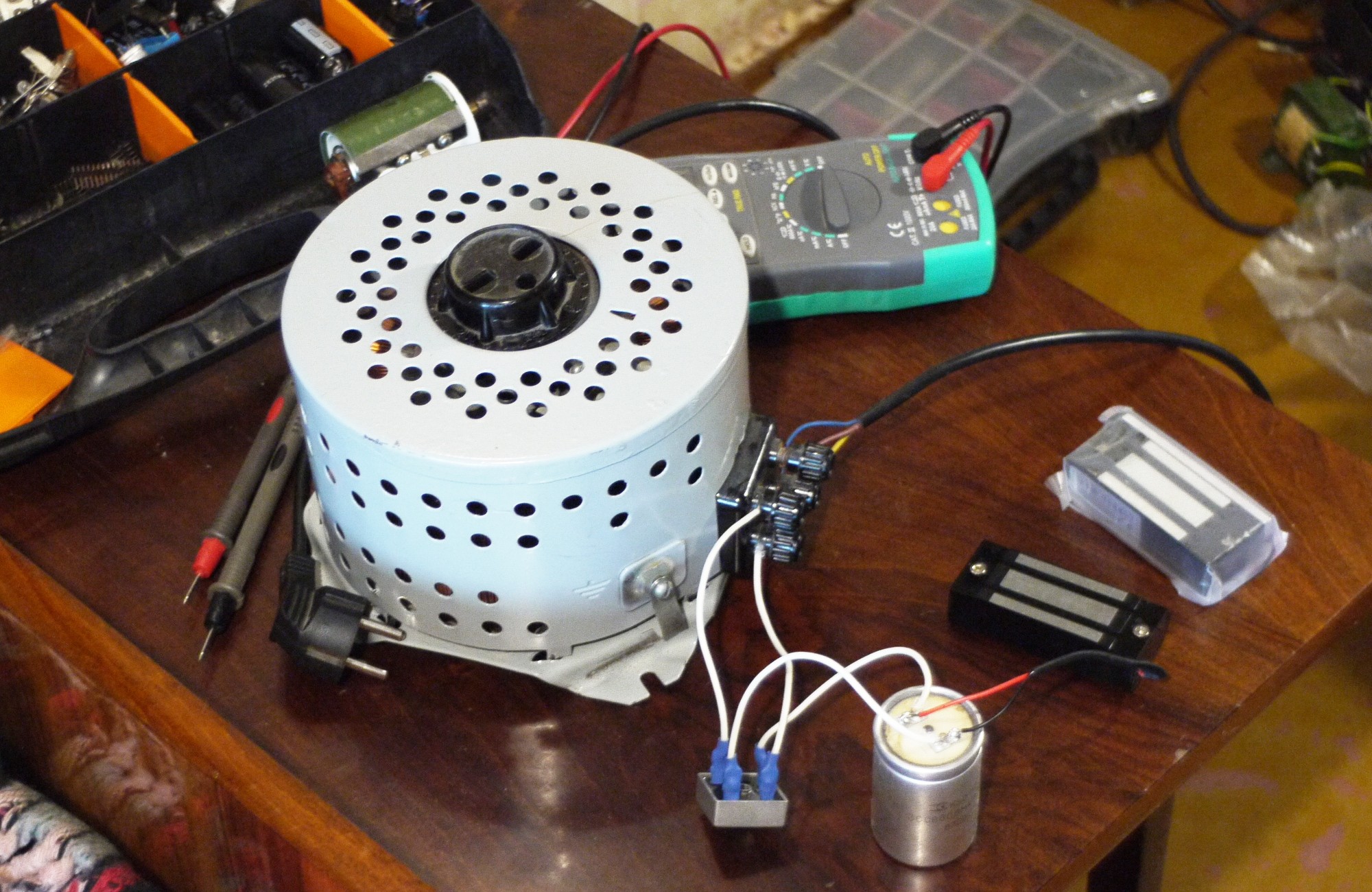
08/01/2019 at 11:30 • 0 commentsThis time I faced with another sort of problem. I've decided to install smaller capacitor to check if it has anything to do with efficiency, I was interested to get significant voltage increase on capacitor during charging cycle, and I've got it ;D
![]() Energy goes from coil to a capacitor and in some cases, then energy oscillation is quite noticeable, it charges capacitor too much, voltage raises and does some bad stuff to LM7805 stabilizer, which powers comparator and logic gates. Couple milliseconds and they are on fire! Beautiful sight )
Energy goes from coil to a capacitor and in some cases, then energy oscillation is quite noticeable, it charges capacitor too much, voltage raises and does some bad stuff to LM7805 stabilizer, which powers comparator and logic gates. Couple milliseconds and they are on fire! Beautiful sight )
My board has an option to connect logic-power (typically 14V, to power up MOSFET driver) and power-power (typically 21V and more) independently, so, you may ask... Why I'm burning components instead of doing that? Simple - I have only one PSU now. There is another 0-200V/5A on the horizon, based on compensator, I would use it in future, probably.
Since last post I rescued control board couple times. Also I found, that overall inductance (as a capability of storing magnetic energy) is meaningful to efficiency, it just becomes a radio transmitter with small inductance (working onto 14 MHz frequencies)
Also, I wasn't able to get efficiency higher than 75-80% on steel cores even with amazing coil of an industrial-grade solenoids. I tried ferrite core and got nothing from that too, but as I told - there wasn't enough inductance, so it's probable, that on more complicated winding it would work well, since ferrite isn't as conductive as steel.
What I'm gonna do next? Well, it's an end of summer, I have no intention to skip this wonderful season, also I work onto another project, commercial one, so I have less time to work onto this one, sadly
However, I have an intention to make my work easier: in this month I want to find more efficient way to utilize magnetic field produced by an electromagnet, instead of making that hardcore pure-Fe production line, this would make technology more convenient to replicate, it is already convenient in all aspects, excluding electromagnet production, it's a nice target , ) -
Quite interesting update
07/14/2019 at 21:59 • 0 commentsWell, lazy me soldered high side MOSFET driver yesterday, in replace of strange IR2117 (probably, burned)
![]() Now it use three transistors instead of IC, it gives bug-fix freedom. Happily, it worked "right from the box", transistor opens as needed, as bootstrap capacitor sends needed amount of voltage to drain.
Now it use three transistors instead of IC, it gives bug-fix freedom. Happily, it worked "right from the box", transistor opens as needed, as bootstrap capacitor sends needed amount of voltage to drain.
Yes, I cannot feel any heat, so I would return to surface-mount housings instead of heavy-lifters like TO-247 (however I like them, ahaha) - but it's not the interesting part!
Interesting part!Now I have fully-working electromagnet driver, and I've made some test. Results were kind of intriguing. First of all, I found, that you can maintain semi-constant current on coil, it wouldn't affect efficiency.
![]() As you can see, current is quite stable. I'm not sure if I can achieve greater efficiency by increasing amount of withdrawn energy. So we can forget about kind of PWMed magnetic field! Hooray!
As you can see, current is quite stable. I'm not sure if I can achieve greater efficiency by increasing amount of withdrawn energy. So we can forget about kind of PWMed magnetic field! Hooray!
But question of efficiency remains unsolved for now:![]() Gone wild! For some reason, supply voltage (and temperature!) affects it very much.
Gone wild! For some reason, supply voltage (and temperature!) affects it very much.
Yes, I tried to put electromagnet in a refrigerator : )
Temperature can influence resistance, however U^2/R equation (which probably not works in this case anyway, for many reasons) shows increase in dissipated energy as R decreases. So it's not the case.
For curious - I found 30% increase in efficiency within 20 degrees Celsius, impressing!
Most logical explanation which I found - that at lower temperatures core demagnetizes slower, as wobbling of atoms drops and it's easier to maintain them orientated, as well as their fields.
Sound earnestly and simple, however physics behind might be more complicated (as usual)
And it seems that it requires quite steep signal slopes while pumping energy in. Why?
Ahaha, I don't know why for now! All heat dissipation physics in electronics is quite strange and describes "simple" cases only, like stable current flows. Everything is different there: we work with unstable current - it's benefit and a punishment also - pioneering never been easy.
70%+ efficiency isn't a bad result anyway, with better understanding of heat dissipation process we can make everything better, high-energy fields without overheating possible, "dense" electromagnets with awful core material as well. But it's quite hardcore and I don't know how long it would take for me to complete such an thought experiment : )
So, I cannot escape need to make some pure-Fe cores, if you remember - actuators worked nicely on tests with rare-earth magnets, but making electric clone of them emerged into lots of problems to solve
linear actuations for everyone!
cheap artificial pseudo-muscles here
 What we can see there is pretty interesting. Ground and MOSFET at the top are used to charge coil. VCC is connected all the time, pre-charges capacitor to a power supply level. Right after ground is disconnected, coil charge capacitor and... does it in unusual manner! Electrons from capacitor's top plate are forced through coil, but not to the ground level - to the VCC level instead. It gives us really shallow potential difference (dV) and we win loooong discharge time! Other part of potential difference is handled by a power supply, while it tries to remain positive : )
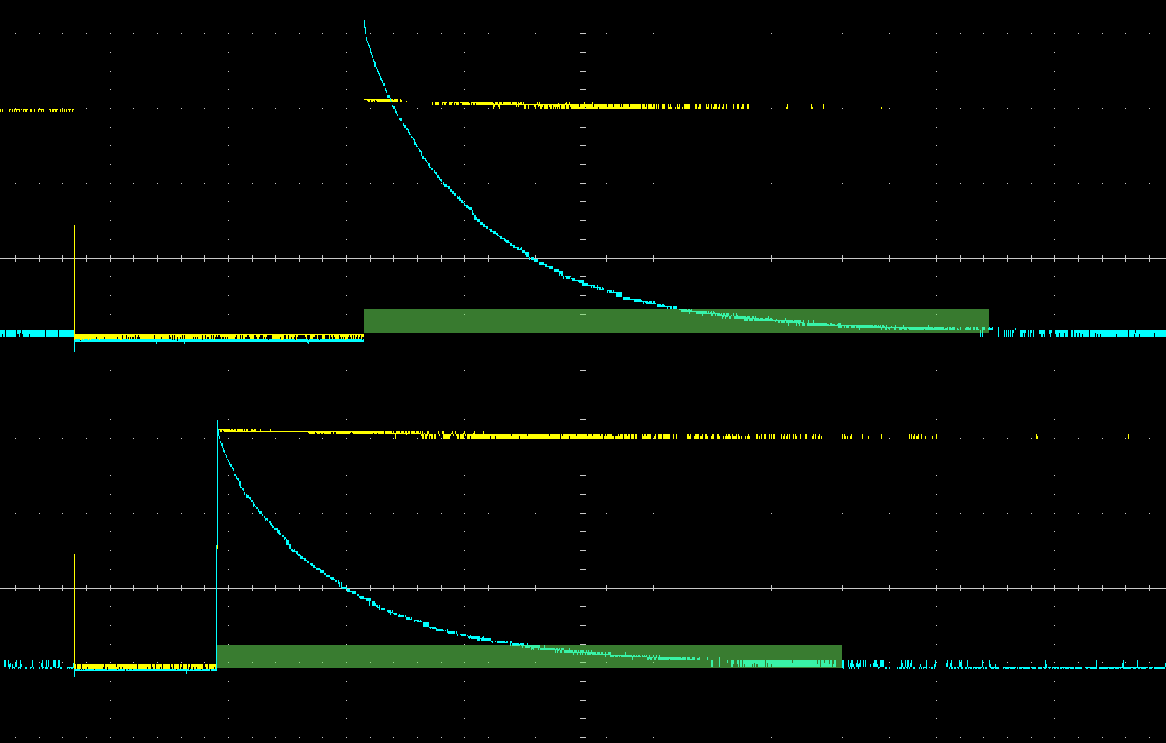 As you can see, goal "discharge time > charge time" was achieved much more easily this way, without significant loss of current. And theoretically - there is a room for improvement!
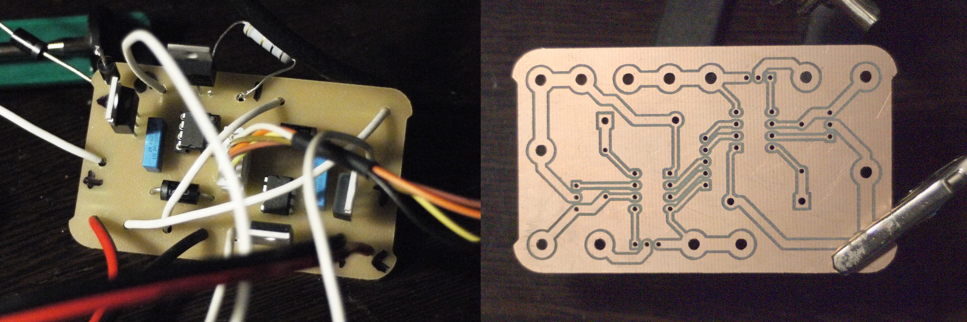
 I checked current, after all! And I had no idea that something was wrong there, as I was totally sure, that voltage drop (mentioned in previous log) has something with current, but it seems... that my oscilloscope was calibrated badly. Even if all seemed pretty logical
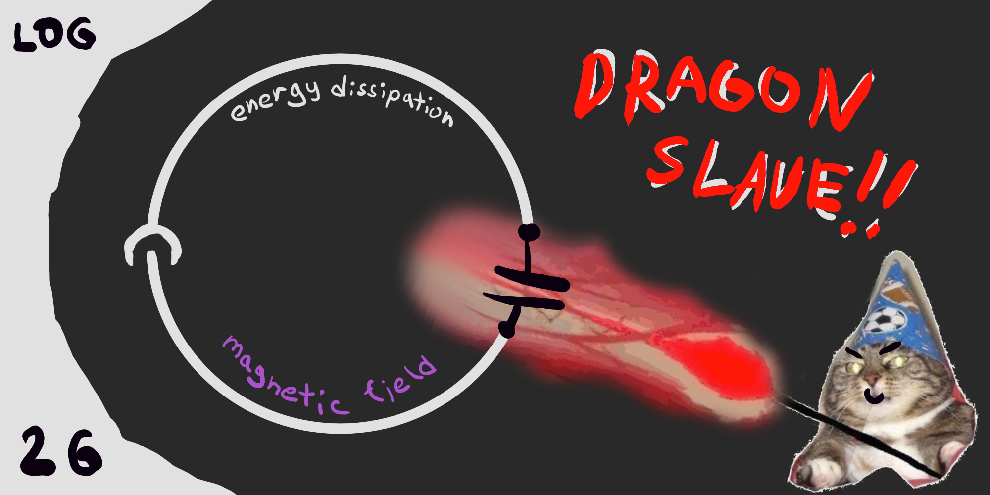 Ho ho ho! Here we go again! : )
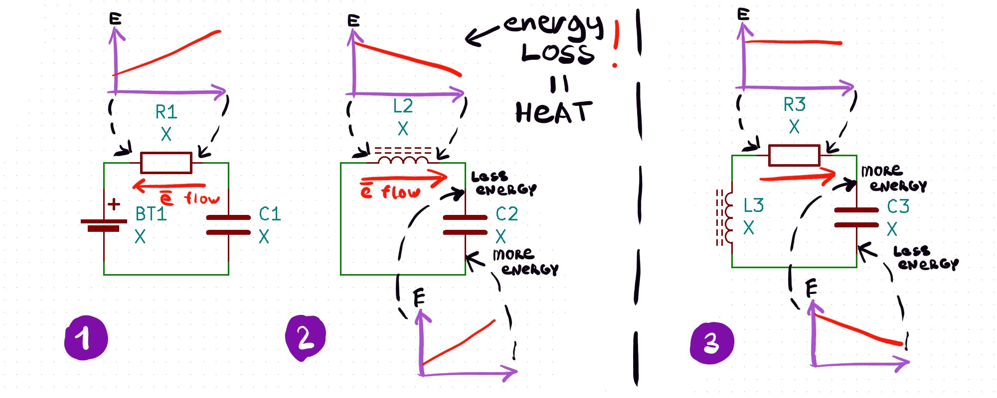 First one is a typical situation with a resistance, voltage drop on which represents potential difference.
 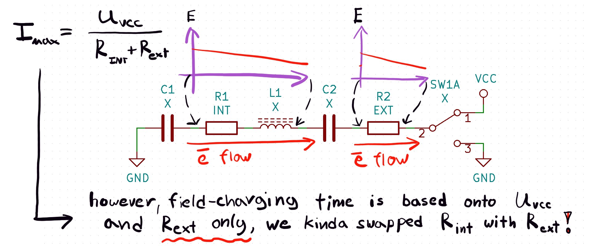 Elegant, easy, all our problems with charging solved. Experimental setup was also simple:
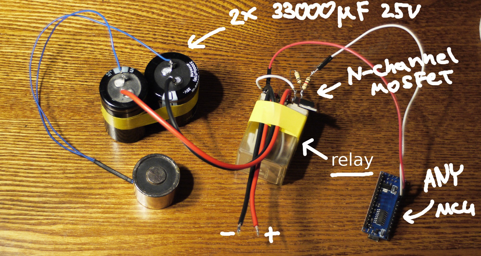 Relay was needed to connect VCC and GND simple way, without P-channel MOSFETS or high side drivers for them. It added some rattle in oscilloscope data though:
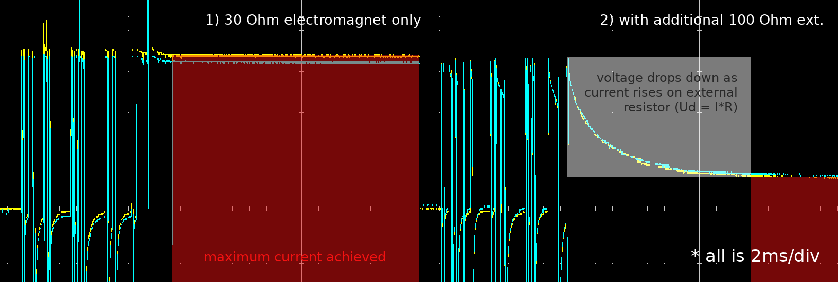 Significant improvement. Voltage drop on external circuit resistance is very helpful, since we can determine when current is on the right level and when charging process ended. If curious - this electromagnet charges for about 16ms attached to a power supply, 40x times slower than here!
 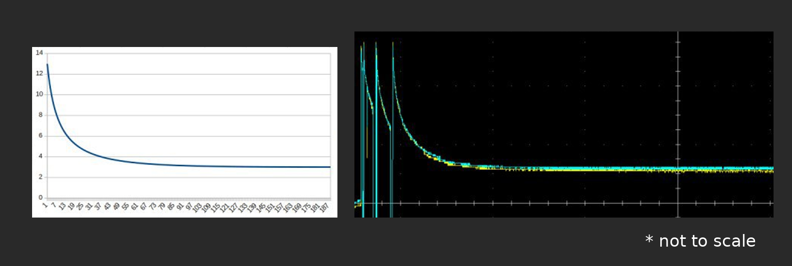 As a conclusion: resistance swap rules! : ) {actually - not, ahaha}
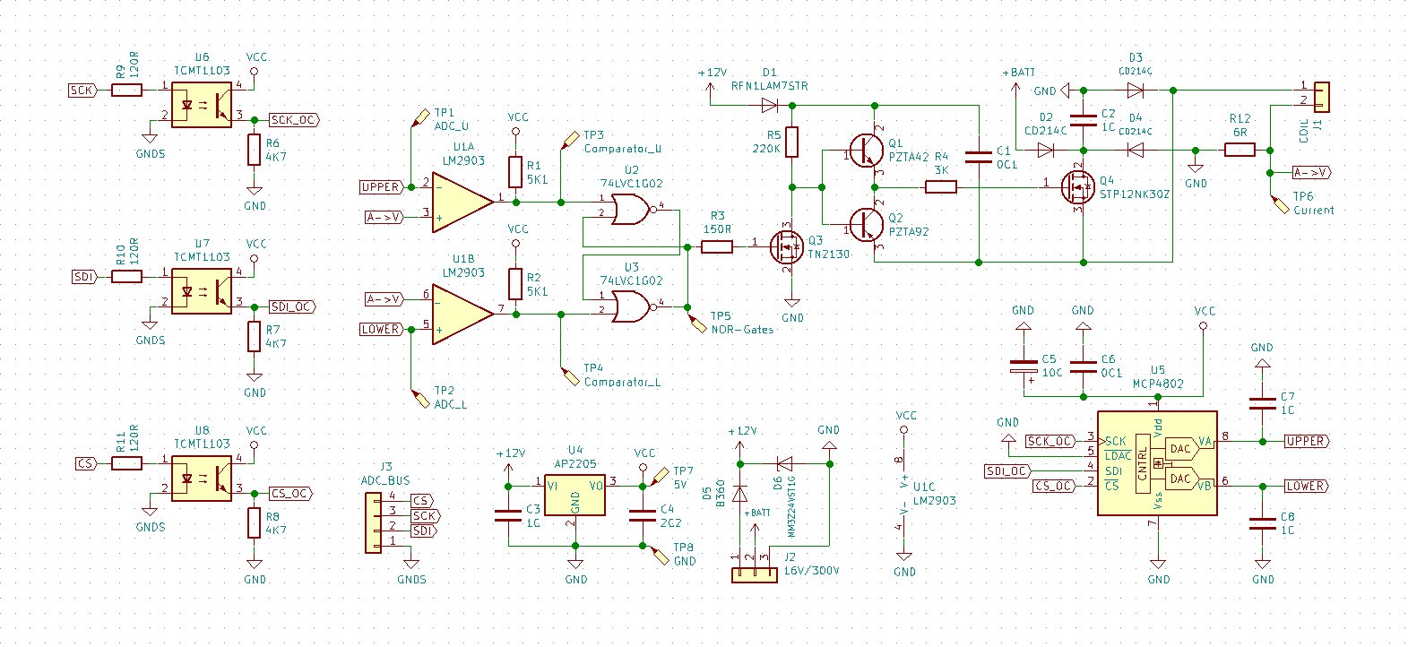 This time I chose distributor of electronic components who works internationally instead of our local shop, so I had a wider range of components to choose from! What's why now board features automotive connectors for example, way better than "PC" connectors stocked in our shops : )
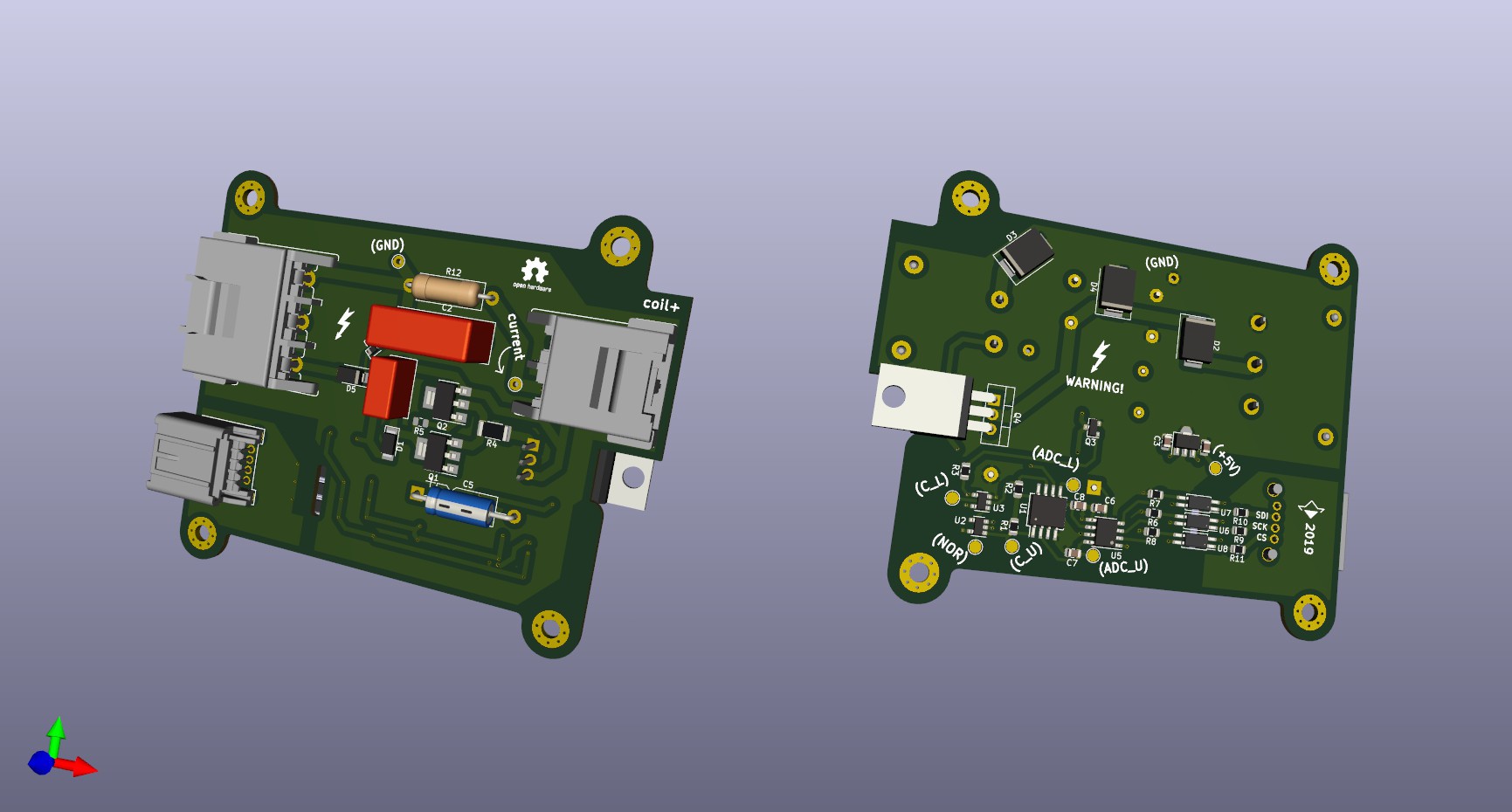 Overall, design is much more robust now, can't wait to see it working, I have plans for that one. Now it should cope with power needed to my linear actuators and I really want to experiment with transformers and BLDC motors, this board is suitable for them too, as it is a general-purpose EM field controller.
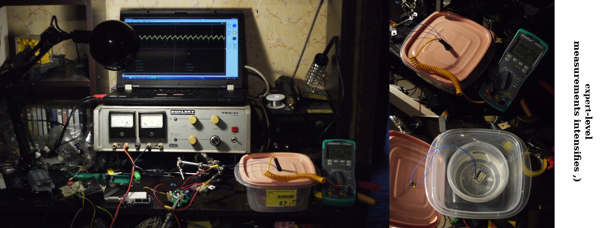 I submerged my electromagnet into a vessel with water and powered it up, recording changes in temperature. It takes about an hour to temperature to drop down for a 2 degrees in this setup, as it features some thermal insulation after all, water volume stayed untouched
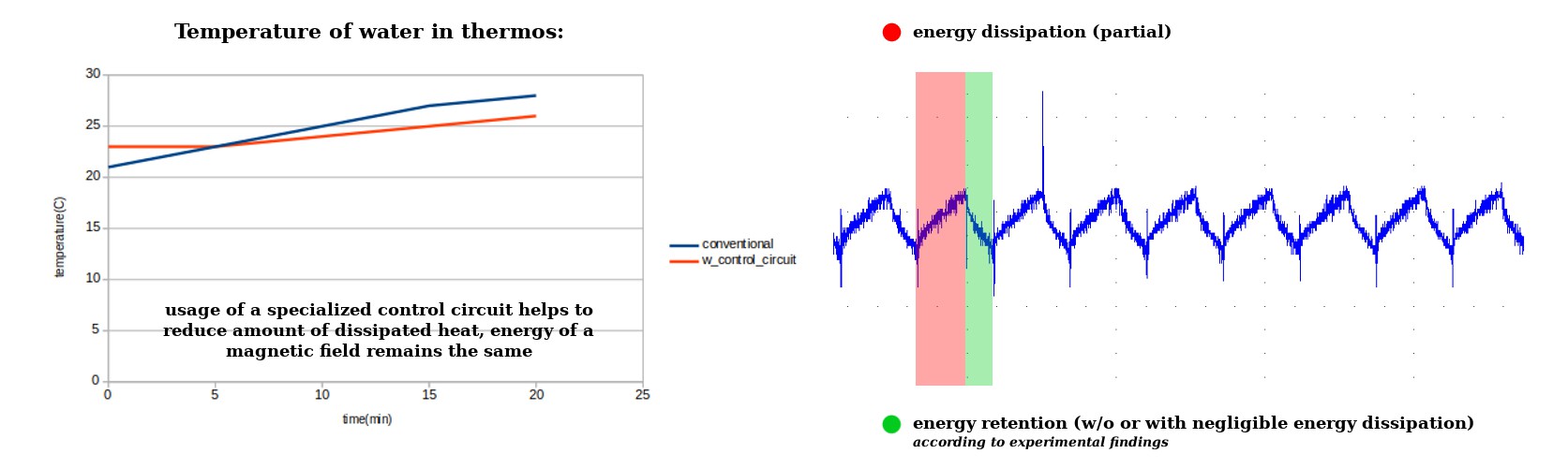 Control circuit changed situation a lot - reducing energy dissipation for about 30%
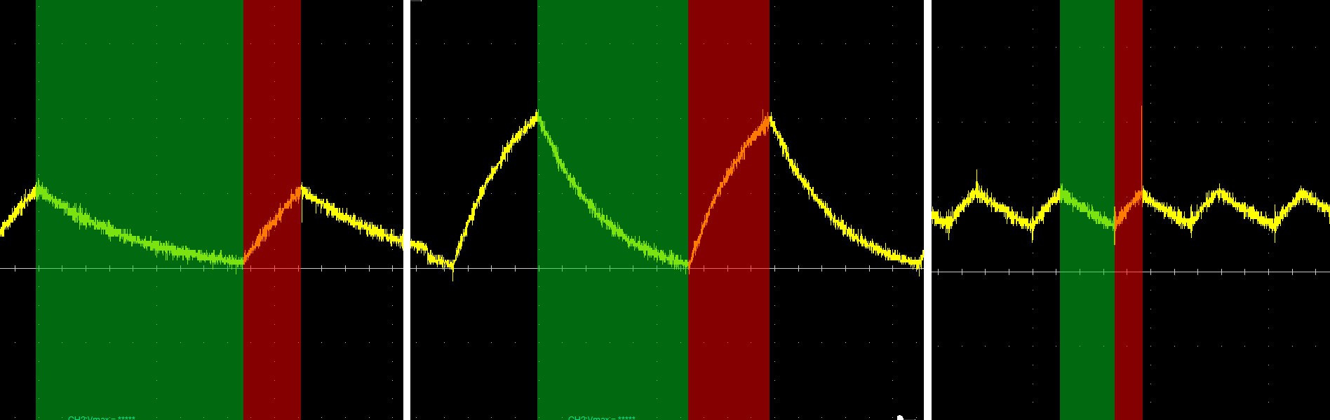 Using higher voltage, we get great charging:retention proportion, also - increase in a field-charging efficiency, according to a model presented in a previous update.
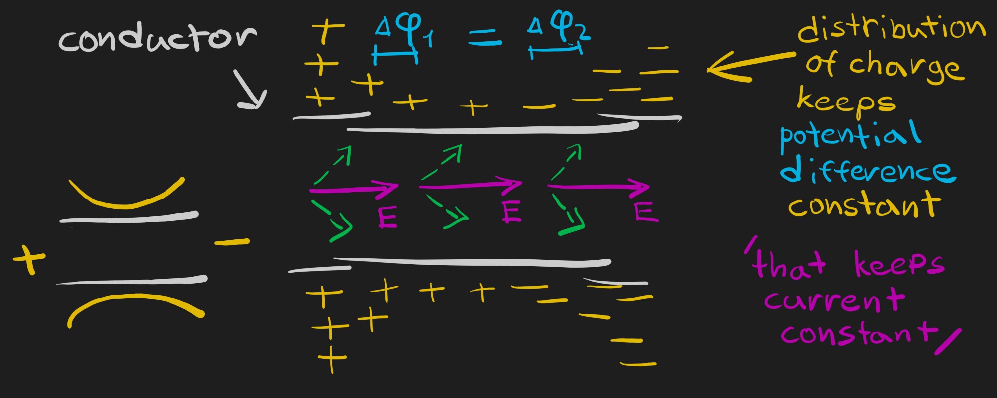 And it's fair to say, that as we have potential difference, we have potential energy between charged particles at least. Then I thought about reasons why my circuit is not as effective as needed, it was the first thing which came onto my mind: as I have diodes, it must be a tough work for magnetic field, to power up electric field and break through potential barrier!
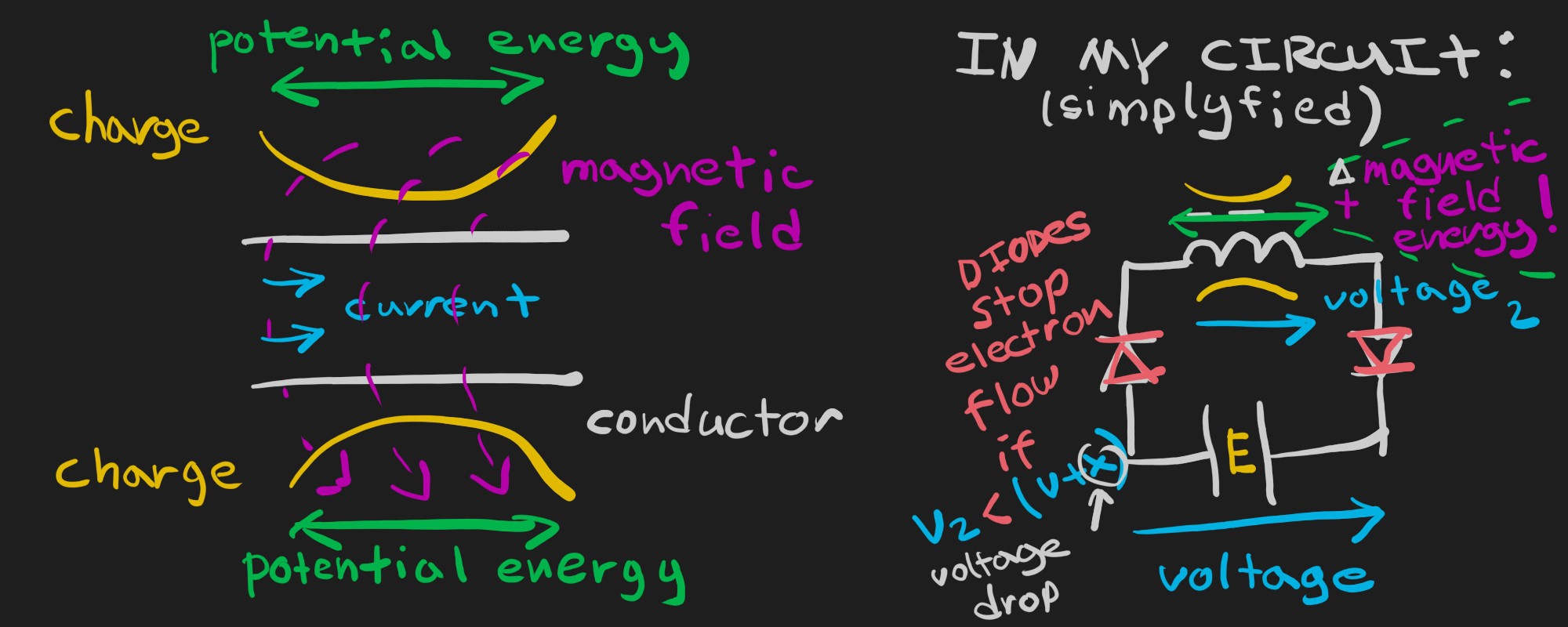 Idea of two energies on the surface of a conductor was very catchy and since that time I started thinking about it, as it seemed, that that charge is responsible not only for current, but for magnetic field, inductance and... resistance! Typically, we say, that we have two types of resistance: resistance and electrical reactance, probably it's an artificial division, caused by urge of numerical description and lack of understanding. That was OK for a typical AC applications, but not enough now, then we are talking about behaviour of an electromagnetic field. Let's have a look:
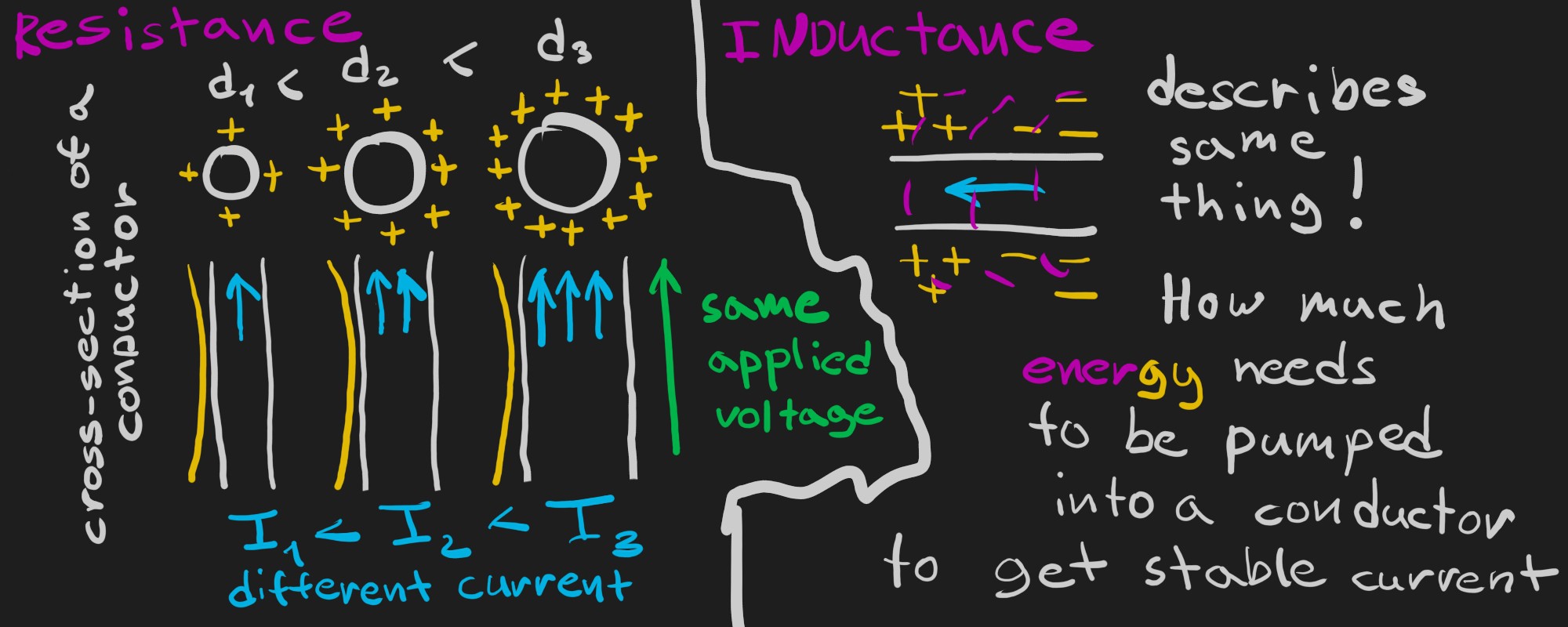 I wouldn't comment that a lot, as imagination is more important here. With same applied voltage, conductor with bigger section area have greater electric flux, and current raises proportional to R^2. On the other hand, electrical resistivity defines surface density of charge for a specific applied voltage, not a conventional "friction"
 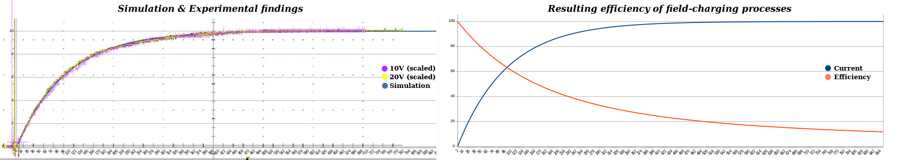 Most amazing, that you can weight roughly how a lot of things work with understanding of that.
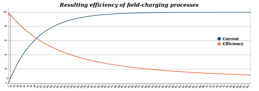
 First of all, their efficiency isn't that great as I expected, for example, 60kg of pulling force doesn't mean, that they make field equivalent to a 60kg permanent magnet, because distribution of magnetic lines is different, so in stock (with 4W of power) they cannot mimic rare-earth ones, however, with this setup I pumped in around 300W of power, and it was enough. Now I know, that it's a working concept.
 Looks evident? Well, it wasn't evident for me, even if I knew, what magnet (which I have) produces same attraction force, as a reference permanent magnet. I thought, that field shape isn't proper for this use. Today, experiment shown, that there is nothing bad with it at all, silly me!
 Yeah, that is a magnetic lock )
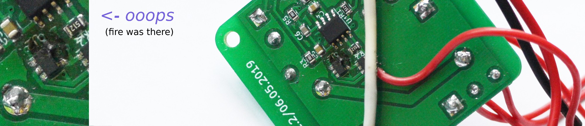 Energy goes from coil to a capacitor and in some cases, then energy oscillation is quite noticeable, it charges capacitor too much, voltage raises and does some bad stuff to LM7805 stabilizer, which powers comparator and logic gates. Couple milliseconds and they are on fire! Beautiful sight )
 Now it use three transistors instead of IC, it gives bug-fix freedom. Happily, it worked "right from the box", transistor opens as needed, as bootstrap capacitor sends needed amount of voltage to drain.
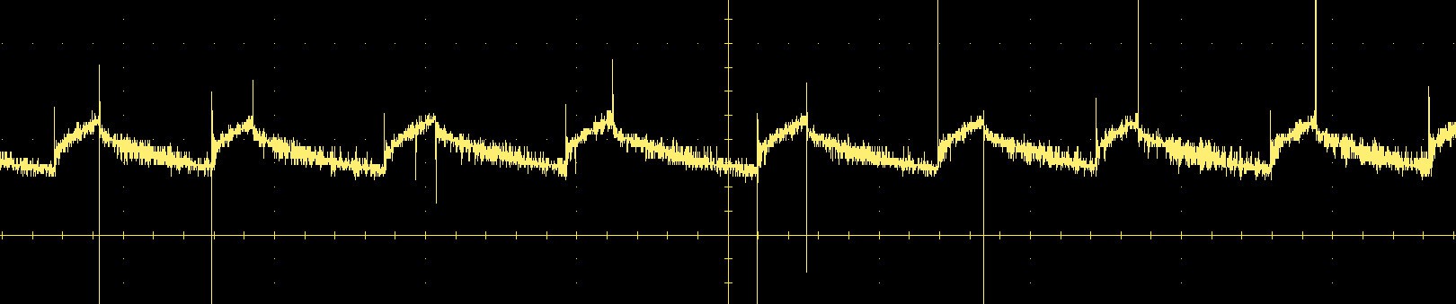 As you can see, current is quite stable. I'm not sure if I can achieve greater efficiency by increasing amount of withdrawn energy. So we can forget about kind of PWMed magnetic field! Hooray!
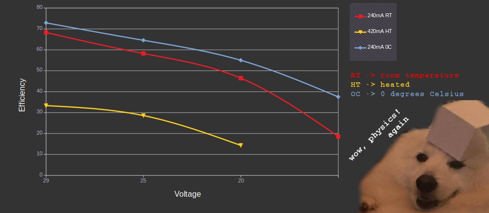 Gone wild! For some reason, supply voltage (and temperature!) affects it very much.