CapitanVeshdoki
-
Control circuit PCB (beta)
04/15/2019 at 14:38 • 0 commentsToday I partly redesigned schematics of control circuit and traced beta-version of PCB.
Now it looks like this:![]()
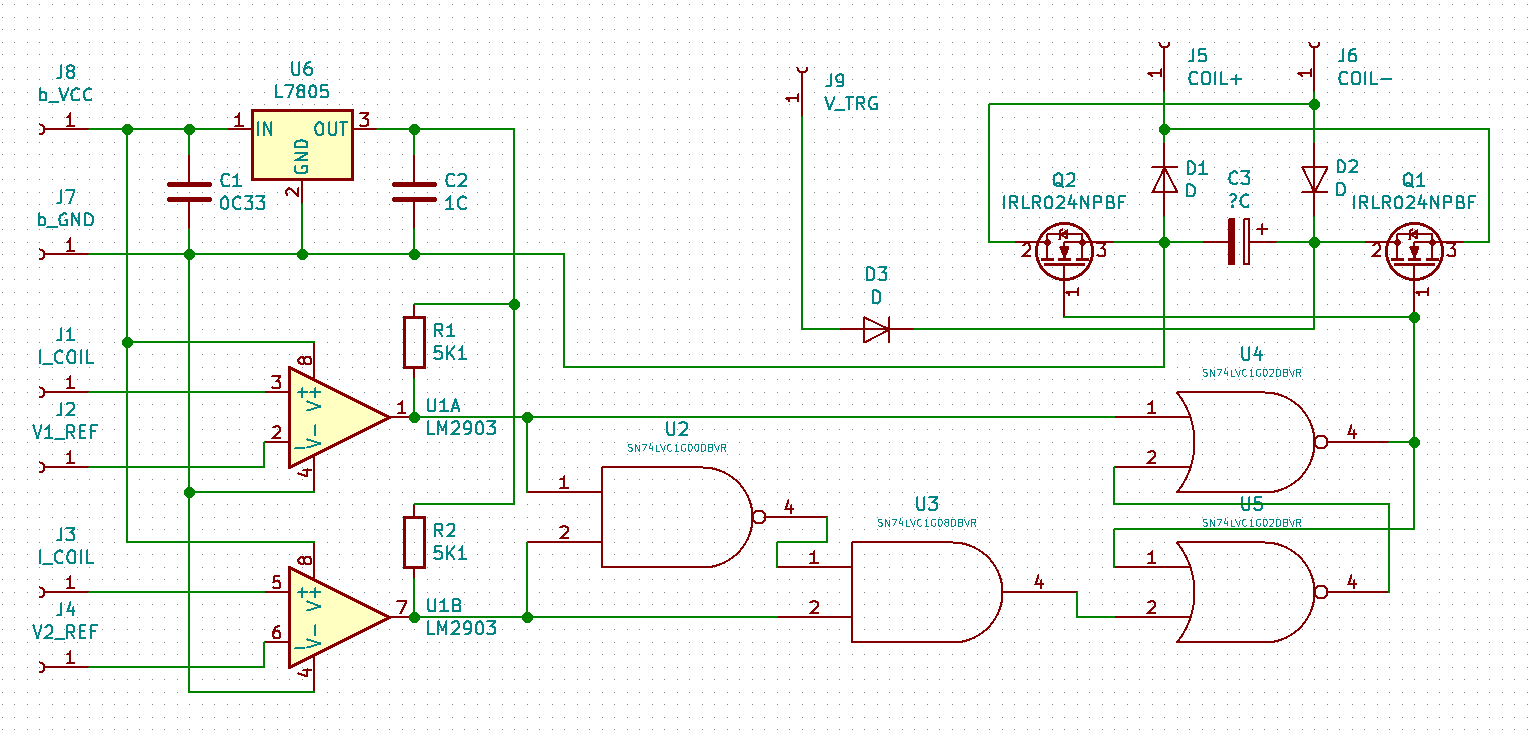
Realized, what "forbidden input state" for Set-Reset latch (two NORs near bottom-right corner) leads only to uncertainty and fatal for simulations only. So! I just threw out AND and NAND gates, as they simply messed my PCB without a large practical sense. Schematics looks much more convenient without them :)
Also I connected V1_REF, I_COIL and V2_REF inputs more precise.
It looks simple, but hey! So much things to control here:
- Energy of an impulse (through V1_REF and V2_REF)
- Lowest voltage of impulse (V_TRG, target voltage) aka impulse duration, since with bigger voltage you can achieve bigger currents, faster energy dissipation. Voltage on capacitor C3 should be greater (due to charge during demagnetization) or equal to V_TRG
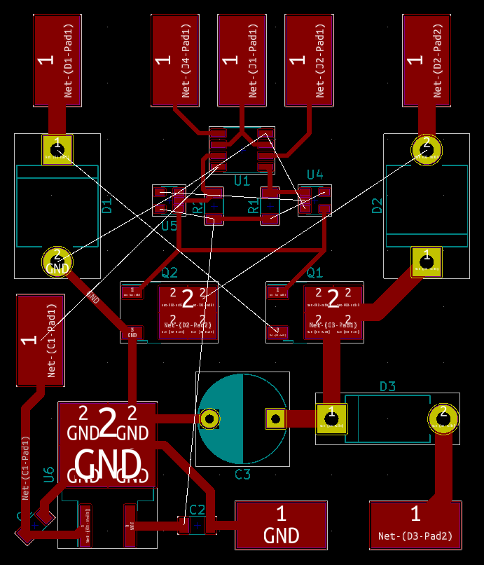
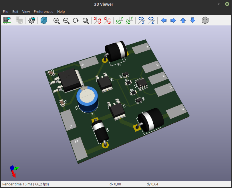
Here is how PCB probably would look like:![]() P.S. Capacitor is going to be external in this version, to find needed capacity
P.S. Capacitor is going to be external in this version, to find needed capacity
Main question for now - how to produce it. I'm not into making two-layer PCBs at home (too impatient for it, even if process is encouraging), I would try to trace everything on one layer with minimum wiring.![]()
-
Control circuit?
04/14/2019 at 18:09 • 0 commentsWell, it's time for an update!
First of all, I've made a sketch of schematics, which I gonna use there:![]()
P.S. Yes, some of I_COIL and V?_REF inputs got entangled here : )
It consists of three parts, briefly:
1) One part is watching over current through electromagnet (I_COIL inputs) as currents represents energy.
2) One part is a SR NOR latch with protection from restricted state (1,1) implemented here on logic elements U2 [NAND], U3 [AND], U4 & U5 [NOR], because I can't find component, which can do similar job.
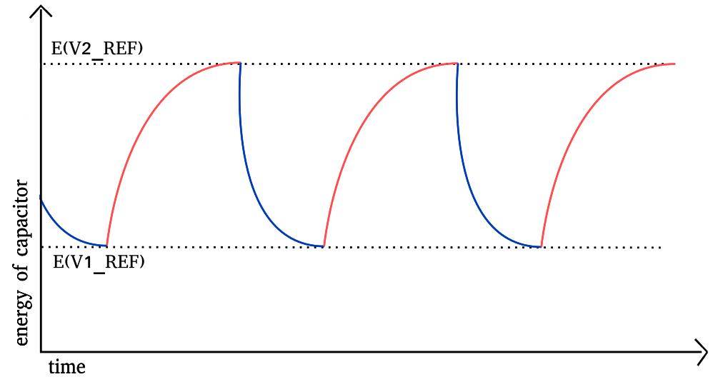
3) Capacitor C3 acts like a energy storage, it charges from process of demagnetization and from source V_TRG as well, if voltage on V_TRG is greater than voltage on capacitor. After charge, it discharges on electromagnet through N-channel MOSFETS Q1 & Q2Capacitor C3 is actually pretty important, what's going on there is shown on this picture:
![]()
According to Ohm's law, you can't pump infinite current into electromagnet with finite voltage, because coil has a resistance. We can presume then, what electromagnet contains finite energy. If it so, after we reached maximum current possible with some voltage, we can't do anything more for strength of our magnetic field, from this point we just waste power onto heat. What we can do with what?
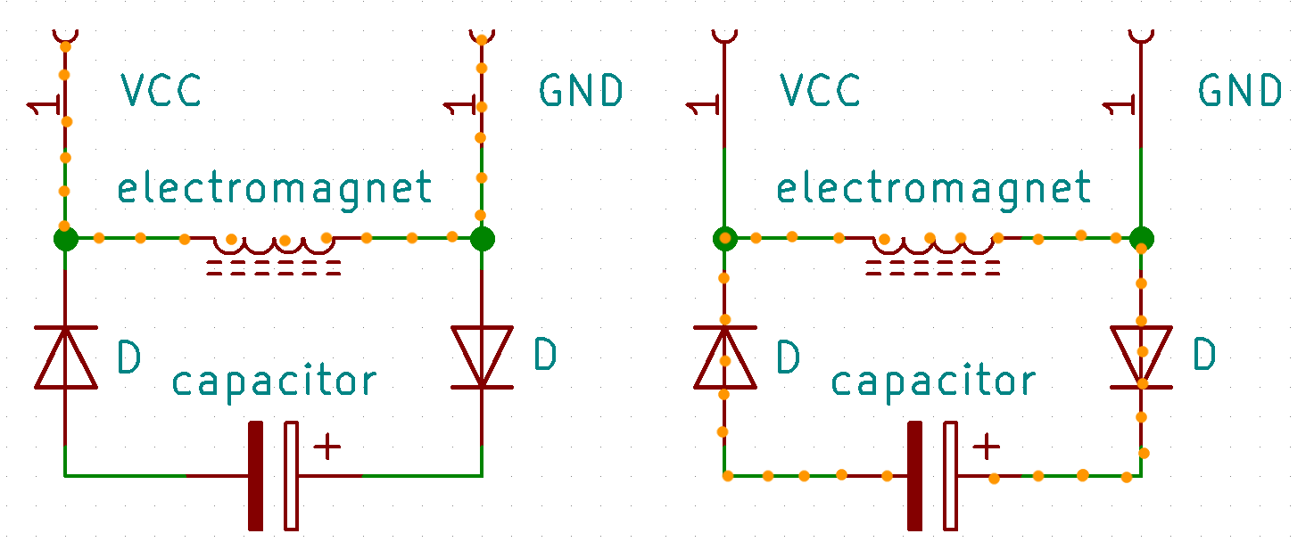
One way - is to retain and inject energy cyclically, like shown on this picture.
Then you disconnect power supply from the coil, current continues to flow in the same direction as before, from COIL+ to COIL- (if we don't mind what electrons are moving from negative to positive, ohhh reality), as there is no power supply now - current flows through diodes D1 & D2 and by that charges capacitor C3.![]()
SR NOR latch is a Set-Reset "switch", it controls charge and discharge of a capacitor.
V2_REF and V1_REF - reference voltages, they are gonna be compared with a voltage (I_COIL) on a resistor connected in serial with a coil. (voltage on this resistor is proportional to the current flowing through electromagnet) - If voltage on a resistor is lower than a reference voltage V2_REF it means, what energy on coil is lower than needed - SR NOR latch switches into state, there capacitor discharges onto electromagnet. - If voltage on a resistor is higher than a reference voltage V1_REF, capacitor charges from energy, contained in magnetic field due to demagnetization process.
By adjusting V2_REF and V1_REF we can tune bounds in which energy of magnetic field gonna be changed. It's very useful - even if field performs work, charging-discharging process would be stable, that can't be achieved through constant periods of charge and discharge. And capacitor is protected from over-discharge as it connected to power supply V_TRG.
That's pretty much it! On this week I would try to improve schematics, PCB fabrication is coming right after that. Also, manufactured stripes would be tested with permanent rare-earth magnets, measuring contraction force.
linear actuations for everyone!
cheap artificial pseudo-muscles here

 P.S. Capacitor is going to be external in this version, to find needed capacity