 Jana Marie
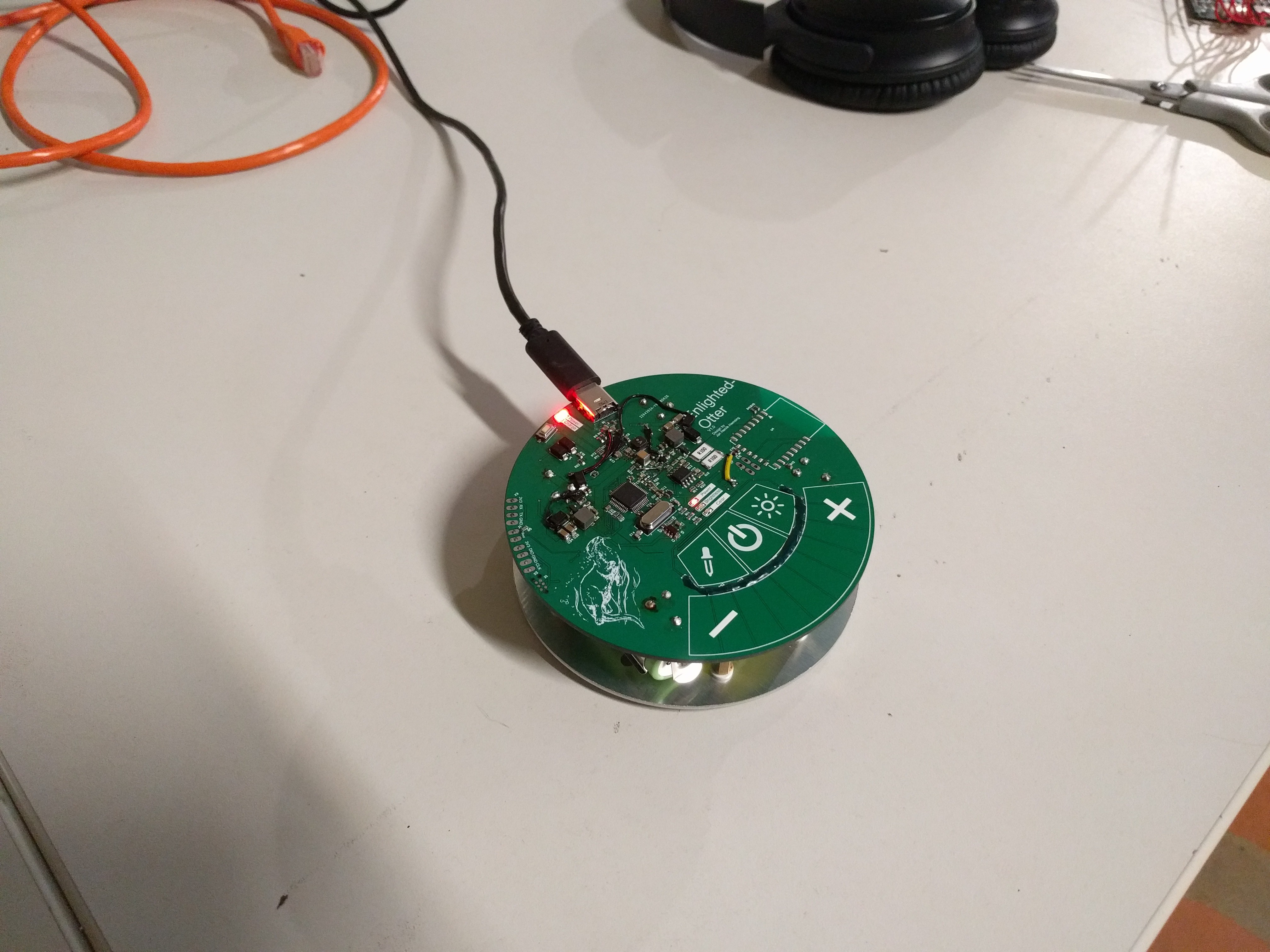
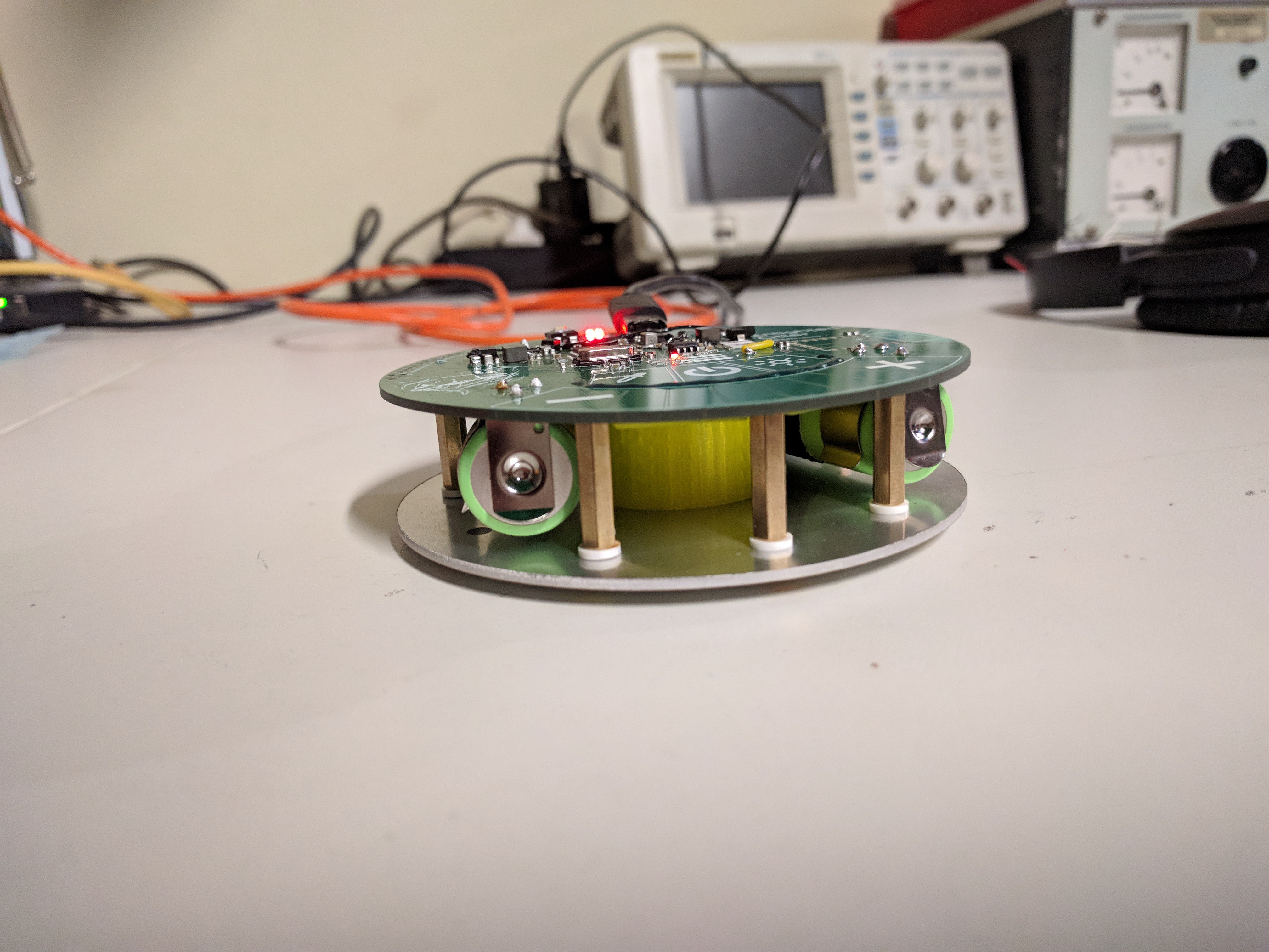
With the boards from the previous two Logs we can already assemble an Enlightened Otter. There is not much to that: Snap in two batteries, add the 3D printed part, add insulators, add nuts and you're done.
The software is written in C with the STM32 HAL Lib and Makefiles. The difficult part here is the hardware initialization, since most of it runs offloaded from the CPU using HRTIM triggered ADC.
All the bodges of V1.0 where removed in V1.1. A major problem both versions have, is ghost touch input from boost converter noise. This can be solved by lowering the sensitivity, but then the input is no longer so responsive.
The charging of the batteries and the battery operation function perfectly. Also the Boost converter works very well, but the Mosfets get very warm, in version 2.0 a new package has to be chosen. The current measurement and the controller have no problems, a current control with a current ripple of < 0.5mA is possible.
The protective devices trip in the event of a fault.
On the board I have provided a footprint for an ESP, but I haven't equipped and tested it yet
Discussions
Become a Hackaday.io Member
Create an account to leave a comment. Already have an account? Log In.