Introduction
A capacitive touch pad is something quite simple. If you google it, probably will easily find a bunch of material explaining how it works.
Today there are some dedicated ICs as well as hundreds of microcontrollers that have some IOs with capacitive touch input option, but at the time when I came up with this simple solution such devices weren't that cheap and easy to find.
Even considering today's devices, I believe this circuit still super valid! Is an awesome call for those hardcore fellows that want to see the raw sensor input (like me) and the simplicity along with sensitivity is great if you have some applications as tick glass, door, table, etc.
I already added some multiplexers to read multiple buttons in a touch keyboard and the performance was outstanding. Maybe if I escalate this multiplexing version would be possible to create a gesture sensor, but let's keep this for another project...
Prototype
I like to put the more juicy part of the project description at the beginning hahaha, in this case I made a simple video showing the sensor signal
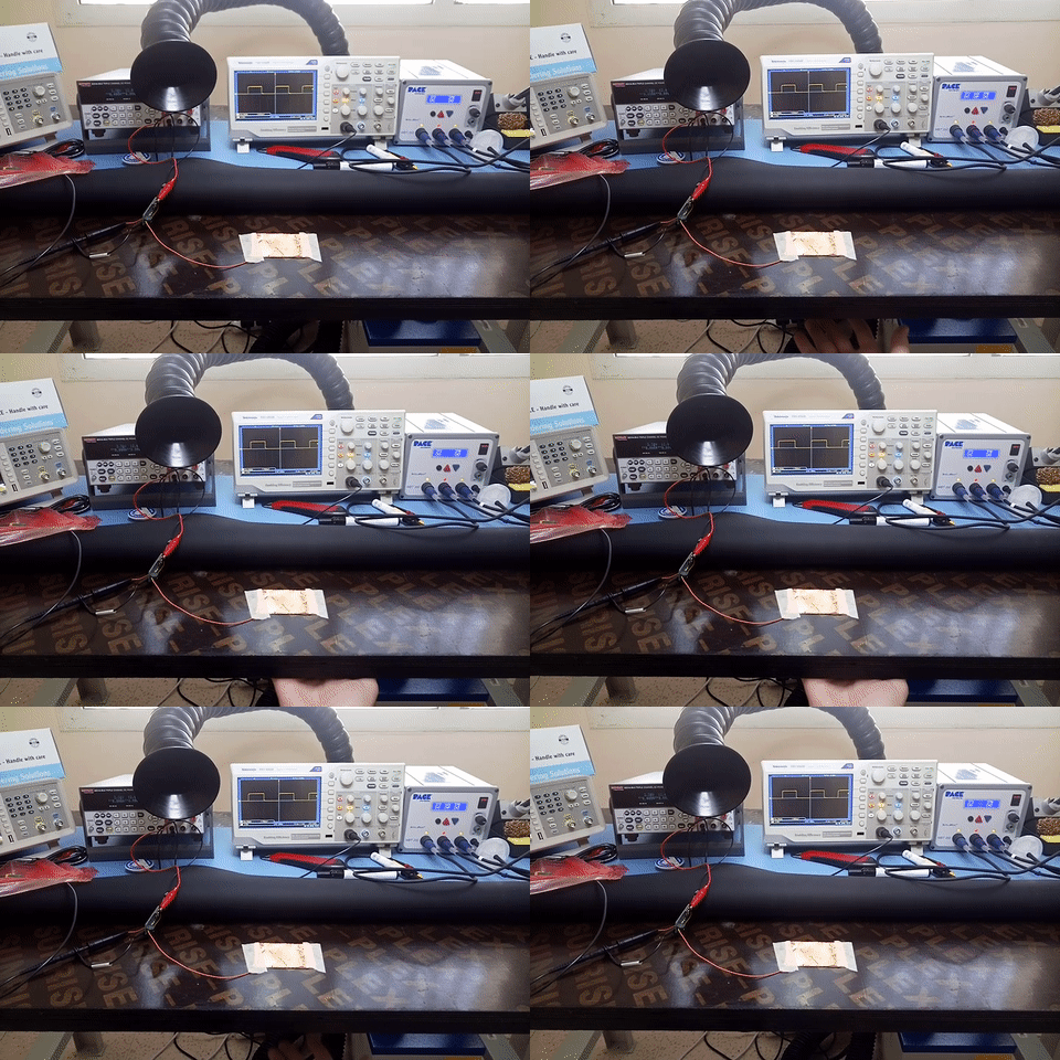
In this sample you can see a significant difference in the signal, the positive width goes from 2.5ms to 2.8ms (300us is quite easy to measure).
This test was made using a wood bench with ~3.5cm thicknesses .
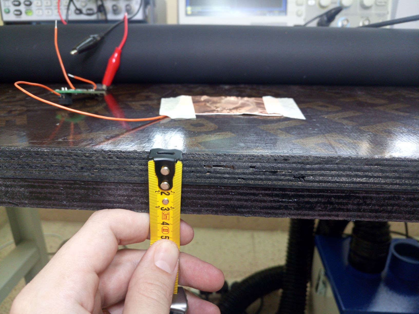
Of course, this type of device is very sensitive to the environment and the firmware should consider the proportional variance to figure out when somebody is "pressing".
Some other considerations:
I recommend you to look the schematics to understand this considerations.
- This example uses the counter's Q8 (equivalent to solder R10 jumper);
- C1 was left empty. Adding a parallel capacitor decrease the sensitivity but increase the stability;
- The connector J1-2 is the actual pad input, J1-1 is the ground connection, and it can be used to add a shield or use a parallel capacitor as sensor element.
- Adding a shield might decrease the sensitivity, it may be a good idea to put some material to add a gap between the sensor and the shield, otherwise the shield-pad capacitance could ruin the signal.
- Frequency is different for different materials, different if you add a parallel capacitance, different if you add a shield and so on. That's why I added jumpers on each counter's Q, you can solder the one is better for your application.
- If you want to detect a finger instead of a hand and/or use a smaller pad you can achieve it increasing the sensitivity by using another output. With great power comes great responsibility and shielding might be needed as well.
I made a video showing this experiment. Watch it, but take in consideration the list above (because I forgot to say 50% of what I wanted to say).
Basic theory
I like to start all my circuits from some features list but in this case the single and main feature is to create a sensitive capacitor touch pad. To achieve that I'll bring a modular and easy to implement solution, designed based on the following blocks diagram:

The principle here is using the finger or hand capacitance as the charging/discharging cap of an RC oscillator. As this capacitance is quite small, the oscillation frequency will be high and you'll need a faster and more expansive microcontroller to read it, especially if you want to increase the sensitivity. A tricky solution for this matter is just a simple frequency divider.
Circuit design
As all electronics circuits, now there are infinite possibilities. I used many options in different circuits but for this specific post my solution is bellow:
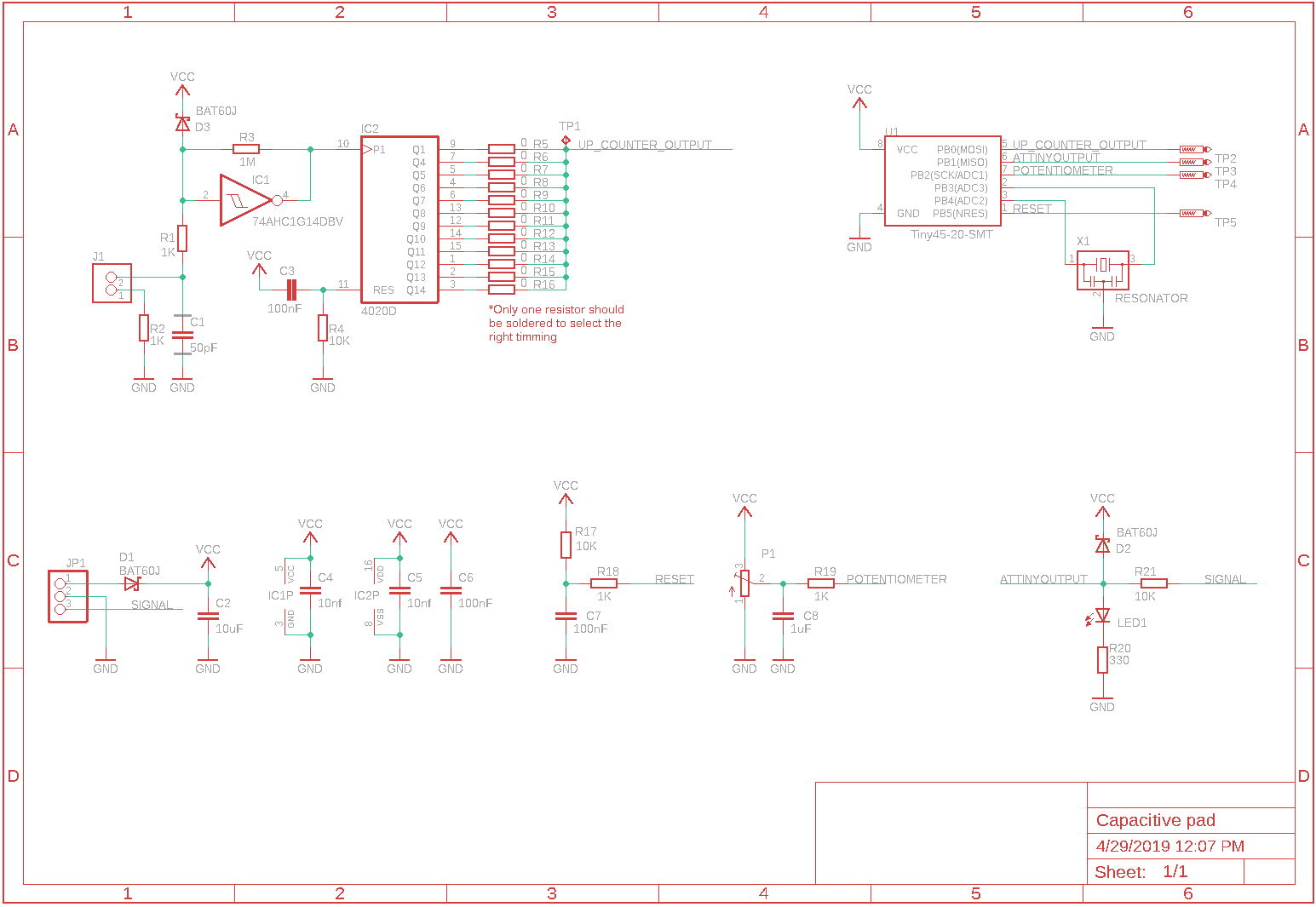
- R1, R2, R21, D1, D2, D3 are for protection;
- R18 and R19 is for protection during programming;
- X1 is not necessary (I added just because wasn't sure about time measurement using internal clock, maybe in more adverse...
 Gabriel D'Espindula


 georg ottinger
 Thomas
 Kelly Heaton
 tobi tubbutec
THank you Gabriel,
When i am ready to start on it, I will let you know what i do , and where i get stuck.
I did a thermostat with touch screen, but the screen is expensive.
I will try to rewrite everything for push buttons and use touch buttons.
I will keep you posted.