-
The Wiring Diagram
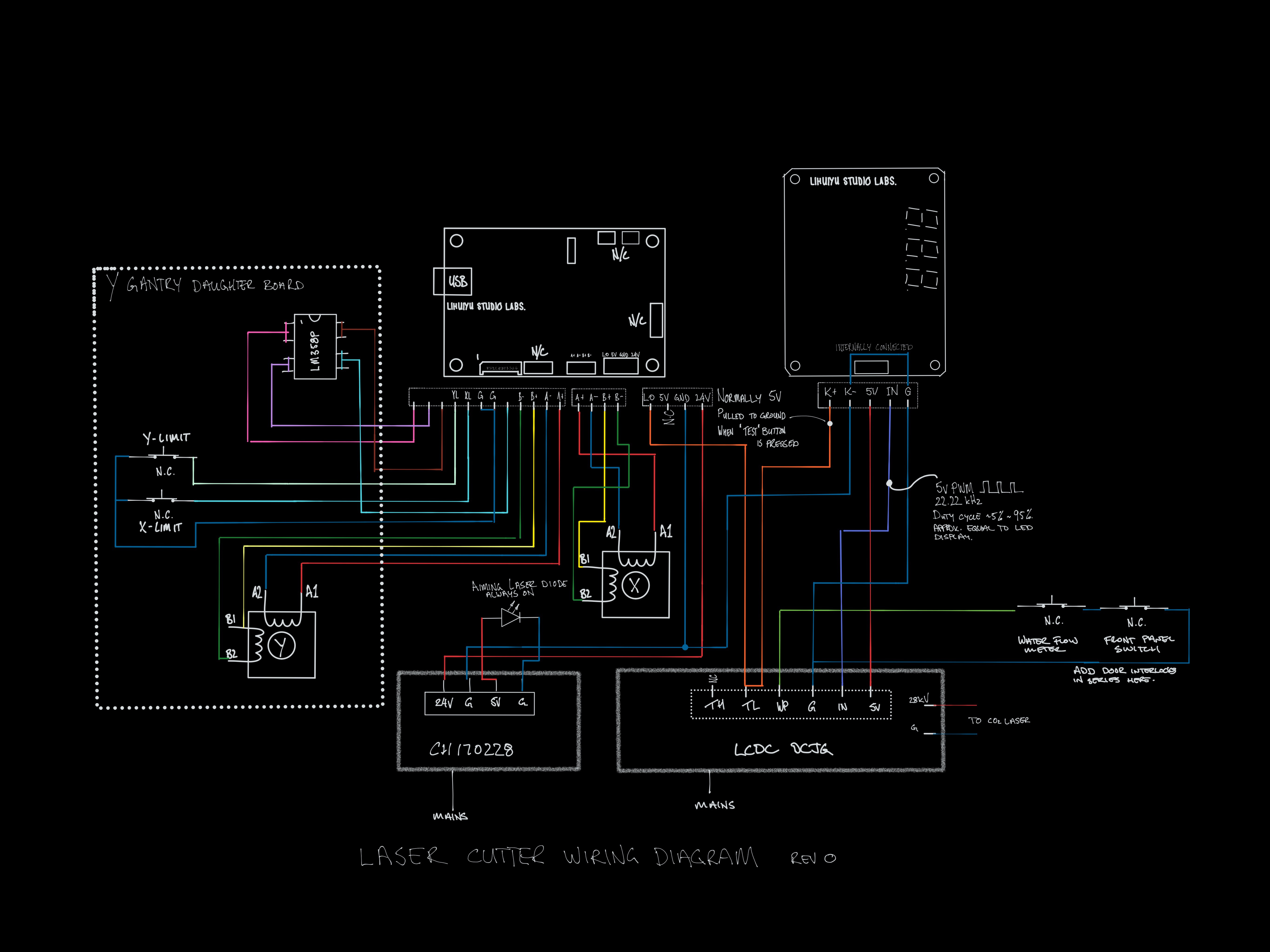
04/28/2019 at 11:45 • 0 commentsI have gone through the wiring and sketched it out. I also took out the laser power control board (the one with 888 on it) and pit it in a logic analyser. The IN pin sends a 22.22kHz PWM with a duty cycle that more or less matches what is shown on the display. The K- pin is pulled up to 5v normally and to ground when the test button is pressed.
![]()
-
Stepper & limit switch daughter board
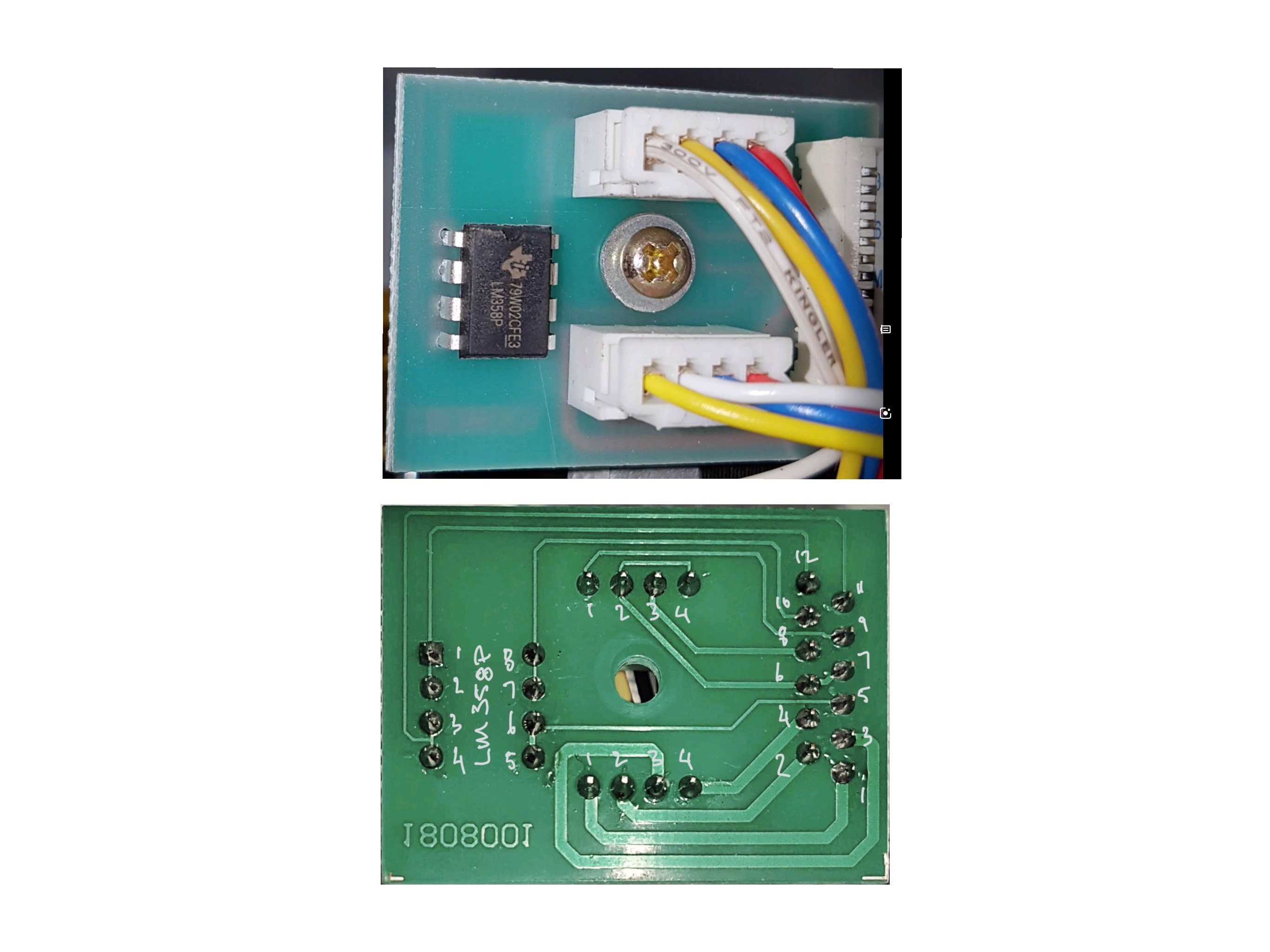
04/26/2019 at 11:20 • 0 commentsThis daughter board is mounted on the y gantry and provides a connection point for the Y-axis stepper motor and the X & Y-axis limit switches
![]()
It connects to the main board with an FFC ribbon cable. After taking a look at Don’s Laser Cutter Things I found out that is is a 12pin 1.25mm pitch FFC cable and ordered a connector from RS Components. I searched for “CONN FFC VERT 12POS 1.25MM”.
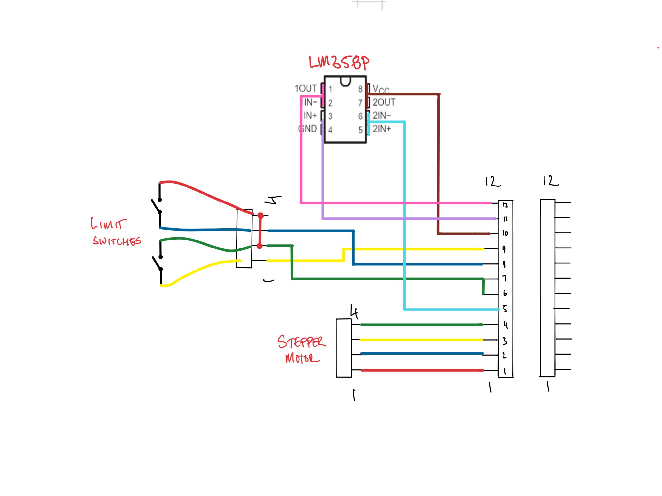
After looking at the circuit, I am really confused. I have sketched out the circuit below to make it a bit clearer. If anyone knows what the opp amp is doing, let me know. I will take a look at the controller later to see if I can work out what is happening....
![]()
-
Laser PSU
04/25/2019 at 12:26 • 0 commentsLike everything on this laser, it is very difficult to get any documentation for the PSU.
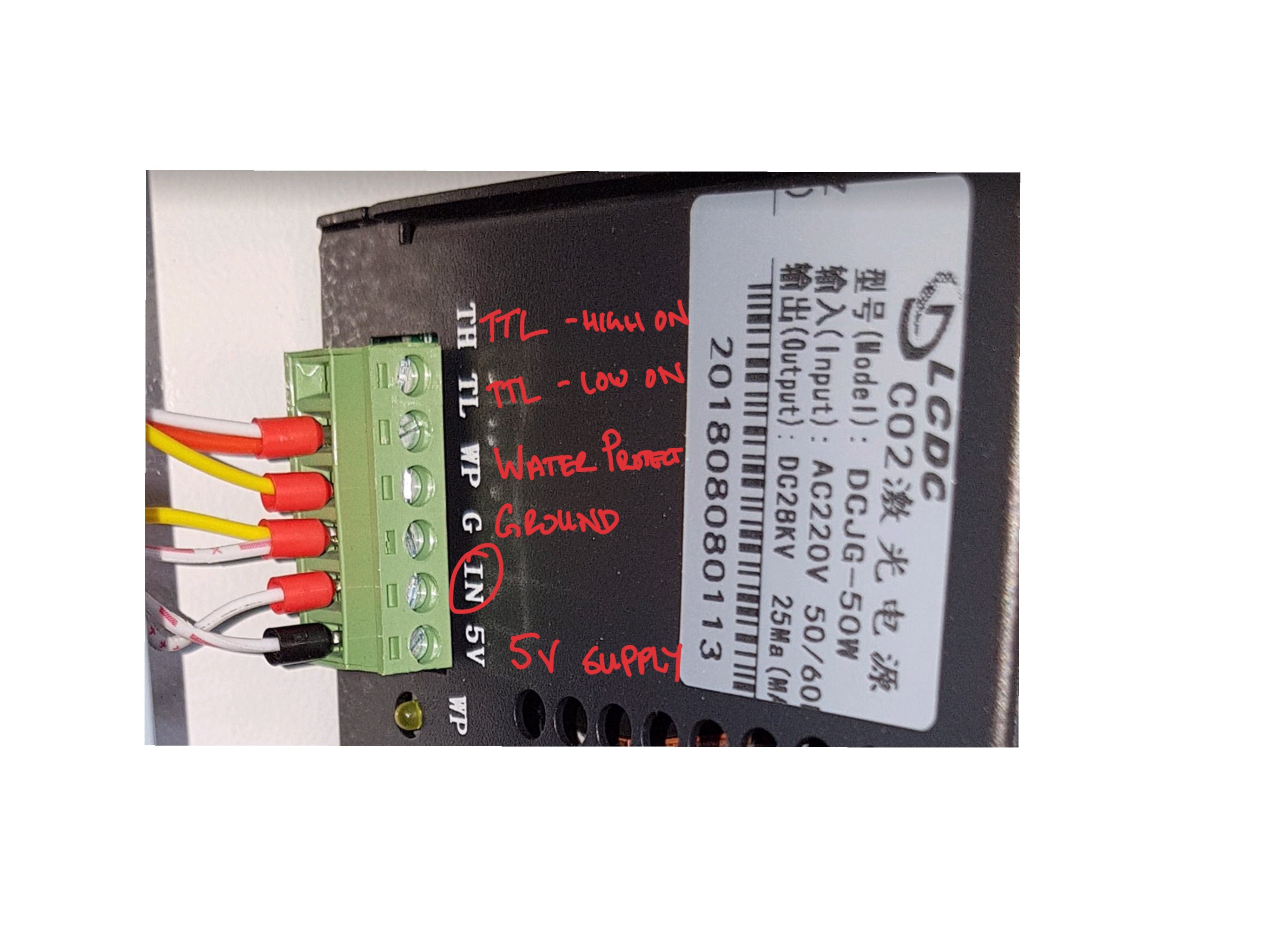
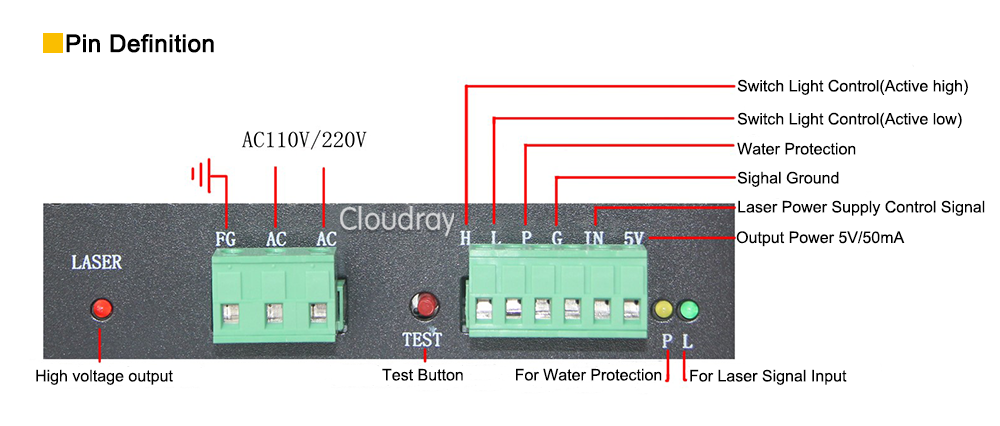
Based on the markings it is a LCDC DCJG-50W. The photo below shows the low voltage connector. I will leave the high voltage connector to the laser allone.
Out of the box, it is setup as shown in the photo below. The laser intensity is controlled by the IN pin. The power controller on the front panel provides a signal 0 to 5v (or PWM?) and the laser power is adjusted accordingly.
I think that the TL pin is connected to the "test" button and the laser is on when it is pulled to ground.
I plan to connect the spindle / laser PWM from controller to the TH (high on). I think that i should still be able to use the TL pin for testing but i am not sure what the power level will be if the IN is not connected. Maybe I should have a voltage divider pot next to the test button so that I can set the power with that. I'm Not sure how that will affect the power during normal operation though. I might need to do some testing.
I also spoke to the supplier of my laser cutter about max power that I can run the laser tube at. He said 25mA so hopefully i can find a way on the PSU to limit the current accordingly
Finally, I have been reading all over the internet about installing a ammeter in series with the laser tube to make sure that I am not exceeding the rating so i think that i will do that to. I am a bit worried that it may affect the operation of the laser. i have seen that some of the lasers have the ammeter fitted in the factory so maybe is to not a problem. let me know in the comments if you have any experience.
I'm also not sure if there should be some sort of "laser enable" pin that i need to connect to the controller.
![PSU LV connection PSU LV connection]()
LCDC DCGJ- 50W PSU LV connection ![]()
-
The new controller board
04/25/2019 at 11:48 • 0 commentsI have been looking around for a replacement board for the motion and laser control. There are lots of boards to choose from, including some that can be swapped out directly but i like the look of the board by Bart from buildlog.net. http://www.buildlog.net/blog/2018/11/grbl_esp32-development-board-version-3-1/
The manufacturer of the laser cutter has made some interesting choices for the motor and limit switch connectors (12 pin FFC) so I have decided to make my own board based on the schematic at the link above with some modifications for my case.
When I was researching parts, I realised that everything was available as pre-made modules which will save me a lot of time and hassle soldering smd parts. It will also let me assemble to circuit on a breadboard and get it working very quickly.
Upgrade Budget Laser Cutter
I have a laser cutter from China, similar to the K40 (50W 4060) it works out of the box but the software stack and UX needs work.
