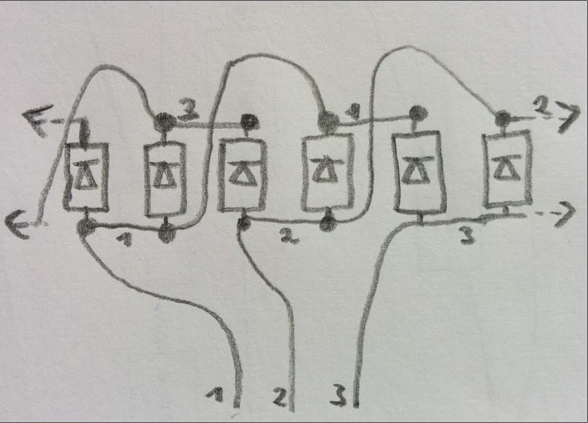
The circuitry for the blinky looks roughly like this:

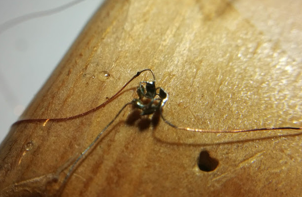
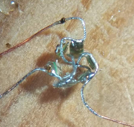
The LEDs are standing upwards like the stones of Stonehenge with the face looking outwards. Connecting the three wires is the more complicated part of this project. It was done under a microscope.


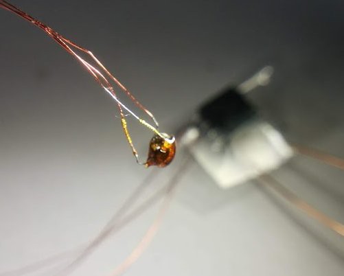
After a quick check if everything is connected as it should, i melted this wire mess in a small rosin drop.
 Time for hacking a small program into the attiny13
/* (c) 2019-05-01 Jens Hauke <jens.hauke@4k2.de> */
/*
 * ATMEL ATTINY13a
 *
 *       +-\/-+
 * PB5  1|    |8  Vcc
 * PB3  2|    |7  PB2 ++ Charlieplex
 * PB4  3|    |6  PB1 ++ 6
 * GND  4|    |5  PB0 ++ LEDs
 *       +----+
 */
#include <inttypes.h>
#include <avr/eeprom.h>
#include <avr/interrupt.h>
#include <avr/io.h>
#include <avr/sleep.h>
#include <avr/wdt.h>
#include <util/delay.h>

static inline
void init(void) {
    DDRB =  0b0000111; // 0-2 output
    PORTB = 0b0000010;
}

#define STEP 150
static inline
void loop(void) {
    PINB |= 1<<0;        // Toggle Pin PB0
    _delay_ms(STEP);
    PINB |= 1<<1;        // Toggle Pin PB1
    _delay_ms(STEP);
    PINB |= 1<<2;        // Toggle Pin PB2
    _delay_ms(STEP);
}

int main(int argc, char **argv)
{
    init();
    while (1) loop();
}
(Did you know that writing a 1-bit into the PINB register of an AVR toggle the output state of PORTB? Handy for time critical toggles…)
Does it light up? YES!
 Jens Hauke


I really think you should market this . I'm a small scale model builder I am working on a project and I have been looking for something like this online for my models .There are a lot of modelers out there that would put this application or product to use .. I would like to learn more or if I could obtain a unit from you in the future .. Thank you for your skill level .. Walter Hgh