MasterOfNull
-
Contribute!
05/02/2019 at 16:38 • 0 commentsPrint this, put it on a robot, and you will be added to the project.
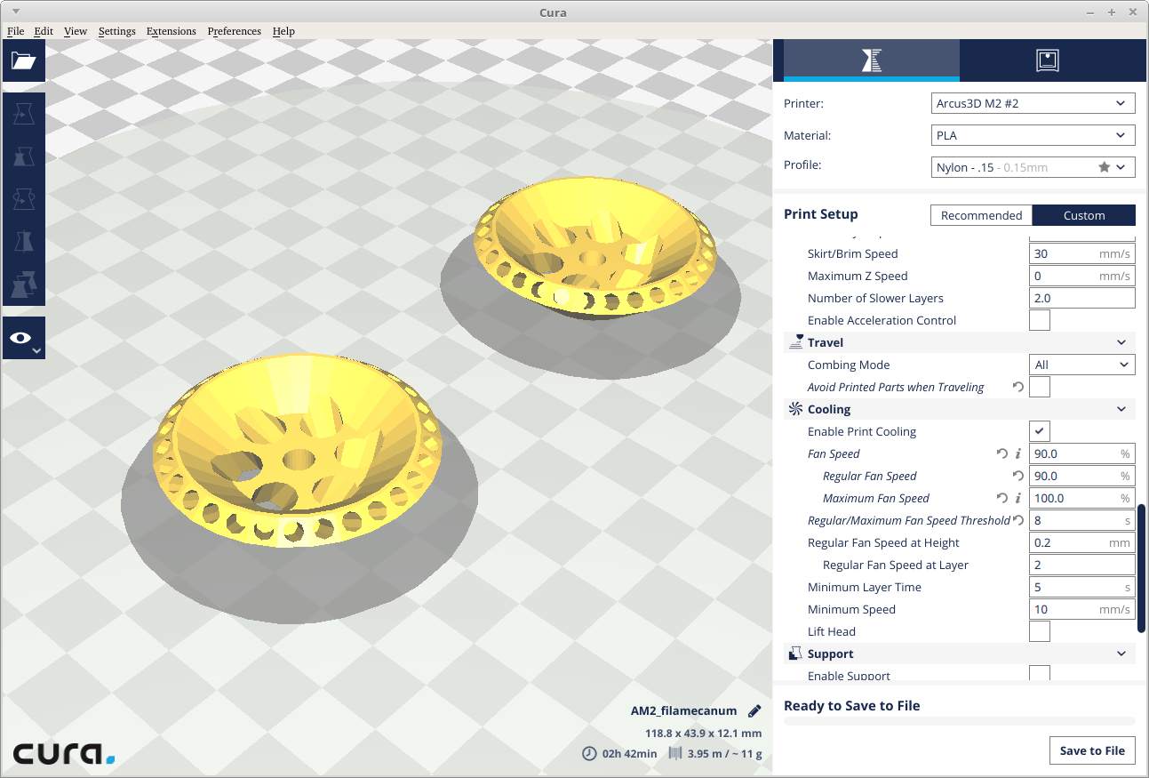
Each wheel (two halves) takes 11g of filament and about 2 hours to print. There are two different models exported to flip the direction of the 45 degree offset, like regular Mecanum wheels. The holes in the center of the rim are also rotated, so that you have a reference for which one you have in your hand when you go to assemble them.
The filaments press fit nicely right now and the model didn't require any cleanup at all. Print with 'combing' enabled, but 'avoid printed areas' turned off. The overhang resulting from the increasing diameter from base to top is just about perfect, but you'll probably need to go a little slower and have good cooling to keep it looking clean.
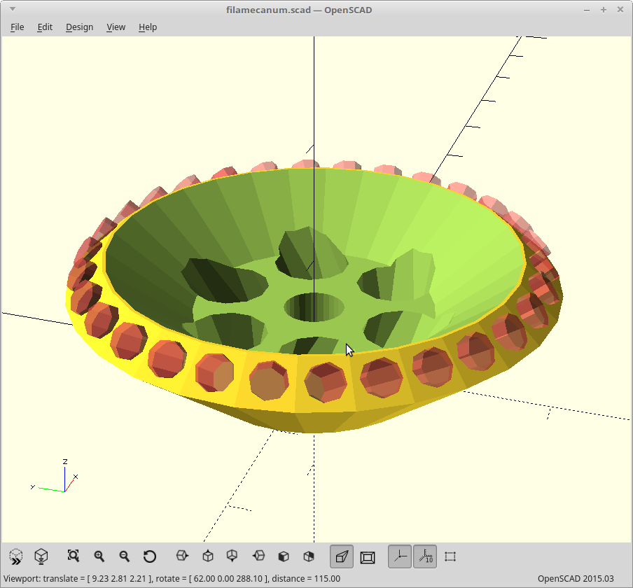
The OpenSCAD was a little hasty, and is not really parametric. It will need some tweaking to scale and modify things.
As modeled, this has a 5mm shaft size, is 30mm wide, and 90mm in diameter right now. It takes 30 sections of 80mm length of 2.8mm OD string trimmer filament.
But that could be whatever is needed. Going very much larger will require thicker filament (and I don't think they make it thicker), going smaller will require thinner. The upper limit for the size could also be fixed by making the rim larger, which would allow for using more filaments. At the extreme, you could also set them up alternating, weave them, and get a Mars rover style tire. Just let me know.
It could also use a way to keep the two halves from spinning with regard to each other, like indexing pin holes. Right now if you compress the entire tire, the center halves rotate against each other. Conversely, if you spin the two halves with regard to each other, you can change the tire size! Useful? Probably not, but who knows what people will think up...
-
Results
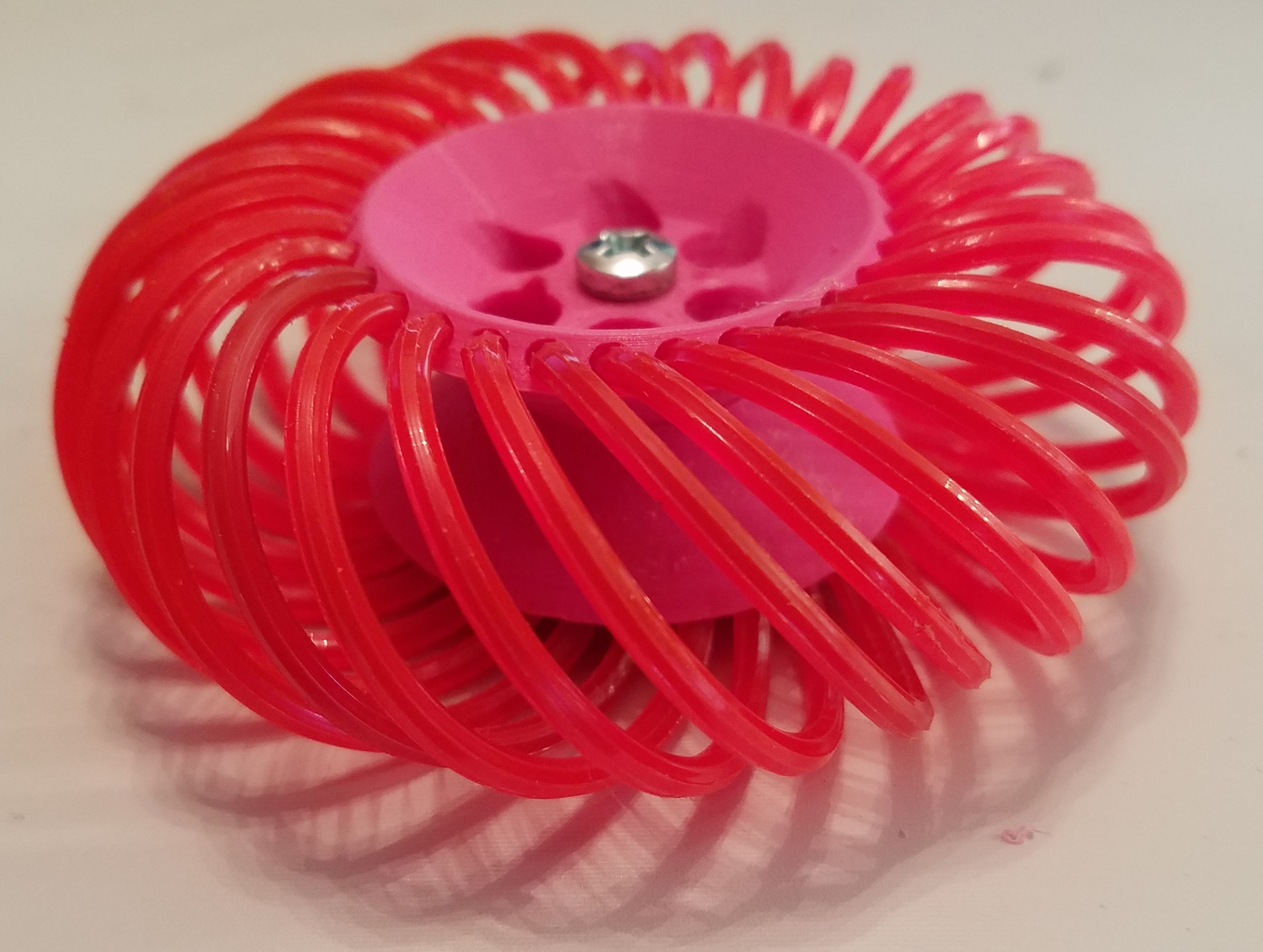
05/02/2019 at 15:40 • 0 commentsPrinted two hubs, and cut 30 pieces of 80mm long string trimmer line.
Put them in.
![]()
Now, if I only had a robot to try them on. Anyone?
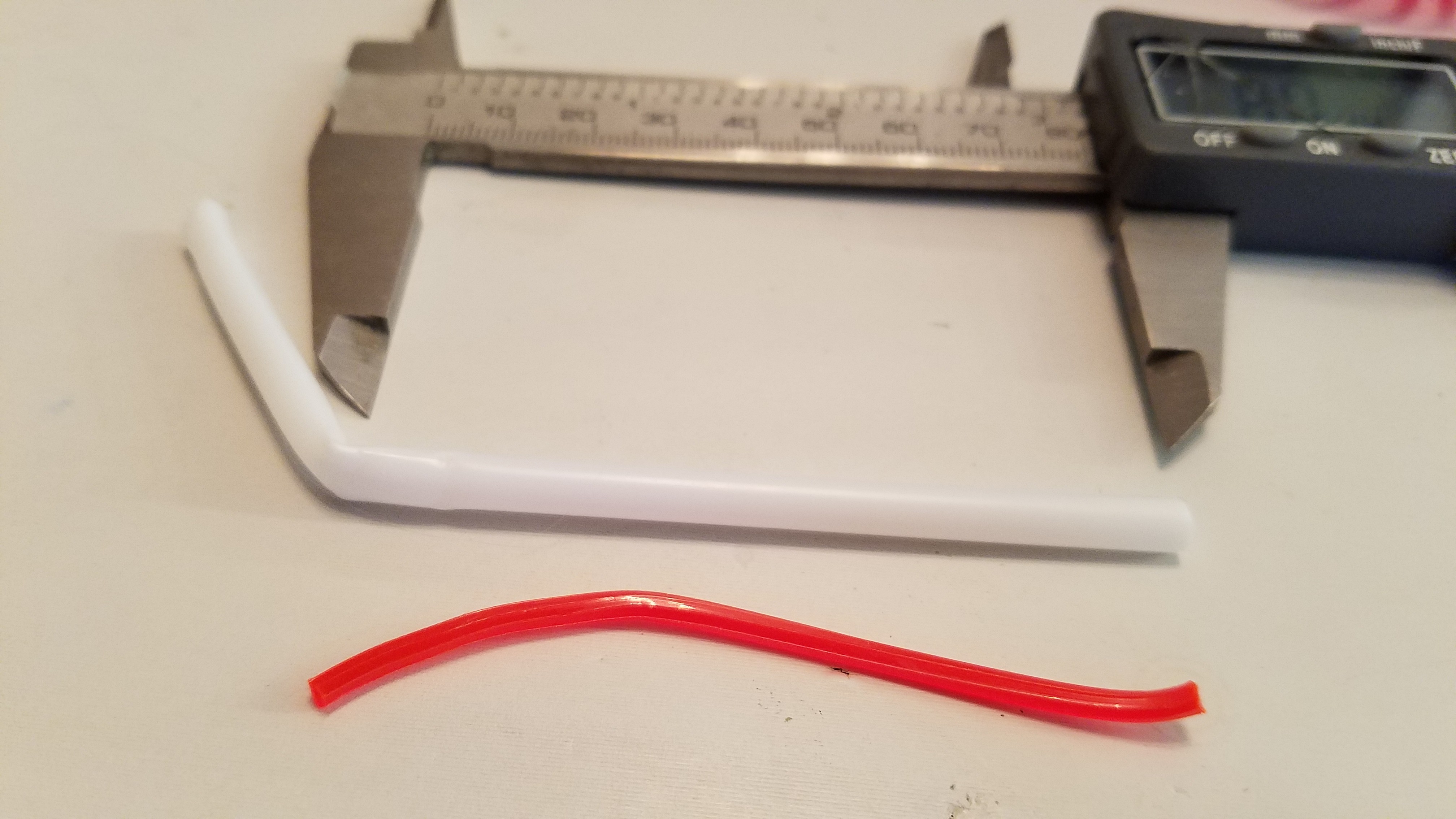
The line tended to curl as I was cutting it, which made getting 30 equal lengths a possible challenge. It also didn't help that this particular line literally came from my string trimmer as I changed out the line for some new stuff.
To solve the cutting a bunch of equal length sections problem, I came up with a simple solution of putting it inside a balloon handle (tube) bent over at the correct length, and then cutting them.
![]()
Worked well.
-
Almost..
05/02/2019 at 06:27 • 0 commentsThe space between filament pockets was a little too small. It failed to render to greater than a single nozzle_width at the base of each pocket, so the wall between them disappeared on slicing.
Tweaked the model a little. New files are up.
![]()
Then I got to battle a new issue. One of the magballs on my printer unscrewed itself a little and was driving me mad. First time in about 3 years, so I guess I was due for it.
Printing again.
-
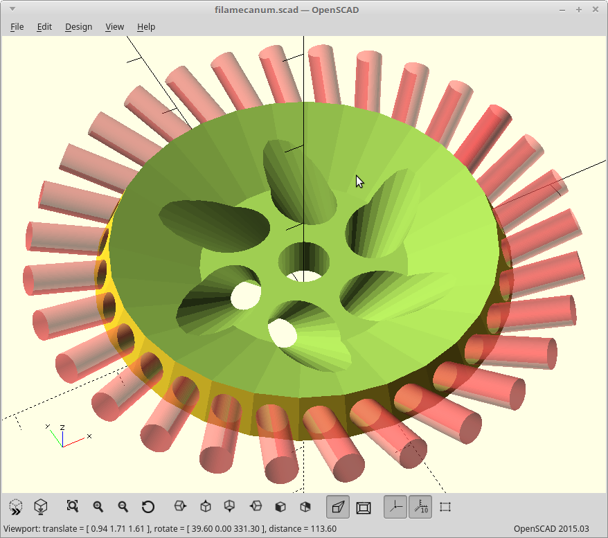
Loop size
05/02/2019 at 03:29 • 0 commentsI'm keeping everything small here to start. Actually, I think that may be a requirement.
The filament loops will want to deflect as I apply torque to the wheel. So the size of the loop needs to be just right to resist that deflection, but then still allow the loop to provide some spring tension and act as a tire.
A larger rim diameter would allow me to place more loops and spread out the off-axis force for the 'against the grain' Mecanum motion, but will also increase the force required to start the sliding motion. I totally guessed at an appropriate balance here, and so the loops are elliptical with a short radius of rim_r/1.44 and a long radius of rim_r/1.44*1.25. This balances out to a roughly spherical tire cross section though due to the angle of the loops.
The finished tire I've modeled here including the loops is about 90mm in diameter and has 30 filament loops. The filament enters the rim at a 115 degree angle, so I more or less have 3/4 of a tire circumference with the filament strands.
This was all based off some nylon line I have for my string trimmer here which has a 2.8mm diameter, but it is octagonal instead of round. The ridges on the line should enhance the grip in the off-axis direction, but still allow sliding along the length.
Or so goes the plan...
-
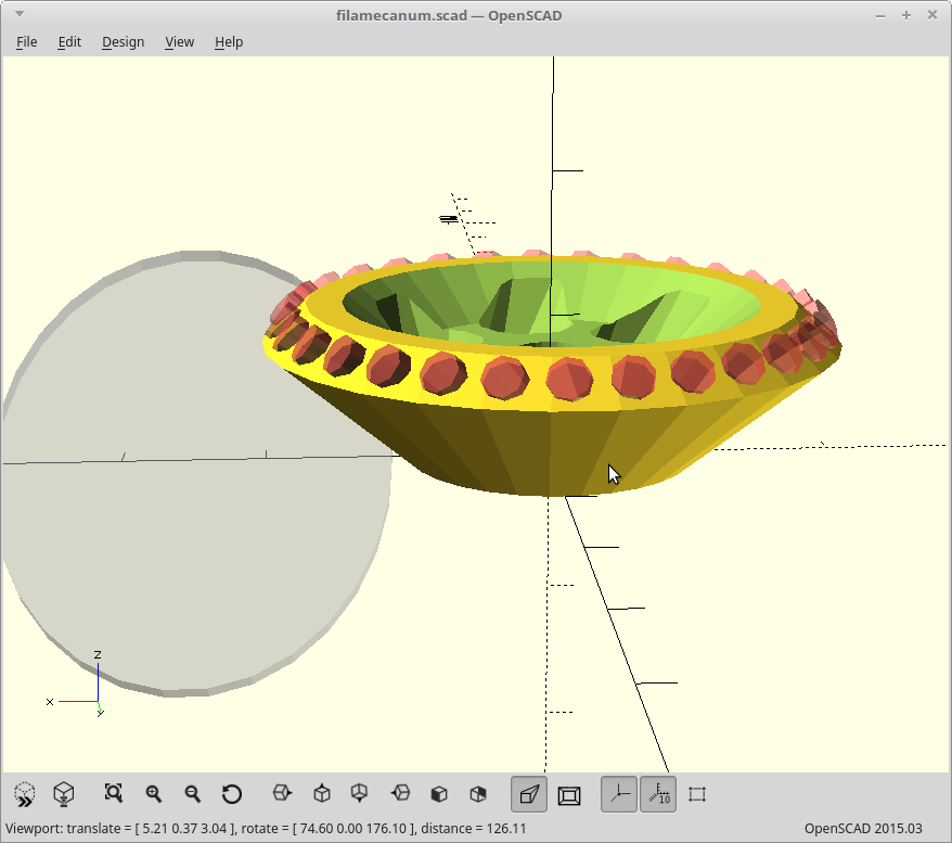
A little refinement
05/02/2019 at 00:00 • 0 commentsThe rim wasn't quite even between the top/bottom thickness around the filaments. That bothered me, so I fixed it.
![]()
I was able to programatically create the rim based upon the filament pockets themselves, but the code was a real dog and the resulting model just made me feel dirty for creating it. I went back to manually doing it, and so this is just a couple cylinders fit to where the pockets need to be. It's not parametric, but it is about 100x faster and a much cleaner model.
Perhaps I'll figure out how to determine the cylinders needed for a proper parametric model later.
Stopped the print.. printing again..
-
Actual math
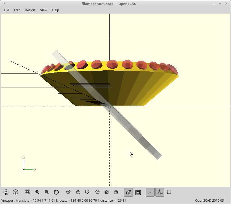
05/01/2019 at 23:49 • 0 commentsI tried a bit harder here, and did an actual translation of a filament bit starting with the desired 45 degree angle where it hits the ground.
![]()
![]()
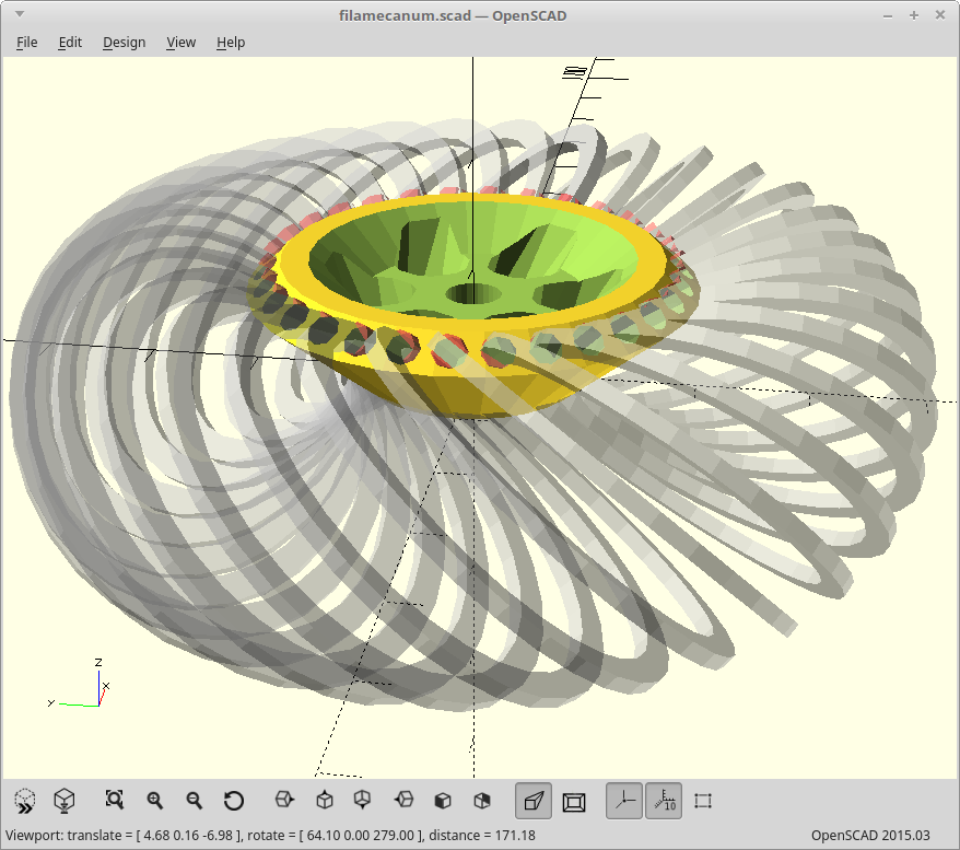
All of them together then look like this.
![]()
Yay for math!
Printing...
-
A total guess
05/01/2019 at 23:37 • 0 commentsI winged the filament hole angles, and came up with this:
![]()
Printed it.
I was way off...