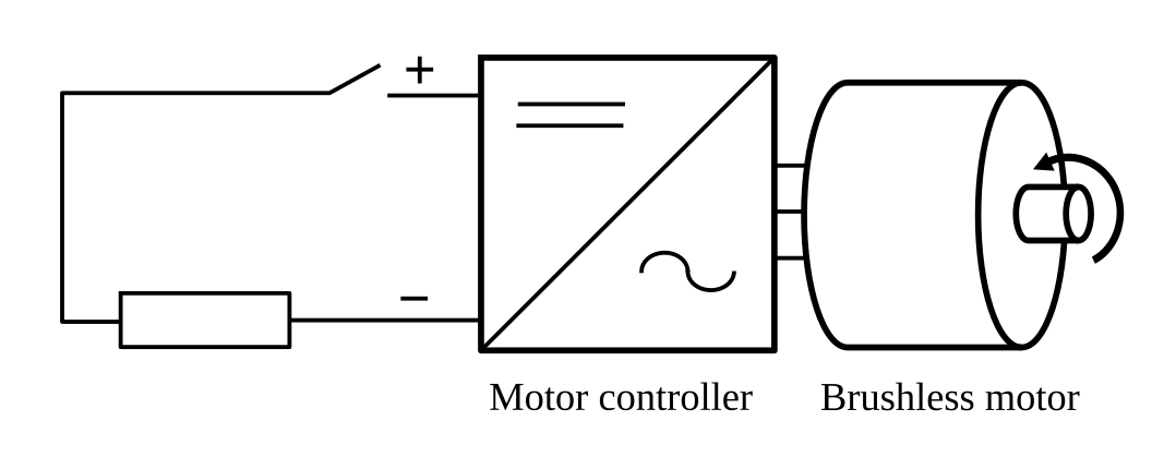
I have decided to first develop a simple DC supply voltage controller that will be the basis for two configurations described in the introduction (controller acting as a voltage source for the self sustained DC "grid"; controller connected to the grid-tied inverter).
Controller is a simple PI regulator that determines the motor torque based on DC voltage reference and measured DC voltage:

Parameters are currently set with experimentation, but there should be a simple way of defining the coefficients based on system parameters (capacitance, torque constant, rotational speed).
For the "proof of concept" test I used a simple power resistor as a load for DC supply:

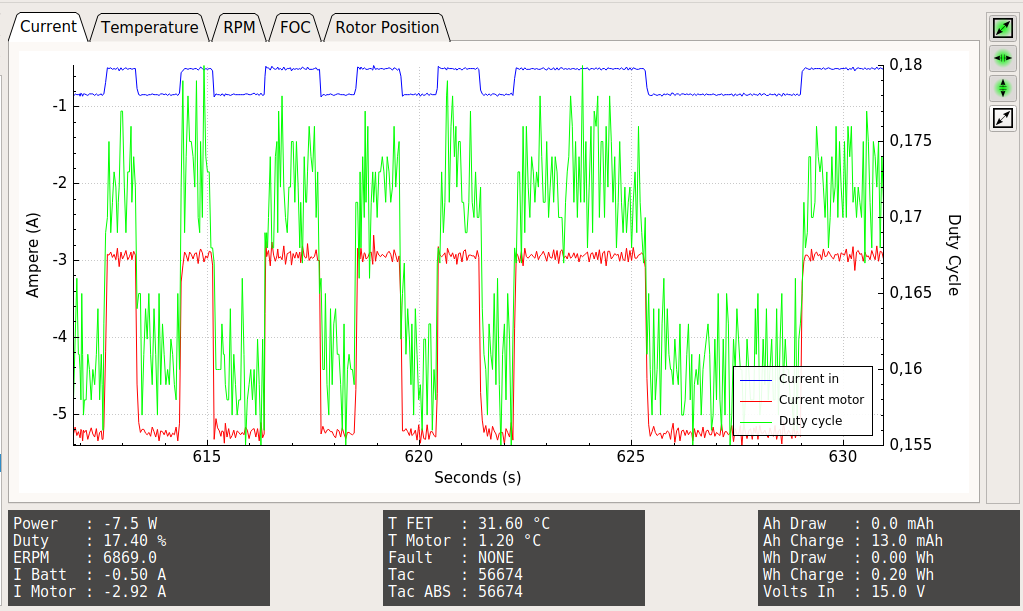
Voltage reference was set at 15 V (voltage controller running at 1kHz), while resistor was connected and disconnected multiple times. Voltage remained constant while the motor current changed according the the DC supply energy demand:

Here is a video of the multimeter and power resistor connected to the controller DC terminals:
After some additional testing I will add the support of the new mode and parameters to the PC GUI.
 Mitja Breznik
Discussions
Become a Hackaday.io Member
Create an account to leave a comment. Already have an account? Log In.