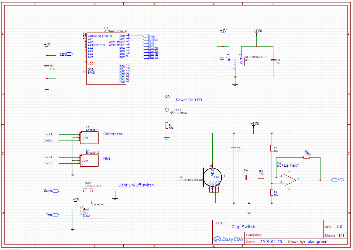
Here is my schematic, captured in EasyEDA.

Notes
- Most of these components I chose simply because I had them. They're not necessarily the best for the job, but they're close enough.
- Microcontroller: I chose the ATTiny3217. It is over powered for this application, which is fine.
- Power on LED: I wanted a power indicator to help when I was troubleshooting.
- Microphone: I used the SPU0410LR5H. I'm familiar with it, and it Just Works.
- Op Amp: MCP6281 is a solid low-voltage raill-to-rail amp. It has a 5MHz Gain-Bandwidth Product, which is 500 times what it needs in this application. The trade off for this performance is that it consumes a whole half milliamp of quiescent current, but that is not a problem in this application since it is connected to mains power.
- 1.8 V supply. The WS2812s require a 5V data signal, which means it is convenient to run the microcontroller at 5V. However, the microphone is rated at a maximum of 3.6V. I would have powered it at 3.3V, but I happened to have a large number of Texas Instruments REF3318, and no 3v3 regulators. The REF3318 is a reference rather than a voltage regulator, but it is rated for 5mA output - plenty for the microphone and amplifier.
- Switch: A generic button I found in my cupboard. Ignore the model number in the schematic.
- Encoder: I used a couple of fairly standard rotary encoders that I found in my box. I don't have the exact part number, but they all work pretty much the same.
 Alan Green
Discussions
Become a Hackaday.io Member
Create an account to leave a comment. Already have an account? Log In.