burkethos
-
What’s next?
05/11/2019 at 17:47 • 0 commentsBefore putting it into volume production I have to choose which color PCB to use and possibly change the LED from WS2812 to SK6812. They are not footprint compatible but I’ve since learned from several Chinese manufacturers that the WS2812 3535 is harder to produce compared to the SK6812 3535. Some told me that they were discontinuing the WS2812 version – not a good sign. Or, they could be trying to convince me to switch because that is what they manufacture. I still have some homework to do here.
I had the first prototype (black PCBs) ready to show at the 2018 World Maker Faire in New York. One person stopped by and liked the idea, but the large thru-hole area at the bottom for the controller board was off-putting. He suggested that the area for the controller board was too tall and would result in a clunky appearing enclosure that was at odds with the streamlined cube.
He was right. (Thank you, whoever you are!)
For the sake of appearance it made sense to let the builder mount the controller board inside the enclosure along with the power supply.
Much. Nicer. Looking.
You’d think it should have been obvious, but I didn’t see it... This minimalist shape has an added benefit: it is smaller and therefore less expensive.
Win!
I fabbed some and here is what it looks like next to Mjonir:
For the final product I may round some of the PCB corners for an even sleeker look. I may also modify the baseboard such that each LED level can be daisy-chained to other levels. Some builders may want one, large chain of 512 LEDs. Or perhaps two chains of 256 LEDs – who knows? This is a no-cost option and worth considering.
-
Preproduction prototype: How did the mods turn out?
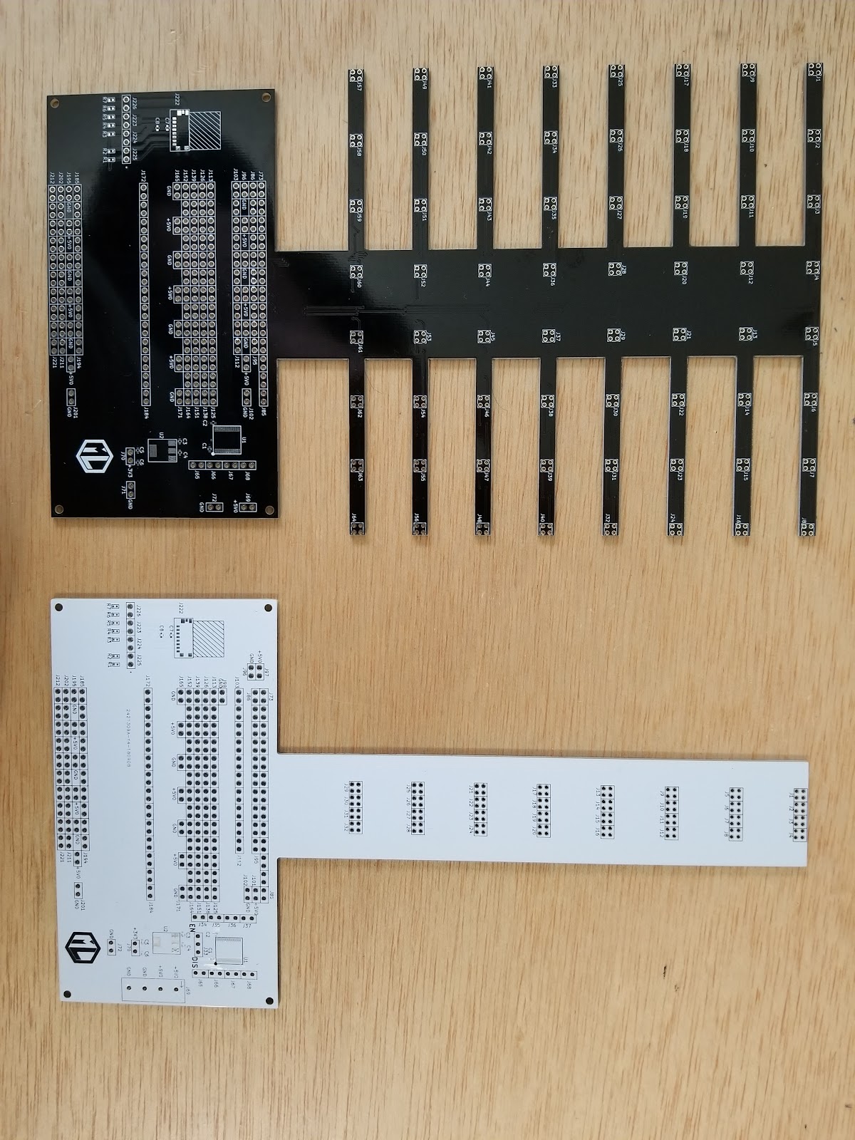
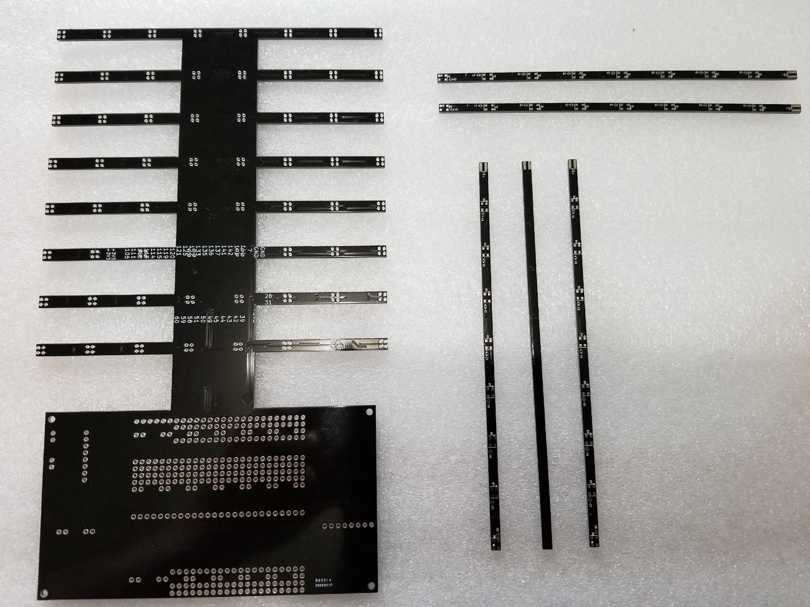
05/11/2019 at 17:45 • 0 commentsOn the left above is a single black colored 8 LED stick from the first prototype. On the right is a white colored 64 LED board from the preproduction prototype. I chose white to see how it would look compared to black, plus the LEDs I have are white.
On the left above is the prototype base board with all the fingers for the individual LED boards. On the right is Mjolnir.
The sharp eyed among you will see that I decided to add more holes for the LED boards. Instead of a 4x2 pattern of holes, I decided to put down an 8x2 pattern. I’ll do some experimenting to see how many holes I need to make a stable, non-saggy cube.
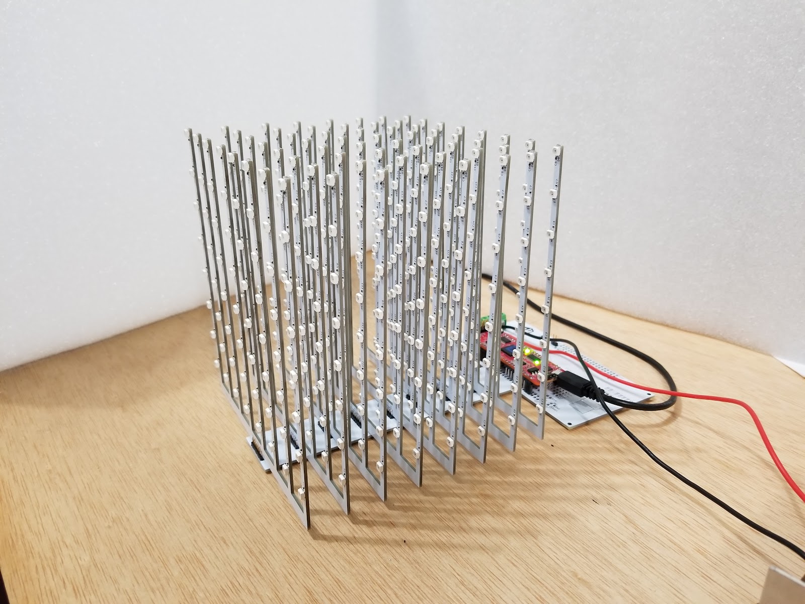
Below is a picture of a complete cube, unlit. The red controller board you can sort of see is an FPGA board using an Intel Max10 that has 5V translators built in. So, I bypass the translator on the base board. I'd say it turned out pretty well!
Ready for production, right? ...Right…?
-
Mjolnir! Revisiting the base board.
05/11/2019 at 17:35 • 0 commentsWith the fingers removed from the base board it looked like Thor’s hammer, Mjolnir. It is a simple, much-less-busy-looking design. It will keep an observer’s focus where it belongs -- on the LEDs.
Regarding controller circuits, I looked at many of the most popular controller boards -- Arduino, Teensy, Raspberry Pi etc. -- and noticed that most of them would require voltage translators to make the cube work properly. Most of the boards these days have 3.3V GPIO compatibility. A smaller number have 5V GPIO. The LEDs require 5V signal levels.
I decided to include a 3.3V to 5V level translator chip on the base board so that many controller boards can be used directly. It also became clear that there wasn't going to be an easy way to figure out which GPIO pins would be used to drive the LEDs. I figured that this should again be left to the builder using the board of their choice.
The best way to allow the most flexibility was to simply provide a sea of 0.1" spaced holes to mount the chosen board onto. The builder will then have to discretely wire their chosen GPIO to the level translator. I'll be adding in additional holes scattered around the board for+5V and GND connections to make it easier to power the chosen controller board.
Each level of the cube has its own level translator and therefore 64 LEDs per translator. Something like a FadeCandy can drive this configuration. Teensy boards are also well suited. Other board types can be made to work as well -- it is up to you to pick your board and connect it into the translators.
Holes are provided on both sides of the translator in the event that your board can already drive 5V logic directly. In other words, the translator can be bypassed.
The last major thing to be concerned with is the power supply. As we calculated earlier, a full cube at full brightness can pull almost 31 amps at 5V. But, I've noticed that I don't need to run the cube at anywhere near full brightness to get a great effect. In fact, at 10% brightness I get a great result. My first prototype was built using a 7A supply and it looks great.
Worrying about how to power the cube was another issue with many, many options to choose from. Ultimately, I decided that the easiest, most universal way to power the cube was simple terminal blocks. These blocks can accept a wide range of wire gauges and all the builder needs to do is strip wires and screw down the wire clamps. Not the least expensive option, but we're only talking about pennies of difference in connector costs and for the build volumes I envision, these are an ideal solution.
The terminal block I chose can handle up to 16A per pin so I've included two pins each for +5VDC and GND. Depending on how brightly you want to light your cube, only one power and ground pin may be required. The connector can handle the full 31A that the LEDs can draw if you choose to melt your eyeballs. I’d wear a welder’s mask at that level of brightness!
Lastly is the enclosure. You want a nice cube to have a nice case covering the controller area of the base board. I’ll be adding some plans for a simple laser cut enclosure to the repository.
-
Back to the drawing board V.
05/11/2019 at 16:40 • 0 commentsOn the one hand, the cube works brilliantly (pun intended) and looks cool. On the two hand it is a royal pain to put together. What if...
I had been clinging to the idea of having individual LED boards, but for no good reason. This was an outgrowth of my original, fully connectorized cube and perhaps some subconscious influence from seeing other cube designs. There was no compelling reason that I couldn't rethink this, so...I did.
I sketched out some ideas for combining all of the LED boards for one level of the cube onto a single PCB. I would still use 2mm headers as before, but here's the rub -- I only needed two of the 2x2 headers instead of 8. For a full cube, I now needed 16 of them for a cost of....wait for it...$2.32!
Mega win!
Well, not so fast...
I thought about it some more and figured that another way to reduce construction complexity would be to use press-fit connectors instead of soldered thru hole headers. Press-fits allow the builder to simply press the LED board assembly into the holes on the base board. No soldering required (but you can solder them as well if desired). The connector pins fit snuggly into the corresponding base board holes and would allow for very rapid assembly. An added benefit is that the boards would self-align due to the snug fit of the connector. They have the added benefit of making disassembly possible too.
Win!
Based on the first prototype build and the concern that two of the pin headers might not easily hold the weight of an LED board without sagging, I decided to add holes for 2 extra headers to the base board just in case they are needed for stiffening.
The press fit headers are more expensive and I have to look into second sourcing. If two of these are used per LED board, the total cube cost is: $7.52. I can reduce this a bit by replacing two of the 2x2 with a single 4x2 on each board for a cost of: $6.25. This represents an over 80% reduction in connector costs from the original design idea.
After lots of crumpled up pieces of paper I think I’ve found a winning combination of price and ease of construction by using press-fit headers. The builder is now faced with eight super simple solder connections per LED board. Beginners at soldering should have no problem with this.
A final benefit is that switching to a single 4x2 header meant that all the little fingers coming out of the sides of the base board would go away, leaving a more streamlined, elegant appearance.
-
First FR4!
05/10/2019 at 00:44 • 0 commentsIt was time to make a prototype so I designed both board types in KiCad. I wanted the LED board to be not much wider than the LED itself in an attempt to minimize the PCB visibility. The PCB will act as a viewing obstruction when used in a cube so keeping it as narrow as possible was desired.
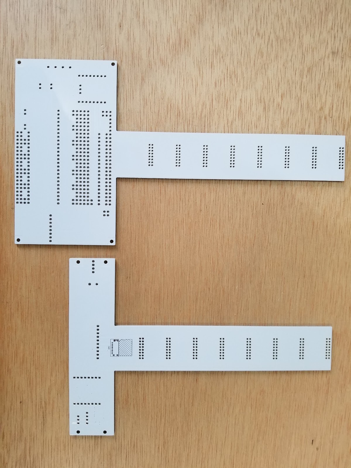
I ended up with a board .140" (~4mm) wide. This is when I hit a bit of a snag. Many of the low cost PCB fab houses have minimum dimensions on the order of .2" or .25". It took me awhile to find a fab house that could build a board as narrow as I wanted on their low cost fab lines. Eventually I found a board house and got both of my board types made in sufficient quantity to build a test cube. I procured the required components and built up a cube. The two circuit board types are shown below.
Vertical base board on the left, some LED horizontals on the right.
I mounted the vertical to some scrap wood. The controller board I picked was an FPGA board I had designed previously that incorporates an Intel MAX10 FPGA. It worked great and didn't look like anything else on the market as the pictures show.
Fully assembled cube, unlit.
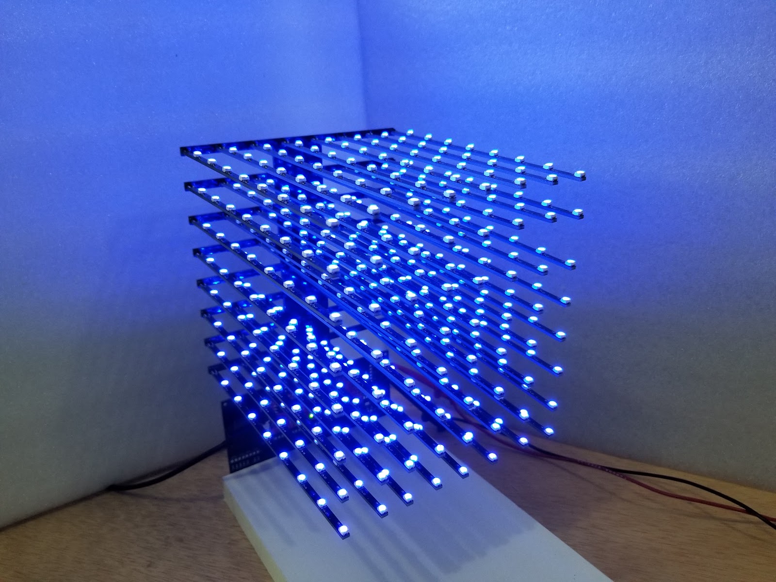
Fully assembled cube, lit blue.
But, as one of my college professors would say, this design "fell apart beautifully!"
Here is what's wrong with it: Mounting the LED boards to the vertical board so that it looks good is not easy. Yes, they just plug in and the soldering is simple. But, it is NOT easy to align them properly both across a horizontal level and then vertically from level to level. I needed one hand to hold solder, my other hand to hold the soldering iron, and a third hand to hold the LED board. The image below shows the LED board sagging a bit.
It was like juggling 64 flaming chainsaws to put it together. The holes for the LED board connectors allow the connector to move around too much. I could make the holes smaller, but run the risk that alternate source parts wouldn’t fit. It would be difficult to get it just right.
So, while the assembly part is fairly easy, making the assembly look good is decidedly not.
Heavy sigh.
I didn't want to ask the builder to jump through all kinds of hoops to try and get the LED boards properly aligned prior to soldering them onto the base board. I also didn't want to create some sort of special jig that would make the alignment process easier -- I wanted to eliminate this fiddly part of assembly completely.
-
Back to the drawing board IV.
05/10/2019 at 00:22 • 0 commentsOut came the sketch pad yet again. There had to be a way to eliminate one of the unique board types. These days we aren't overly restricted regarding the shape of a circuit board, so what if I played with the shape a bit?
What if the base board was combined with the verticals? I found that I could make a sea of holes at one end to accommodate mounting the controller board of choice. On the other end I could have an oddly shaped board with a long vertical run that had fingers coming out of each side. The LED boards could then mount onto the fingers as shown, and the controller board could mount at the other end. I was back to two unique circuit board types.
Win!
This method had the added benefit of cutting the number of 2mm 2x2 headers in half -- I would only need 64 of them now for a cost of $9.30. This is 75% less cost compared to the original sketch with all those 0.1” headers.
Sweet win!
I was very happy with that cost number and figured the base board idea could be mounted vertically with the LEDs pointing outward, or it could be mounted flat with the LEDs pointing upward. Two different construction styles possible with one simple circuit board.
Win!
-
Back to the drawing board III.
05/10/2019 at 00:09 • 0 commentsI wanted something fairly easy to assemble so that the focus would be on generating cool blinky content. The goal of any blinky lights project is to, well, blink lights.
This got me onto another tangent -- how to control all the LEDs? Some kits require that you provide a controller yourself, others have controllers built into the kit somehow. I really didn't like the idea of being stuck with somebody else's idea of a controller. I have my own ideas, thankyouverymuch, and I'm sure everyone building a cube has ideas of what they like too.
I now added a new goal to the cube design: allow the purchaser to control the cube using a controller board of their choosing.
An immediate advantage to this is that I no longer had to pick a method to control the LEDs. Let's face it. Regardless of the controller architecture I picked, some would like it and some would hate it. Why not pick your own? Similarly, my product would not have the added costs associated with controller circuitry. This would reduce the kit cost.
Win!
At this point I was fresh out of ideas and did what many a product developer does -- put the design on the back burner and move onto other things. I gave myself a rest and let ideas continue to percolate through my subconscious.
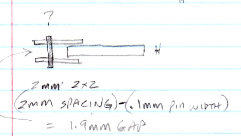
The cube design came to the surface again when I was looking at 2mm male pin headers for something else. I was specifically looking at headers with 2 rows of pins instead of just a single row of pins. While looking at the mechanical drawing of a header I noticed something. The space between the two pin rows, with the width of the pins subtracted, was just a bit bigger than the width of a .062" PCB.
Out came the sketchpad again and I came up with this:
The thickness of the PCB plus the added thickness of the copper plating *should* fit between the rows of the 2mm header. This was using the header in a non-standard way and would require hand soldering. But, some soldering is OK in an electronic kit and this was easy soldering.
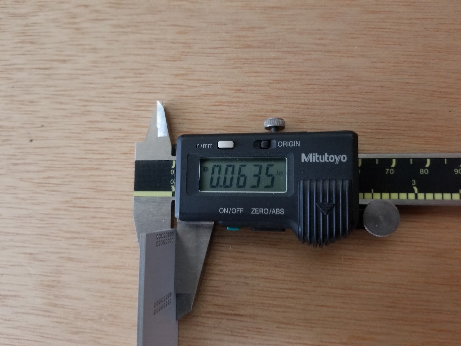
I had some old .062 circuit boards lying around and could measure their finished thickness using calipers. It looked very promising
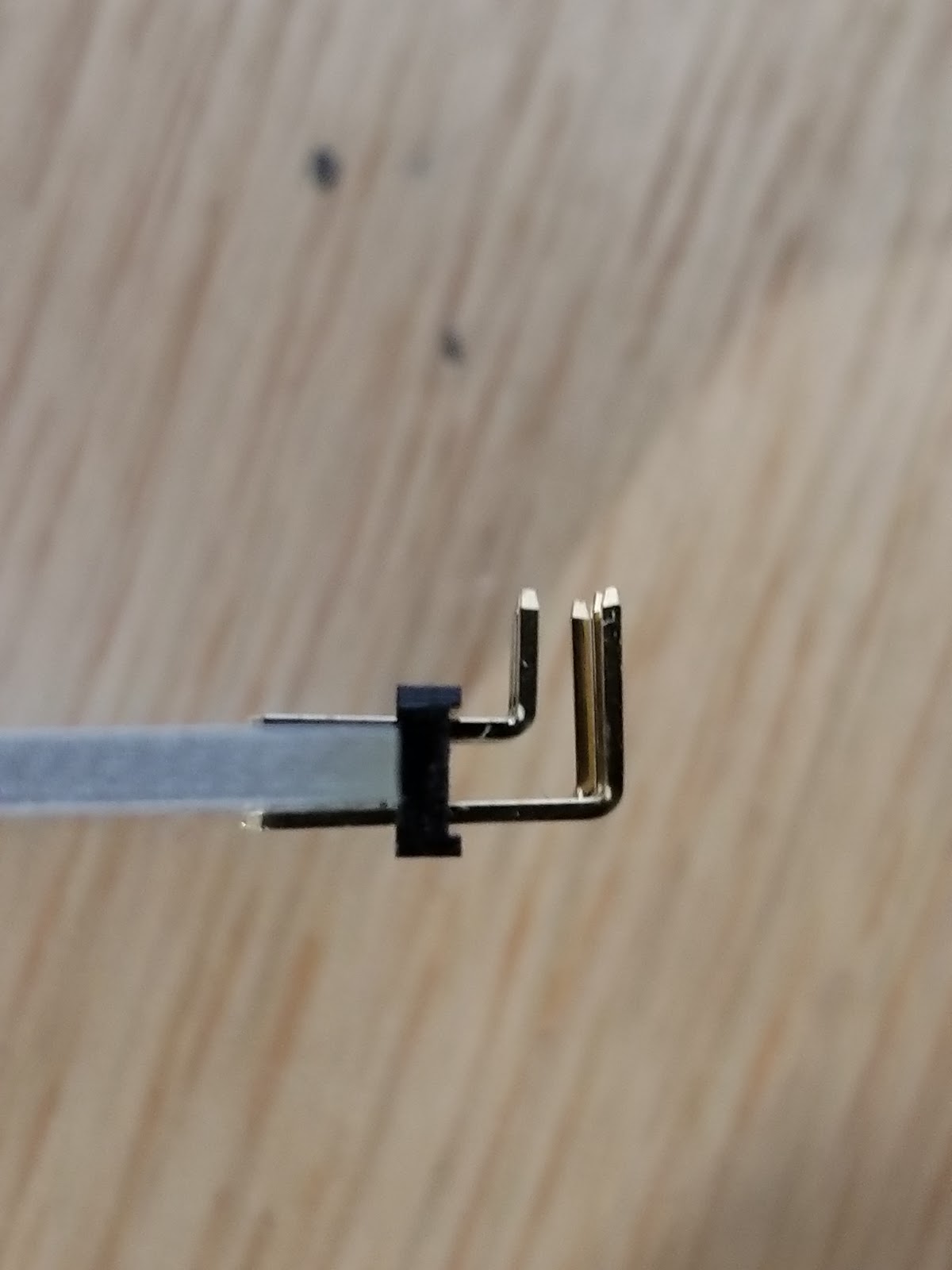
I scrounged some 2mm 2 row headers and viola'! Fits beautifully.
Another trip to Digi-Key found 2 row male headers, 2mm spacing, unshrouded, 2 rows, 4 pins, pre-cut to size = $.31 qty 1, and $.145 qty 1000.
Note: Digi-Key and Mouser are your best friends when developing products.
If I used the original horizontal LED board plugging into vertical PCBs, then I'd need 128 of these connectors per cube = $18.60. I’ve cut the connector cost in half, which is nice and all, but I was back to needing three unique circuit board types: vertical, horizontal, and base.
Hmmmm....
-
Back to the drawing board II.
05/09/2019 at 23:46 • 0 commentsI started kicking around ideas for eliminating all the connectors completely. If I went back to the idea of stacked, horizontal LED boards, I could just put some via holes at each of the board and stack them using rigid wires. These wires would have to be hand soldered and the power and ground wires would have to be suitable sized to carry the worst case current load.
While this might look slick, the amount of hand assembly was onerous and I'd have to come up with some sort of jigs/spacers to keep the boards at the correct separation to make a cube. I think this is certainly achievable but I ultimately rejected it as being too complicated to assemble.
-
Back to the drawing board.
05/09/2019 at 23:45 • 0 commentsSo, I went back to my pencil and paper and sketched out a completely different idea using what are called edge connectors. This connector type would be mounted vertically on a base board and each LED board would plug into a connector. In effect, the LED boards would become "verticals" and the number of unique circuit boards would reduce to two -- the LED board + the base board.
Win!
A few years ago the folks at Looking Glass created an 8x8x8 cube kit, the L3D, using a technique like this. They had a decent Kickstarter campaign for it: https://www.kickstarter.com/projects/lookingglass/l3d-cube-the-3d-led-cube-from-the-future but it appears they no longer produce this item.
The way this works is by etching signal pads on the LED boards directly -- no separate connector is need on the LED boards. These signal pads would then make contact with the edge connector pins when the LED board was inserted into the edge connector. The total number of connectors would reduce from 256 down to just 64.
Win!
And it would be simpler to assemble.
Win!
Then I looked at the cost, searching on Digi-Key for "Card Edge Connectors." For this type of connector I would need 4 pins: +5V, GND, serial data in, serial data out. Edge connectors connect to both sides of the PCB when the PCB is plugged in. Therefore, I would need two pads on the top of the PCB and two pads on the bottom of the PCB.
I narrowed my search to board thickness of 0.062", the most common PCB thickness and also the least expensive to manufacture. I found a nice little connector, but it only had one supplier -- that is a warning flag. What if you can't get parts when you need them? There isn't a second source. Add to this the fact that single piece pricing is $2.41 and 1000 piece pricing is $1.60. Even at 1000 piece pricing, 64 of these = $102.40.
Way. Too. Expensive.
-
Flash of brilliance! Or maybe a flash of stupid…
05/09/2019 at 23:35 • 0 commentsGetting back to the product design, I now have constraints to work with and the major component of the product (WS2812) determined. Now comes the fun part! Now is when I take out plain old pencil and paper and start sketching ideas. This is by far – for me -- the fastest way to iterate designs, bar none. Using pencil allows me to quickly sketch and modify ideas. It requires zero electrical power and can be done anywhere an idea strikes you.
I can quickly discard ideas as impractical and move on. Once my ideas are solidified I move them to the computer.
So what did my first sketches look like? My first inclination was to try to minimize the amount of soldering required to build the kit. Maybe even eliminate it. The only way I could think of to eliminate it and still have a three dimensional object was to use connectors.
Lots of connectors.
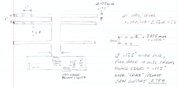
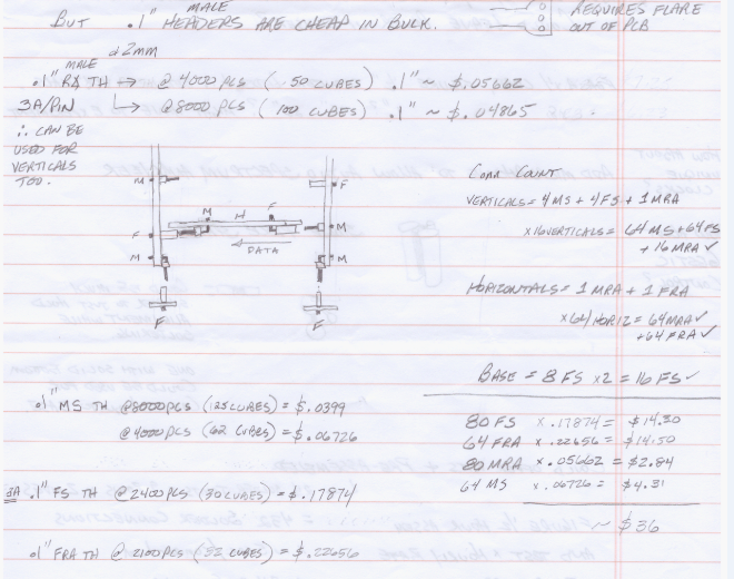
I would need a small, thin circuit board for the LEDs. These would be mounted horizontally and stacked vertically. In order to stack them, I'd need small, thin boards on each end of the horizontal LED boards. These vertical boards would have to mount into some sort of base board that handled connections to the outside world, LED control, and power distribution. It looked like this:
On one end of each horizontal was a connector for power, ground and serial data input. On the other end of the horizontal was a connector for power, ground and serial data output. I could polarize these connectors such that they could only be plugged into the verticals one way -- it would eliminate the possibility of plugging the horizontals in backwards which could potentially destroy the LEDs.
Win!
Each vertical would then have the appropriate mating connectors as well as connectors to plug into the main board.
A little more thought and I realized that with a connectorized solution, I could actually make the cube expandable, or perhaps even allow non-square shapes. For example, stacking two vertical boards would allow an 8x8x16 cube to be built. I just had to ensure that the connectors and power planes were capable of handling more current than just an 8x8x8 cube.
Win!
Now for the type of connector. Many a designer will curse at the mention of connectors, myself included. They can be one of the most unpleasant aspects of a design to contend with. Frequently the perfect connector doesn’t exist, or it is unobtanium, or uber-expensive. Ugh. Connectors suck.
In an attempt to keep it simple, stupid (KISS), my first thought was pin headers. There are many suppliers so second sourcing should be easy. Headers come in both genders and in a variety of pin pitches so that it should be fairly easy to find what I needed. They are ubiquitous.
A horizontal board needed to handle current for eight LEDs and potentially more if multiple horizontal boards are connected together. At 60 mA per smart LED, times 8 LEDs, this works out to .48 A per horizontal. Each vertical therefore needs to handle 8 (or more) horizontal boards, so the verticals need to handle at least 8 x .48 = 3.84 A.
Referring back to the sketch, each horizontal input end would need +5V power at 0.48A, a ground connection and a serial data input signal = 3 pin connector. The opposite polarity of that connector would be needed to plug the horizontal into the vertical board.
One vertical cube assembly would be comprised of 8 horizontal boards plus 2 vertical boards. Each horizontal would require one 3-pin male header and one 3-pin female header. Each vertical would require 4 male headers and 4 female headers for the horizontal boards. The verticals would also need a connector to attach to the main board.
The total number of connectors for a vertical assembly works out to be 16 male + 16 female of the 3-pin headers. Don't forget the 2 male and 2 female headers connecting the verticals to the base.
A x8 cube requires 8 vertical assemblies, so the full cube connector totals are 128 male + 128 female of the 3 pin headers + 16 male and 16 female headers connecting the verticals to the base.
This is a lot of connectors....
Let's see what they will cost us using Digi-Key pricing. Note: regardless of the component supplier you are using, always try to search for parts that are "active" (not obsolete etc.) and "in stock" (readily available and not on allocation). I searched for both male and female headers, first looking at the most popular size, i.e. 0.1" pin spacing.
This brought up yet another thing to consider. With headers you can buy them with exactly the number of pins you need or you can buy them in longer lengths in a "breakaway" style. Breakaway headers require you to cut them into the desired length. Buying ones the exact size you need tends to cost more as the supplier or manufacturer is cutting them to length for you. This is called a "value added" operation. You can save money on a per-header basis by purchasing the longer breakaway sizes and cutting them yourself. But, the time you take to cut them has to figure into your COGS number.
Always remember: Your. Time. Isn't. Free.
Another thing to consider is aesthetics. My personal experiences with breakaway headers is that it is hard to get clean cut edges when I cut them myself. Pre-cut headers generally have clean edges which are more aesthetically pleasing.
Back to header pricing. I searched Digi-Key for rectangular connectors, header male pins, unshrouded, 0.1" spacing, single row, 3 positions. Filtering on these selections left me with still more decisions. Did I want through hole or surface mount components? Surface mount has the benefit of allowing reflow soldering techniques to be used for everything, i.e. LEDs + capacitors + headers.
On the other hand, surface mount (SMT) headers are more expensive than thru hole headers. On the other, other hand, thru-hole headers would require wave soldering in addition to reflow, so assembly would cost more.
For now I chose thru-hole with the hope that the added wave soldering costs would be less expensive than the added cost of SMT headers. Or, as a DIY kit to assemble, the customer could do the connector soldering.
I also realized that I need some connectors to be right angle and some to be straight. Recall from the sketch that the horizontal connectors are all right angles whereas the vertical connectors are all straight. My connector needs for a vertical assembly are now revised to be:
(8 x male right angle) + (8 x female right angle) + (8 x male straight) + (8 x female straight).
For a full cube this works out to: 64 male right angle + 64 female right angle + 64 male straight + 64 female straight.
The least expensive pre-cut, 3 position, male, thru hole, straight headers cost $0.10 quantity = 1, and $.0252 at quantity = 1000. Clearly volume pricing matters.
Quantity 1000 would be enough connectors for 1000/64 = 15.625 cubes.
The least expensive male right angle connector = $.18 @ qty = 1, and $.0896 @ qty = 1000.
The corresponding costs for the straight female headers = $0.36 @ qty = 1, $.17162 @ qty = 1000.
The costs for the right angle female headers = $0.50 @ qty = 1, $.2552 @ qty = 1000.
Tip: The low quantity pricing factors into your prototyping costs which factors into your COGS. In effect, you are amortizing the cost of your prototypes over the number of production units you sell. Larger quantity pricing is for volume production pricing which helps determine retail price.
Adding them up for 1000 piece pricing shows:
64 male straight: 64 x .0252 = $1.61
64 female straight: 64 x .1716 = $10.98
64 male right angle: 64 x .0896 = $5.73
64 female right angle: 64 x .2552 = $16.33
$34.66 (In my sketch I estimated ~$36)
When you factor in assembly costs and profit margin, this is expensive. I didn't bother to look into pricing surface mount connectors because in each instance they were substantially more expensive compared to thru-hole parts.
A quick look at the datasheets indicates that each header pin can handle 3A of current so these would be sufficient for the .48A required of each horizontal. In fact, several horizontals could be connected together and still remain under the 3A current limit of the pins.
Then I realized that 0.1" spacing was actually too wide for my intended use. I was using 3.5mm (.138") LEDs. A 3 pin 0.1" header was 0.3" wide (7.62mm). D'oh! This would require horizontal board that was 0.3" wide, i.e. more than twice as wide as the LED, or at the very least a thinner board that flared out at each end to accommodate the wider connectors.
Aesthetically displeasing. <cue the sad music>
So I recalculated connector pricing based on using pins spaced 2mm (.079") apart. These would be not quite as aesthetically displeasing.
At 1000 piece quantity pricing, the 2mm connector pricing is:
64 male straight: 64 x .09 = $5.76
64 female straight: 64 x .2851 = $18.25
64 male right angle: 64 x .1206 = $7.72
64 female right angle: 64 x .4521 = $28.94
$60.66
Oddly, the smaller connector that uses less raw materials to manufacture costs almost 2x what the larger connector costs. Perhaps it is due to the popularity of 0.1" headers and what I presume to be much higher production quantities.
Tip: When looking at pricing, sometimes the component with the lowest cost single piece price has a higher volume cost price compared to components with slightly higher single piece prices. Don't just assume that the lowest single piece price will produce the lowest volume price. Compare several of the lowest cost single piece prices to see which has a better price in volume.
At this point I started to question the validity of a fully connectorized design approach. I had hoped to have the LEDs be the major component cost driver of the cube. If every other component was much lower in cost, the price of a cube could be compelling. But, it seemed to me that if the connectors cost as much, or more, compared to the LEDs, then the overall cube cost was going to be too large.
Clearly NOT a flash of brilliance...

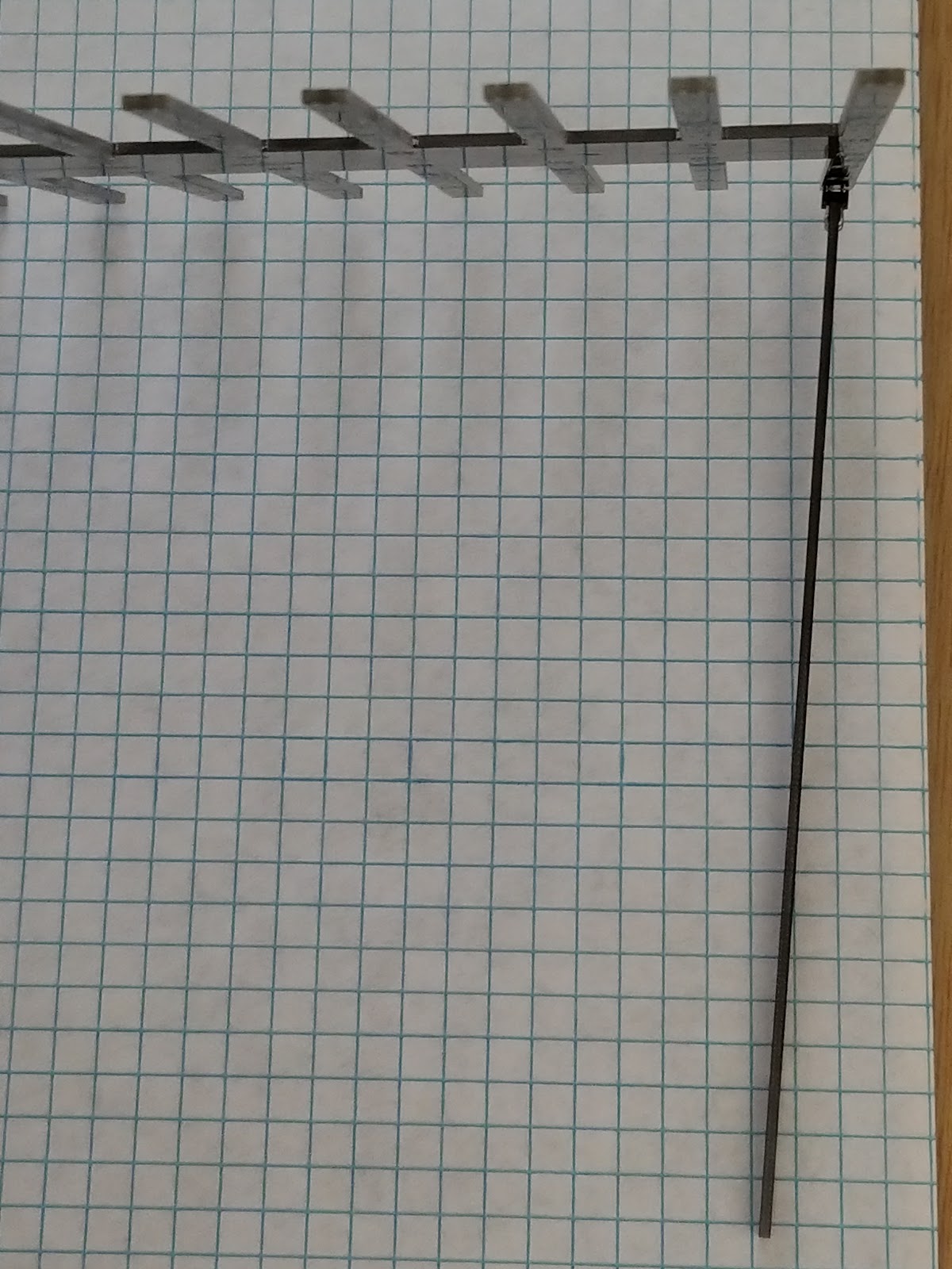 It was like juggling 64 flaming chainsaws to put it together. The holes for the LED board connectors allow the connector to move around too much. I could make the holes smaller, but run the risk that alternate source parts wouldn’t fit. It would be difficult to get it just right.