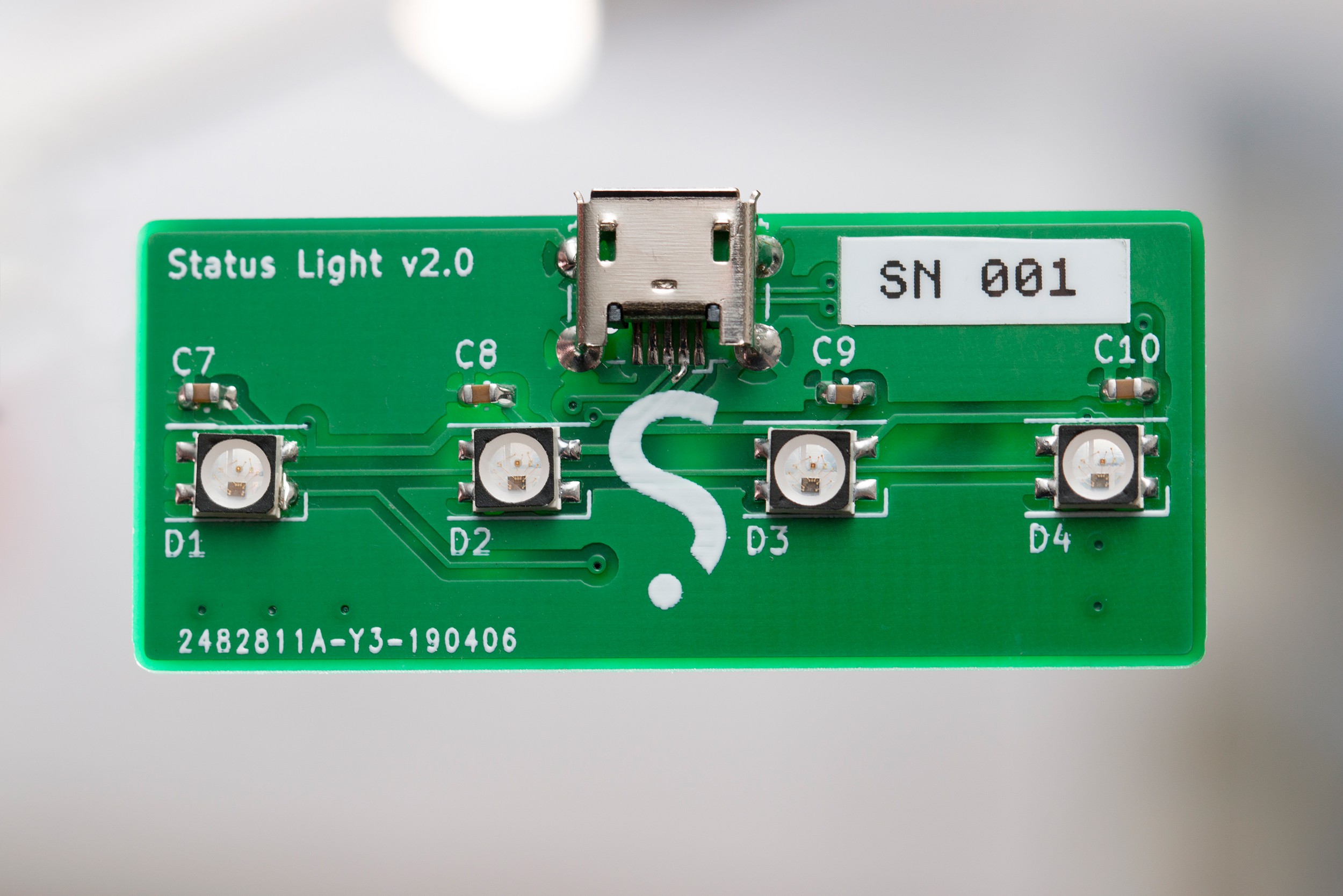
At 10pm on a Thursday evening in early April, it suddenly seemed like a great time to make another version of the status light I've been using for the last few years. Something small, simple and fun. Why not chuck together a schematic and a start a layout before calling it a night!
I'd been eyeing the STM32F070 for another project needing a basic, low-cost controller with a USB peripheral built in, and that seemed to fit the build here too. Sure, an ATTiny85 with V-USB is a little cheaper, but the options the STM32 brings to the table are worth the premium:
- 6KB of SRAM, plus a dedicated 1KB buffer for the USB peripheral
- 32KB of flash
- More capable timers (five of them)
- More I/O in a similar footprint thanks to a smaller pitch package
- SWD interface for debugging, making debugging a simple experience vs debugWIRE on an AVR. With AVRs lacking a PDI or JTAG interface I usually avoid using the debugger unless I absolutely can't solve an issue by code analysis.
Most of these are overkill for a device that controls a handful of addressable LEDs, but the smooth remote debugging experience is probably worth the cost alone. The STM32 does need 3.3V regulation, but the part count is reduced overall compared to the V-USB approach.
Schematic
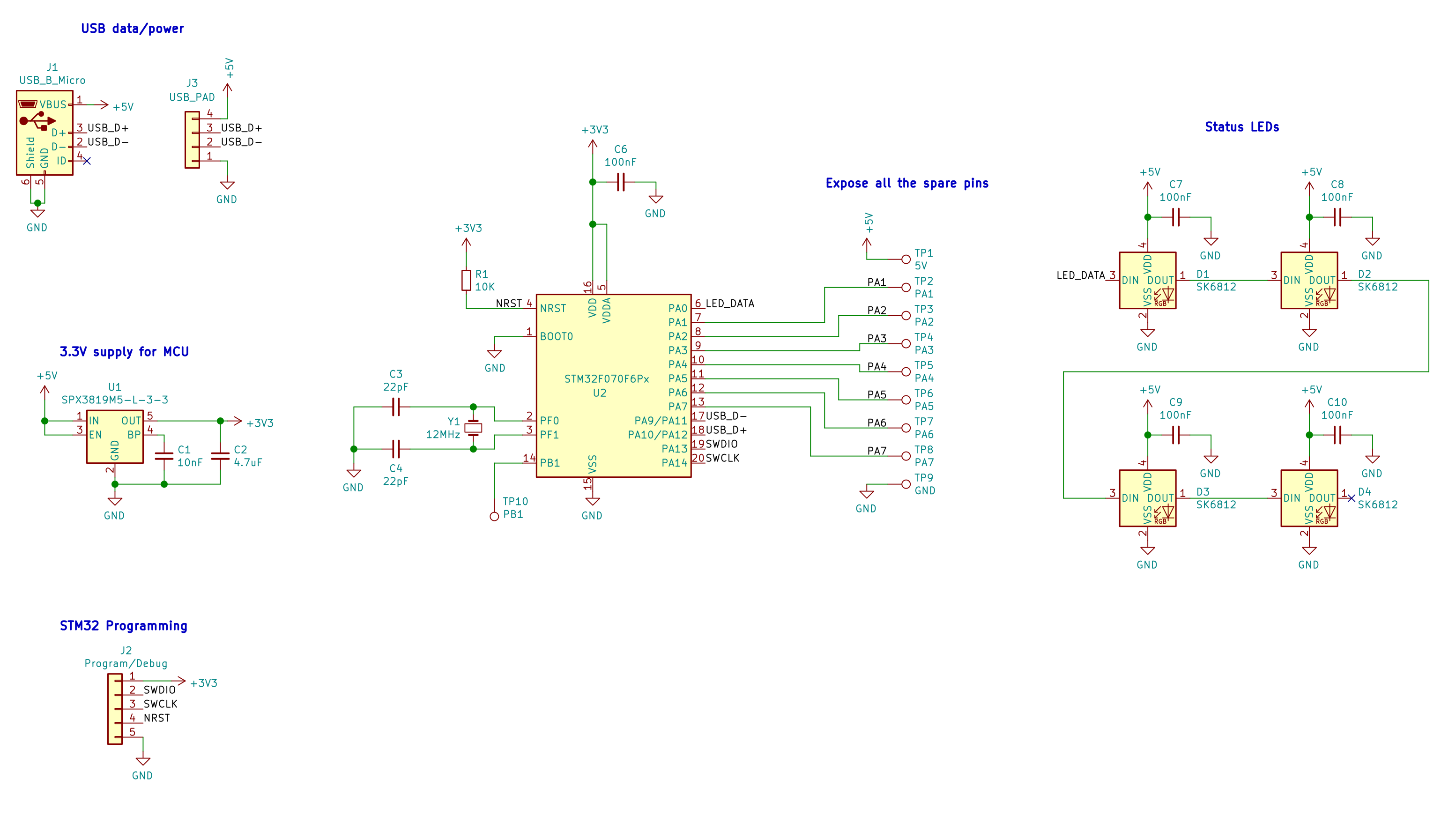
There's not a whole lot to this piece of hardware. All of the spare pins on the micro are broken out so this can be used as a mini dev board for other devices that need USB control.
A few notes for next time:
- I somehow managed to slip a pull-up resistor onto the reset line of the STM32 and sent that to the fab, even though I'd read the datasheet that states there's a built-in pull-up and only suggests adding a capacitor to ground. This is not needed.
- My 11pm-brain failed to put much thought into which pins might be better than others and just picked the first available pin (
PA0). This is fine for bit-banging the LED data signal, but on this MCU model (C6),PA0has no useful special function! An SPI or UART peripheral could've been used to encode the SK6812's time-based signal as bytes and sent via DMA instead of blocking for 115uS, but it's not a big deal for this project. - Using the USB peripheral on this chip requires the pins for both of the onboard I2C peripherals, so no hardware I2C is available on the broken-out pins. This isn't needed for the lights and can always be implemented in software if needed, but it's worth noting as a limitation of this chip when using USB.
- Putting a jumper or button footprint on the BOOT0 pin as a default would be helpful. I tied this to ground as I wasn't planning to use the built-in USB firmware upgrade mode myself, but as I'm planning to share these devices with people at my workplace that might've come in handy for letting someone upgrade their own firmware easily without requiring a J-Link/ST-Link.
PCB layout
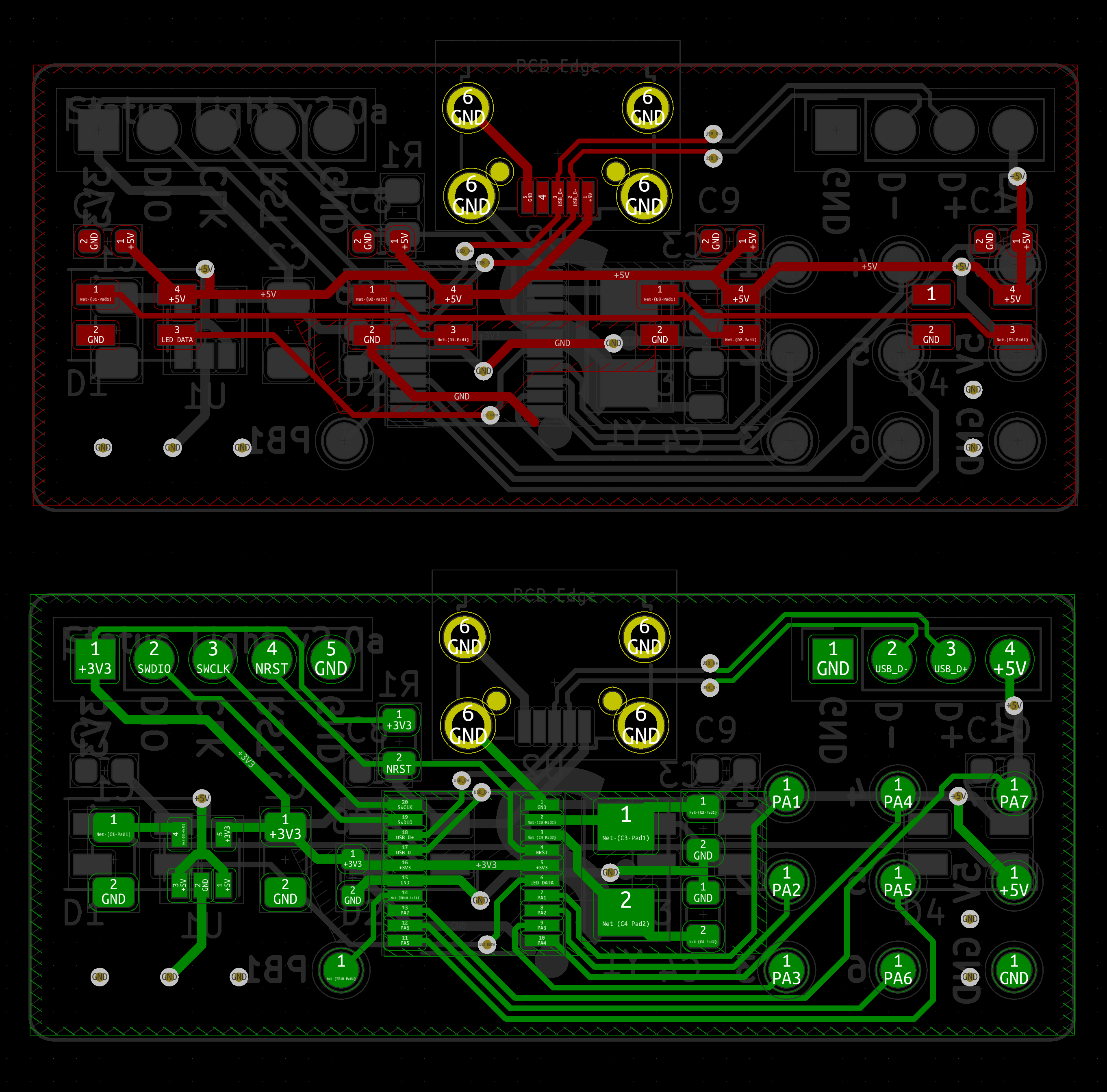
Again not much to see here. The pictured layout is slightly improved over the design that went to the fab - "2.0a" fixes an unnecessarily long ground return path for the crystal, though this hasn't caused any issues in the boards I had made so far...
I'd previously bought all of the components needed for this build, so I sent the board off and moved onto other projects while waiting. The PCB manufacture only took a couple of days, but the standard-post shipping I chose took significantly longer.
Board bring-up
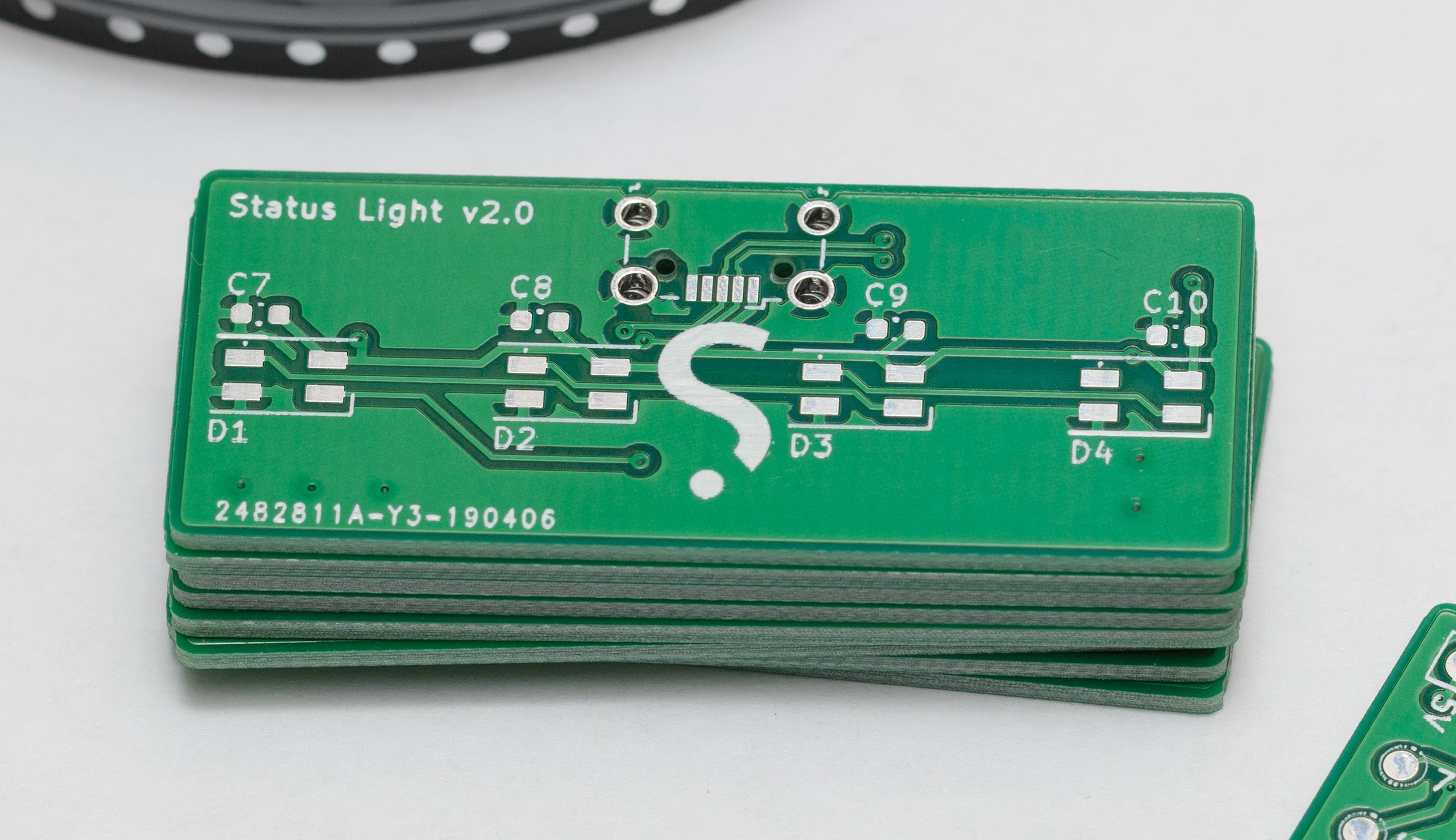
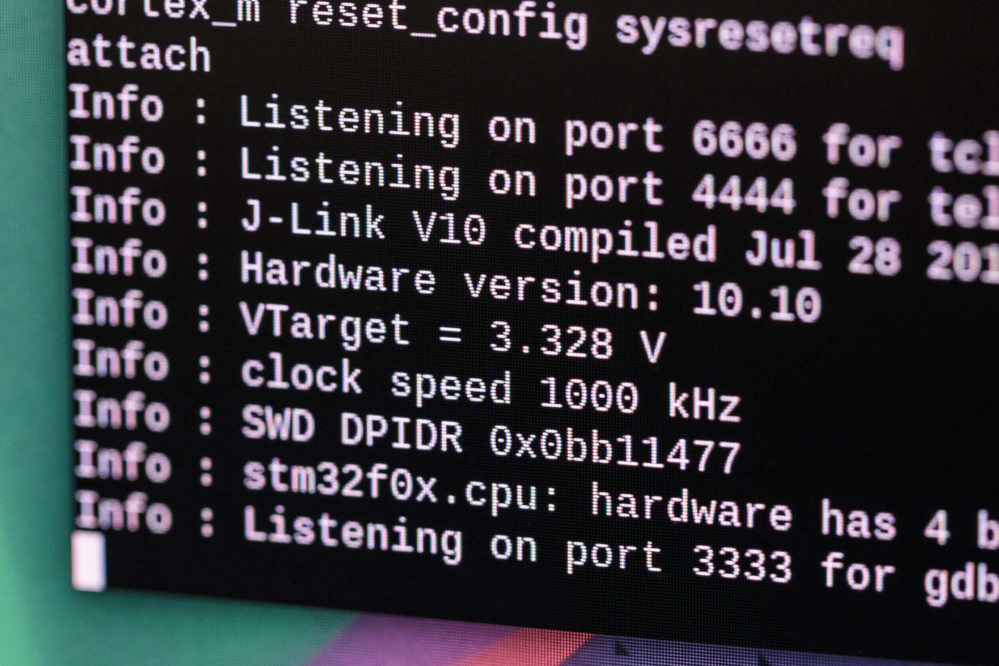
Three weeks later, the PCBs arrived and I spent an evening at the bench soldering. Assembly went fairly smoothly, with the regulator installed and tested first, then the STM32 installed and confirmed accessible over SWD:
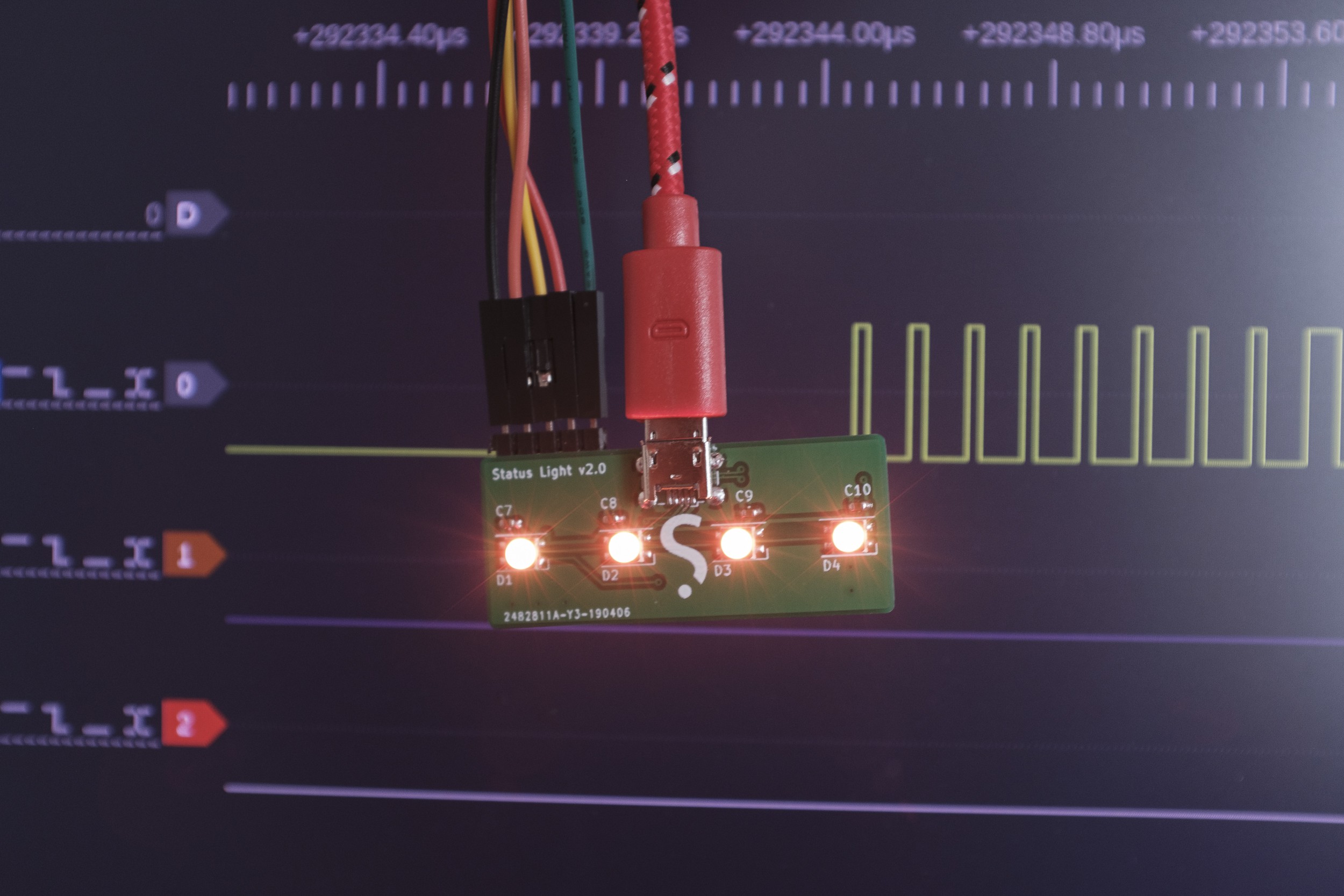
The SK6812-mini LEDs went on, and toggling their data pin as fast as possible confirmed they were all working at full brightness. A little NOP wrangling later, the correct time-based data signal could be sent and the LEDs were ready to work. The encoding has slightly different timing than the WS2812(B), but it's the same concept.
The first issue arose when the board wouldn't communicate over USB, with dmesg reporting something along the lines of "device not accepting address". While trying to confirm the crystal was operating at the expected frequency I somehow managed to destroy the oscillator circuit in the chip I was using (just by probing it?), and from then on that chip would hang waiting for the external oscillator to start, even when the STM32 was completely removed from the circuit.
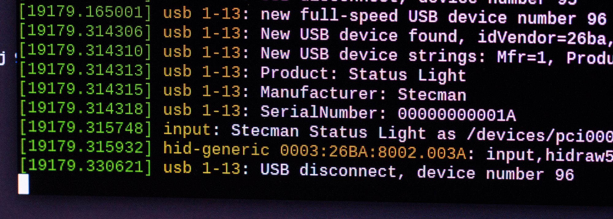
After replacing the crystal and MCU, everything worked correctly and a basic USB HID device was registering correctly with the host:
Basic USB device firmware
A simple USB device is fairly straight forward conceptually - configure a bunch of endpoints that can be polled by the host to read data, or interrupted by the host to write data. Combined with the semi-documented STM32 USB device library + HAL though, I was in for a fun time.
I won't bore you with the gory details, but after three long evenings of reading, digging through the example code and complaining about ST's code quality, and almost bailing to use libopencm3 I had an endpoint that I could send colour data:
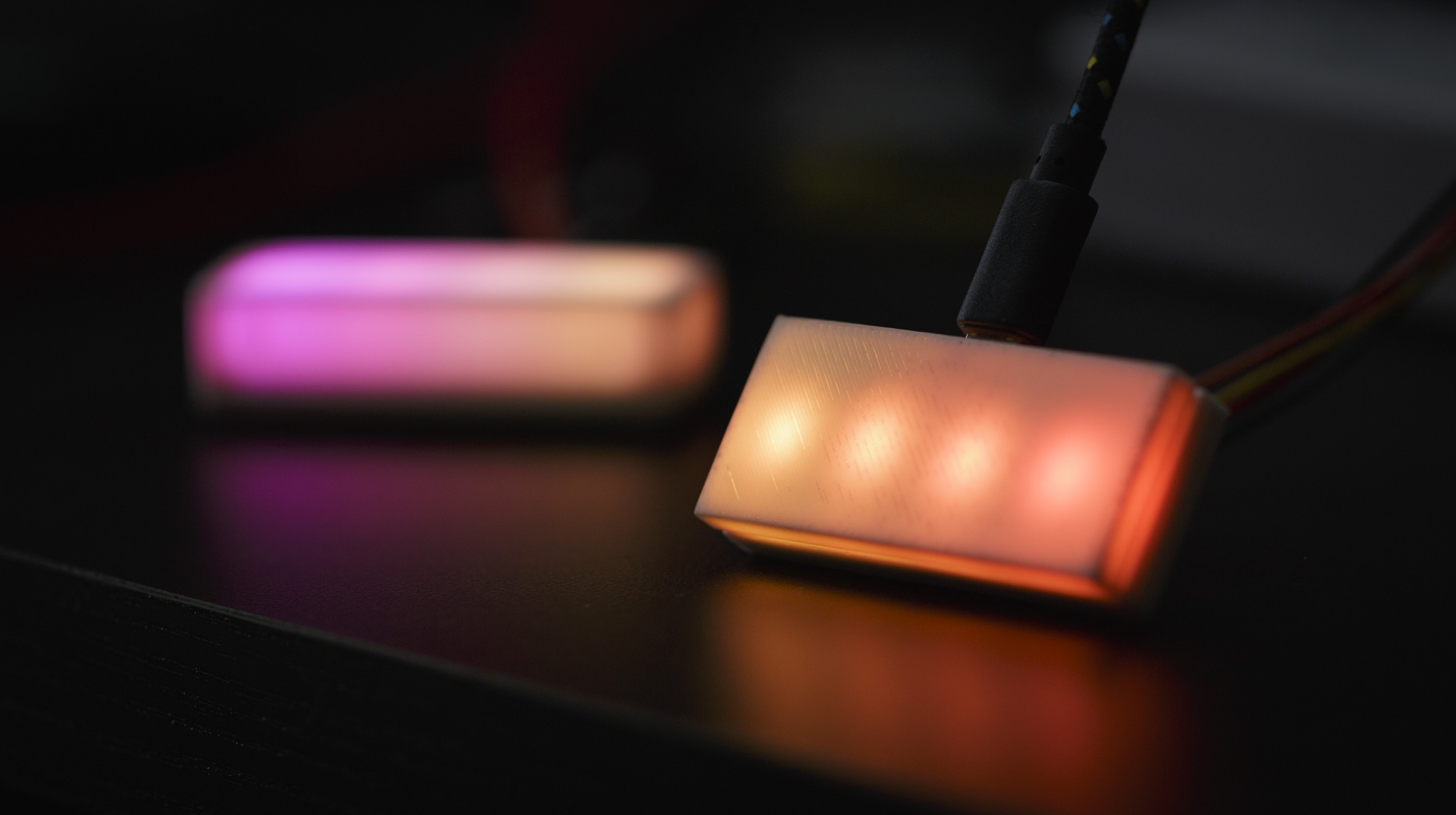
Continuously piping new colours to the device to animate works as a demo, but it's not ideal. The next step is to offload most of the work to the device and provide an interface for programming changes and animations:
- Immediately set the colour of all or some LEDs
- Transition to a colour
- Hue-shift to a colour
- Program a series of frames/commands
- Play a configured series of frames/commands (once, N times, forever)
- Program the USB disconnect and connect behaviour (eg. host going to standby)
The host side of this will be implemented in a Python library, since libusb1 makes the host side super easy:
with usb1.USBContext() as context:
    handle = context.openByVendorIDAndProductID(VENDOR_ID, PRODUCT_ID)

    if handle is None:
        print("Failed to find a device")

    with handle.claimInterface(0):
        handle.interruptWrite(1, bytearray(...))
 Stephen Holdaway
Discussions
Become a Hackaday.io Member
Create an account to leave a comment. Already have an account? Log In.