Close
0%
0%

HotOrNot Coffee Stirrer

A smart Beverage Stirrer to notify when it is safe to drink without getting singed.

Similar projects worth following
The inspiration for this project was my own. I tend to drink tea too fast, and get singed or burnt in the lips or the the tongue and then have to wait for a while for the tea to cool down.

Recently, there was a research that pointed a relation between drinking hot tea and esophageal cancer. Here is the link to the original paper https://onlinelibrary.wiley.com/doi/full/10.1002/ijc.32220
https://edition.cnn.com/2019/03/20/health/hot-tea-linked-to-higher-cancer-risk-study-intl/index.html

The project is a Low power attempt at creating a simple Stirrer which cna be dipped inside a hot beverage. The heart of the whole project is a ATtiny85 chip running at 8Mhz.
The temperature sensing is provided by

I started the idea with imagining how the user would like to interact with the device and what would their experience be. 

Based on a mental idea of how I would like to use it

1) I expect the device to work twice a day for a month, without needing to charge. 

2) I expect to know the exact temperature my beverage is at.

3) I should be able to clean the device easily and with running water.

4) It should not be heavy at all, and should weigh roughly about a pencil. 

5) It should have the form factor of a stirrer.

6) It should be able to adapt to every known kind of tea/coffee mug available around me. 

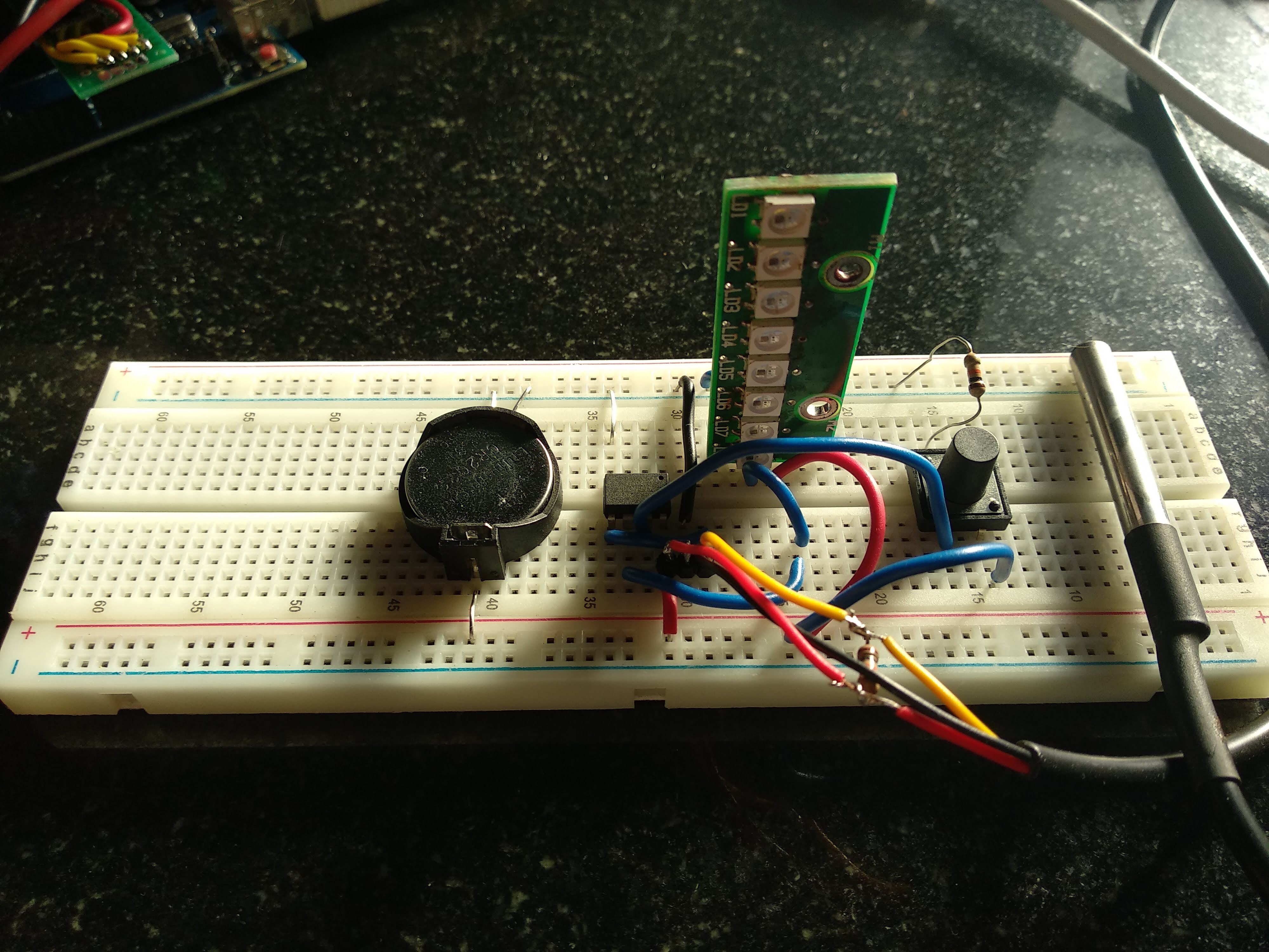
Some of these were easy to meet( based on experience), but some were big question marks. Nevertheless, I started to order parts and put together a basic working circuit i could test and refine my code. 
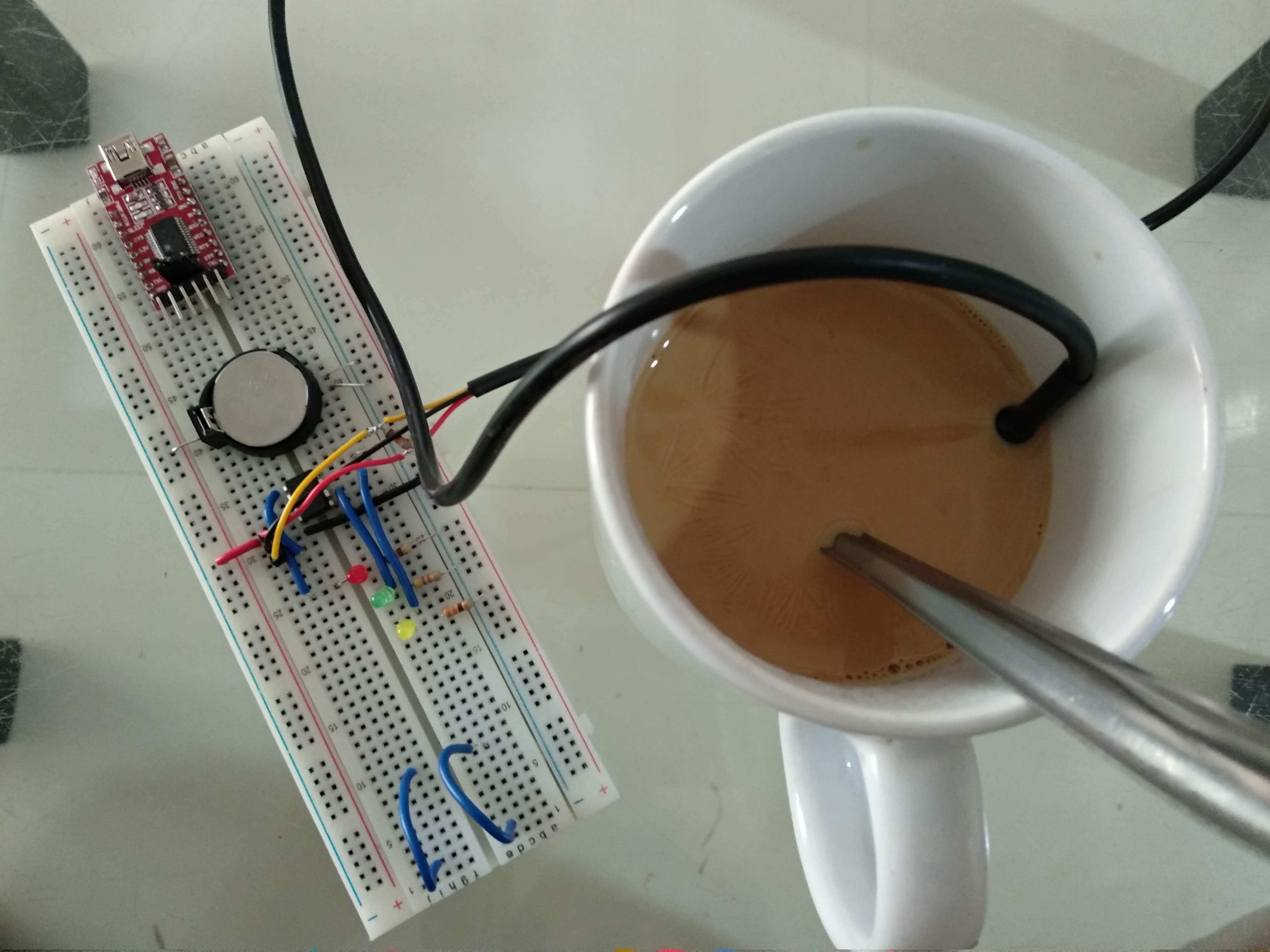
I initially thought of not putting a Li Ion Battery because of export restrictions and certifications I would require to go through. I planned my design around a CR2032 battery. 

The battery ran for quite a few days before it drained and was rejected as the product size was starting to get cumbersome. 

My initial prototype was also with a Red, Yellow and Green discrete LED tied to the I/O pins of the Attiny85. 

I got better and better information about the behavior of the system, which brought confidence to go ahead and attempt the Low Power code for the Attiny85. 

  • 1 × ATTiny85 Microprocessors, Microcontrollers, DSPs / ARM, RISC-Based Microcontrollers
  • 2 × SK6812 4020 Side LED RGB LED compatible with WS2812B, but illuminates from the side
  • 1 × Ds18b20 Sensors / Temperature, Thermal
  • 1 × SMD Switch
  • 1 × LTC4054 Power Management ICs / Power Supply Support

View all 6 components

  • First Test Video

    DailyDIY05/25/2019 at 05:15 2 comments

    Here is a time lapse of the prototype in action 

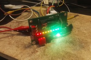
    Finally, the first #test video for the #hotornot project. I grabbed a cup of tea and dipped the #sensor in the tea. In the #timelapse you will see the #LEDs blink in red(>60C) , yellow(between 60c and 55C) and green(below 55C). I got impatient and drank the #tea much after the yellow blinks. I removed the sensor, the temperature dropped, and the LED started to blink Green. Once the temperature went below 40C, the whole system automatically was shut down, waiting for the next press of a #button

    #coffeelovers #tealovers #tech#technology #diy #doityourself

  • Designing the PCB

    DailyDIY05/15/2019 at 13:59 0 comments

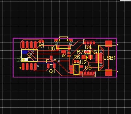
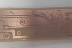
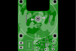
    It took me a while to design a PCB in EasyEDA. 

    Firstly there were two leaps of faith I took 

    1) I did not test the SK6812 LED because I had none. I read up on the LED documentation and it was identical to the WS2812B LED. 

    2) The LTC4054 Li Ion charger chip, I had no experience designing with it. 

    I read up on a lot of design notes for both the devices and figured out what was that I needed. 

    For the SK6812 LED, I figured out that soldering it by hand will be a pain. But I couldn't find an alternative to it. Easy EDA had the component designed, and I used it. I also ended up verifying the pad layout of the design against the LED mechanical drawings and confirmed it was within spec. 

    The LTC4054 was a simple enough chip to work with. I set the charging current of the Li Ion Battery to 200mA, as my battery was 300mA, which makes the charging current less than 1C, and is overall good for the battery and the charger. 

    I purchased a battery and sized my PCB to it. The PCB dimensions are 30mm x 15mm,  and all the components are on the top side of the PCB. 

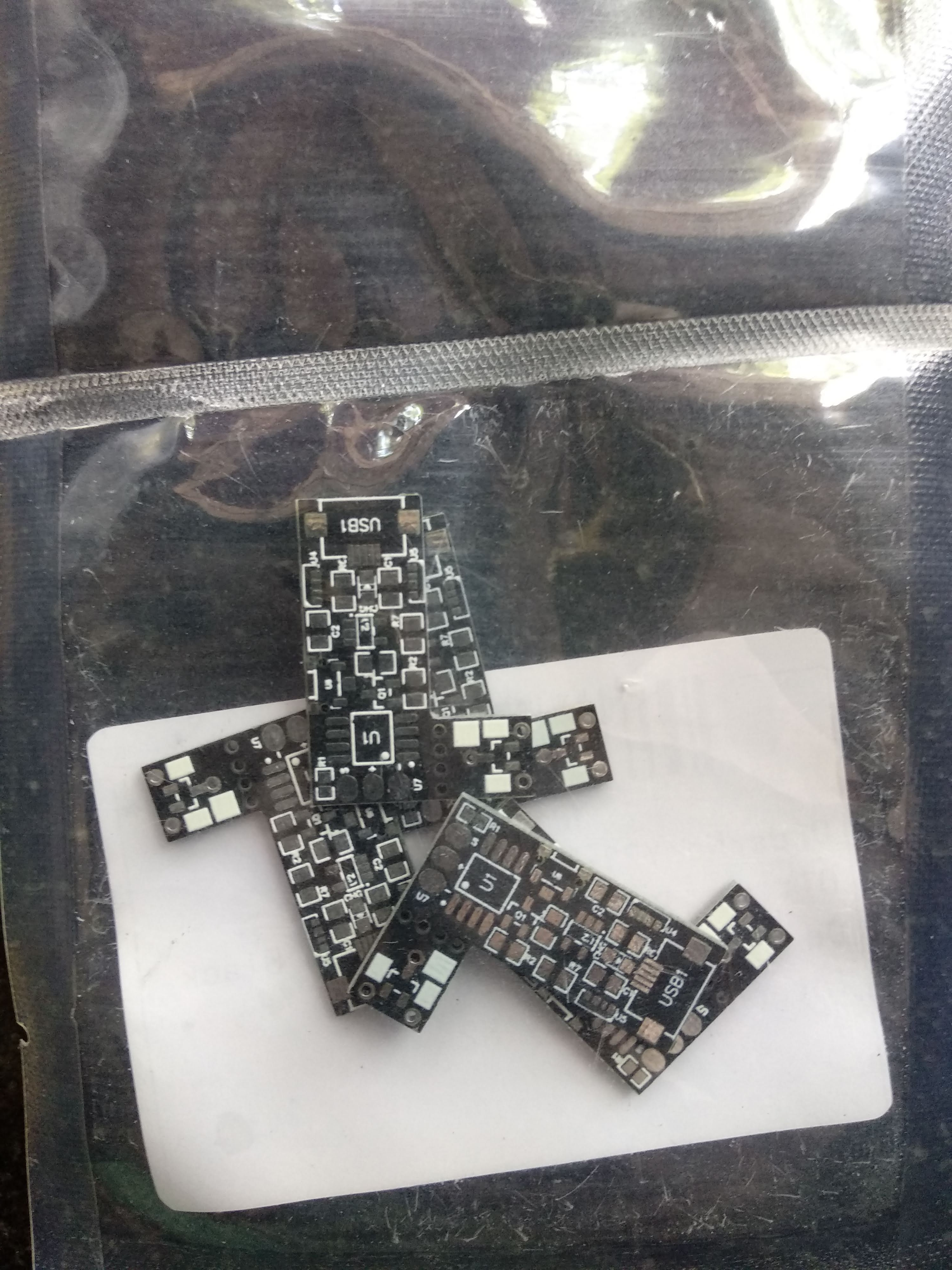
    I put in a order at JLCPCB in last week of April, and the PCB's came by the first week of May. 

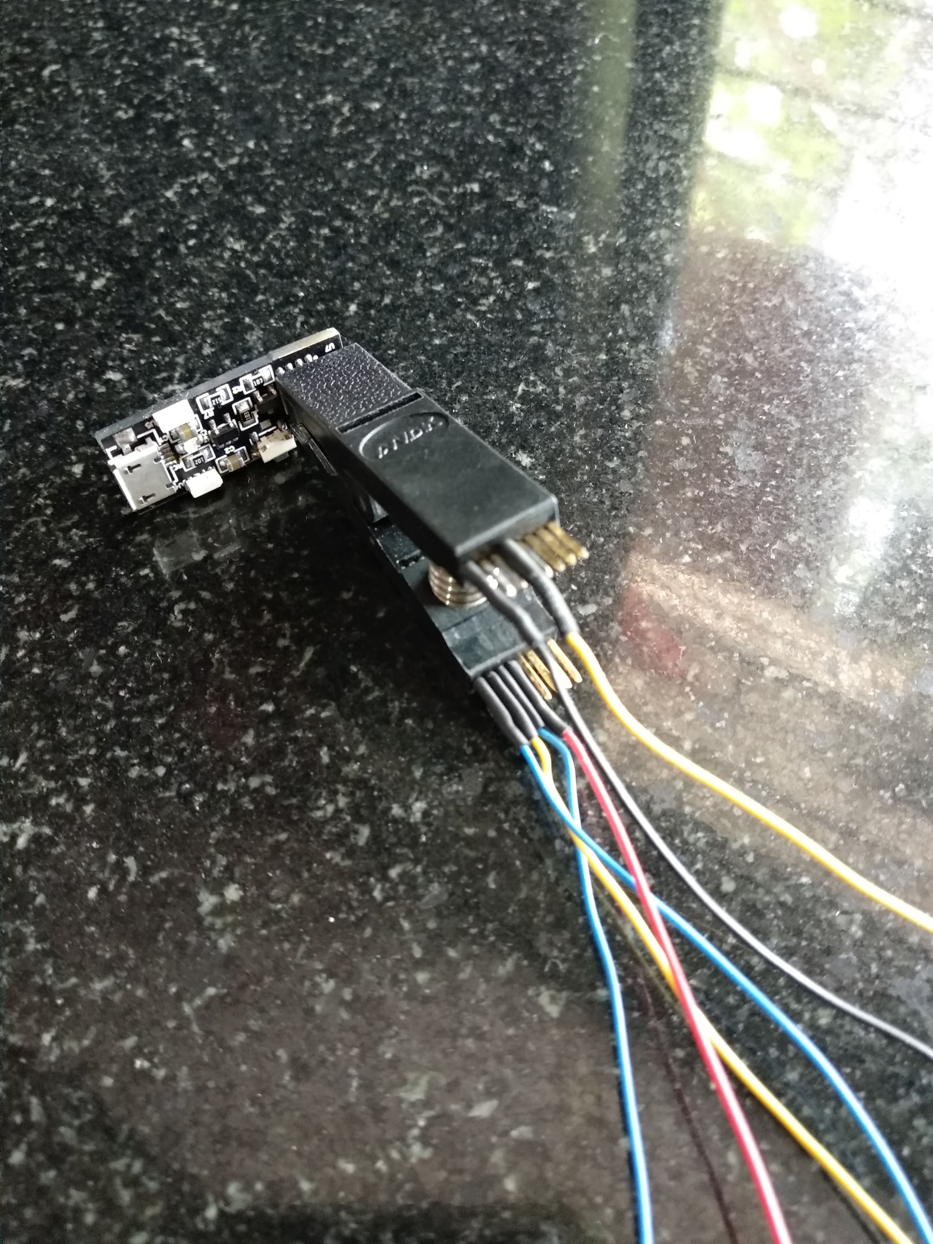
    A friend who has a steady hand and repairs phone for a living helped me solder all the parts for the PCB. The most difficult was the SK6812 LED. Everything was soldered exceptionally well, and I have done basic tests on the LED's and the ATtiny as well. 

    In image below, the SK6812 LED's are the two white rectangles on the edge of the board, on the right of the USB Micro connector.  The LTC4054 is the small 5 legged chip in the middle of the board. The white rectangle on the bottom edge of the board( right of the LTC4054) is the reset button. The ATtiny85 is the 8 legged SOIC chip. the three pads at the very extreme right are to connect the DS18b20 temperature sensor.

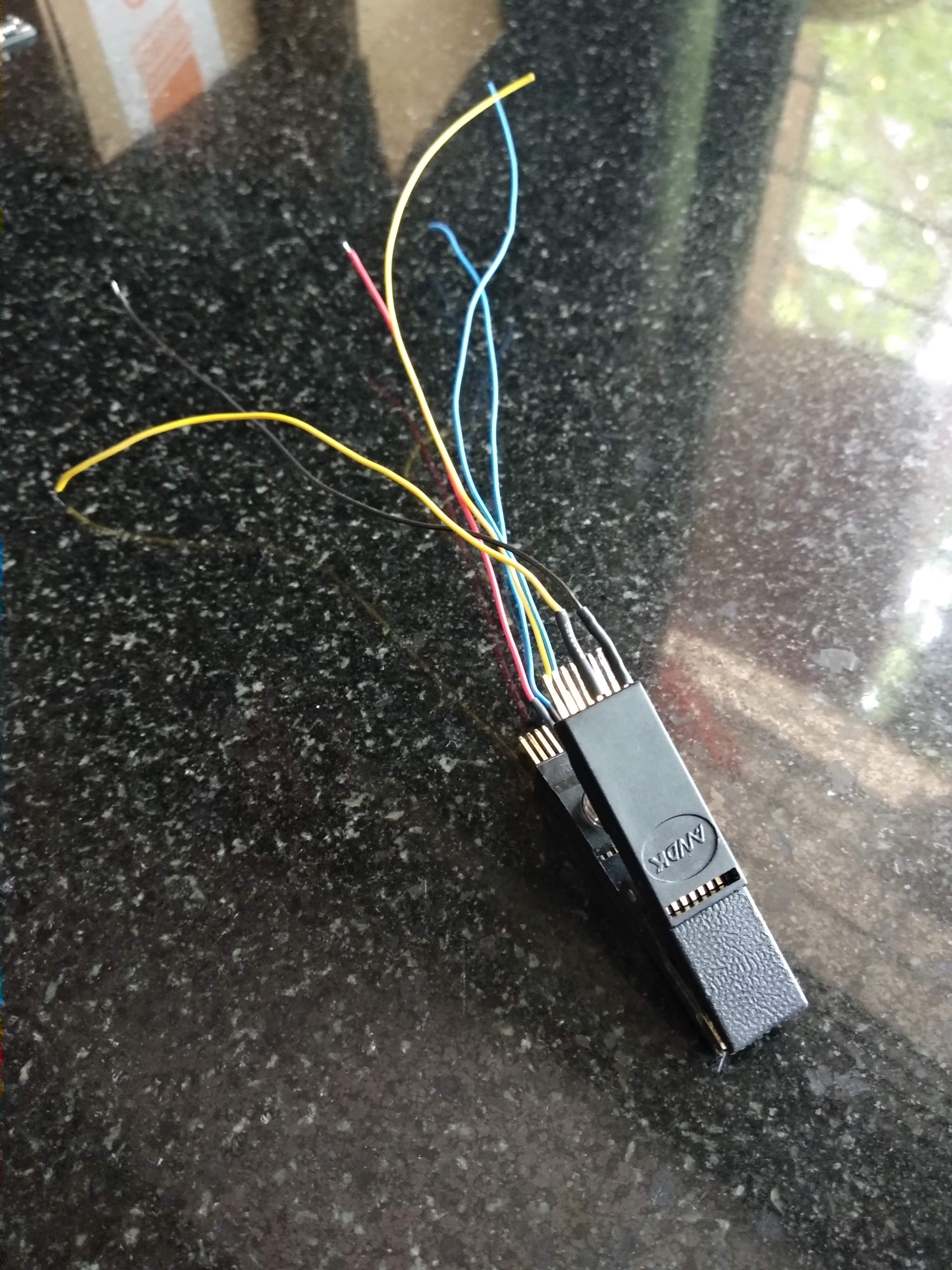
    I have a SOIC clip adapter which I am using to program the ATtiny85 as shown below. 

    I keep updating my project progress on Instagram, with videos as well. 

  • Shift to WS2812B and Low Power MOSFET

    DailyDIY05/15/2019 at 11:05 0 comments

    I shifted my LED from discrete to RGB WS2812 ones, because I realised i may need more I/0 Pins for other uses. 

    I also figured out that the discrete LED's cannot provide for a good range of illumination i was hoping for, without resorting to PWM. 

    I had experience using the WS2812B LED's and I liked them a lot, but my only worry was their standby current draw when they are not lit. Each LED can draw about 1mA from the Battery when it is not on, thereby wasting power when it serves no purpose. 

    Even when the Attiny85 was sleeping, the current draw of the DS18b20 and the WS2812LED strip of 8 LED's was about 40mA, which was a big problem area. 

    There was an idea. I switched on the LED and the Ds18b20 sensor using a Logic Level mosfet. 

    I set my eyes on the AO3416 Mosfet which has a low Rds(on) of 22mohm when the Vgs was 1.8v. This mosfet was a perfect choice to put in my circuit and try. 

    I managed to lower the standby power need from 40mA to under 1uA by using the Mosfet. I did gain a little on time, because once the power to the LED was cut off, it has to be reinitialized and that took some time to happen. 

    The tactile button in the above image is used to wake up the Attiny85 from deep sleep and start measuring the temperature. 

    Overall, I was happy with the whole circuit and decided it was time to design a PCB for the whole circuit. 

View all 3 project logs

Enjoy this project?

Share

Discussions

Chaz wrote 06/24/2019 at 19:13 point

Glad to see this being worked on. I had a similar adventure in 2014 trying to fit it all inside the size of a pencil. ended up ditching all the electronics in favor of a bimetal switch to turn an LED on when it was above 145F. 

A good battery suggestion is a CR435. used in fishing lures. very skinny.

If anyone cares to see the prototype: https://photos.app.goo.gl/Vop9jK6k81FQp7cH9

  Are you sure? yes | no

DailyDIY wrote 07/09/2019 at 14:45 point

The battery is wicked! what kind of PCB connector is used for this battery? How does the end user replace it? 

  Are you sure? yes | no

marble wrote 06/13/2019 at 14:07 point

One idea that came to mind while watching the Mentor Session video is to make something like these mugs that change their printed on picture when hot water is pored into it.

Maybe something like a thermometer that's made of sections of thermochromic ink that change their appearance at different temperatures.

  Are you sure? yes | no

Similar Projects

Does this project spark your interest?

Become a member to follow this project and never miss any updates