Rupin Chheda
-
First Test Video
05/25/2019 at 05:15 • 2 commentsHere is a time lapse of the prototype in action
Finally, the first #test video for the #hotornot project. I grabbed a cup of tea and dipped the #sensor in the tea. In the #timelapse you will see the #LEDs blink in red(>60C) , yellow(between 60c and 55C) and green(below 55C). I got impatient and drank the #tea much after the yellow blinks. I removed the sensor, the temperature dropped, and the LED started to blink Green. Once the temperature went below 40C, the whole system automatically was shut down, waiting for the next press of a #button
#coffeelovers #tealovers #tech#technology #diy #doityourself
-
Designing the PCB
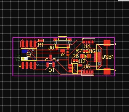
05/15/2019 at 13:59 • 0 commentsIt took me a while to design a PCB in EasyEDA.
![]()
Firstly there were two leaps of faith I took
1) I did not test the SK6812 LED because I had none. I read up on the LED documentation and it was identical to the WS2812B LED.
2) The LTC4054 Li Ion charger chip, I had no experience designing with it.
I read up on a lot of design notes for both the devices and figured out what was that I needed.
For the SK6812 LED, I figured out that soldering it by hand will be a pain. But I couldn't find an alternative to it. Easy EDA had the component designed, and I used it. I also ended up verifying the pad layout of the design against the LED mechanical drawings and confirmed it was within spec.
The LTC4054 was a simple enough chip to work with. I set the charging current of the Li Ion Battery to 200mA, as my battery was 300mA, which makes the charging current less than 1C, and is overall good for the battery and the charger.
I purchased a battery and sized my PCB to it. The PCB dimensions are 30mm x 15mm, and all the components are on the top side of the PCB.
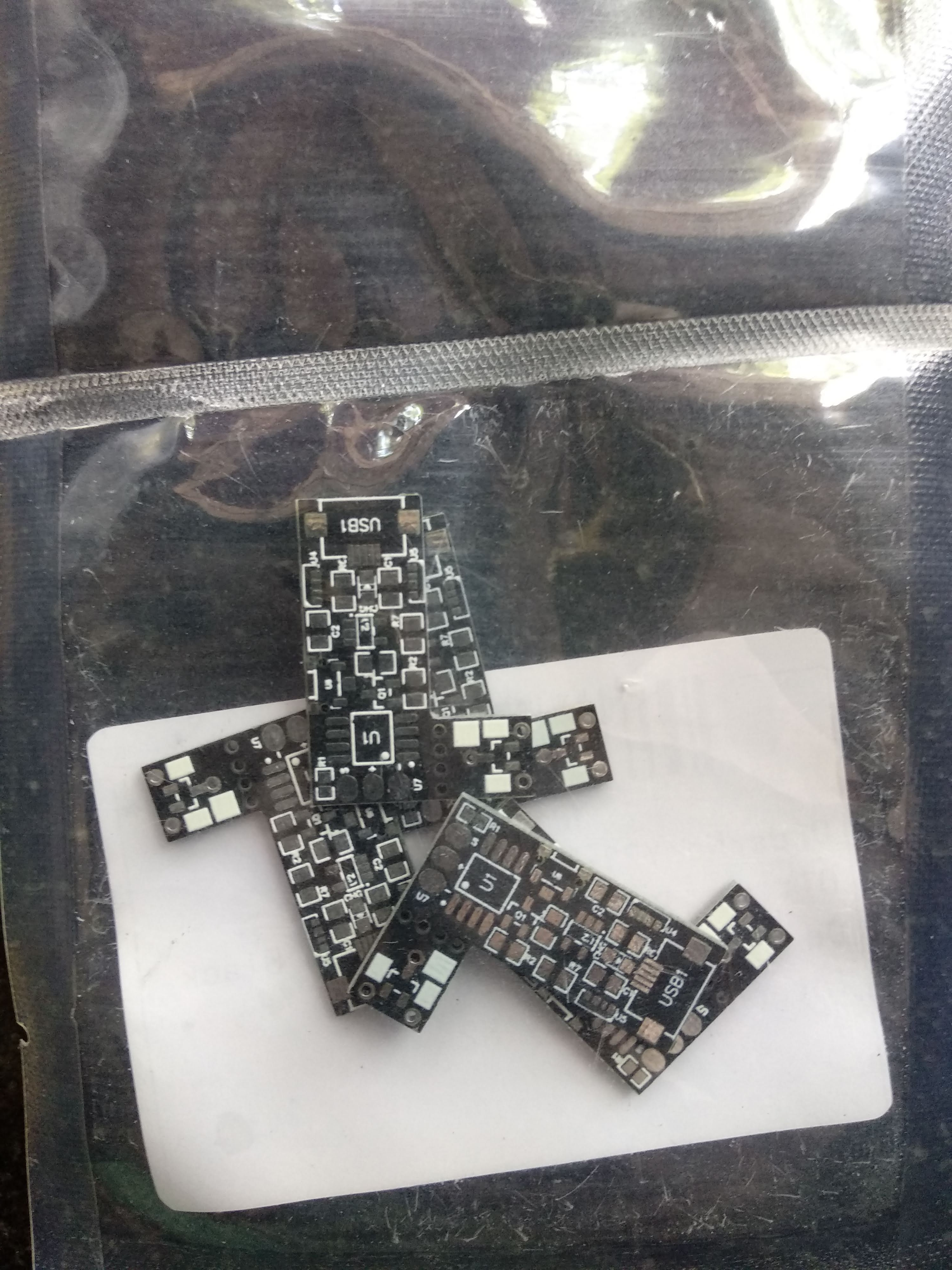
I put in a order at JLCPCB in last week of April, and the PCB's came by the first week of May.
![]()
A friend who has a steady hand and repairs phone for a living helped me solder all the parts for the PCB. The most difficult was the SK6812 LED. Everything was soldered exceptionally well, and I have done basic tests on the LED's and the ATtiny as well.
In image below, the SK6812 LED's are the two white rectangles on the edge of the board, on the right of the USB Micro connector. The LTC4054 is the small 5 legged chip in the middle of the board. The white rectangle on the bottom edge of the board( right of the LTC4054) is the reset button. The ATtiny85 is the 8 legged SOIC chip. the three pads at the very extreme right are to connect the DS18b20 temperature sensor.
![]()
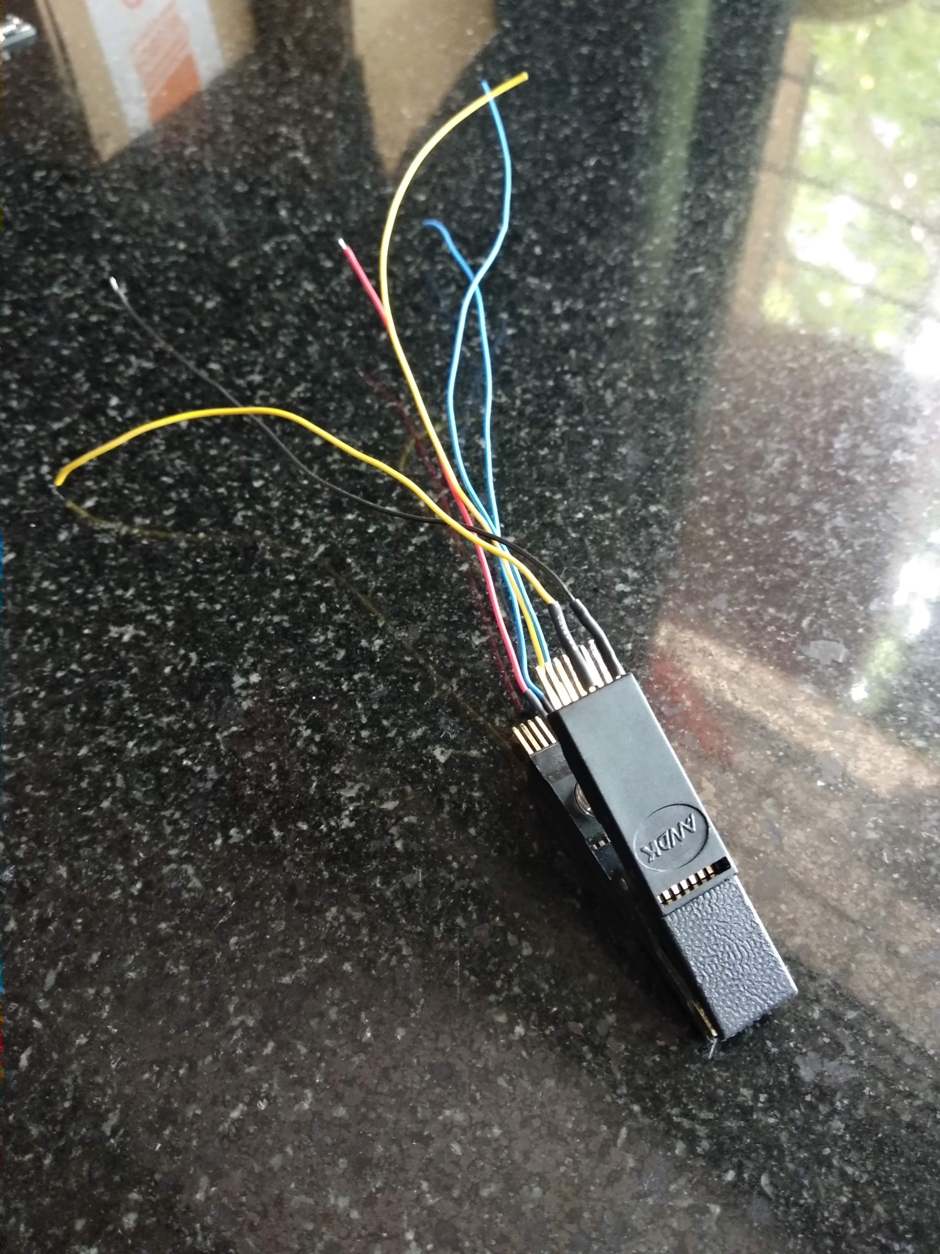
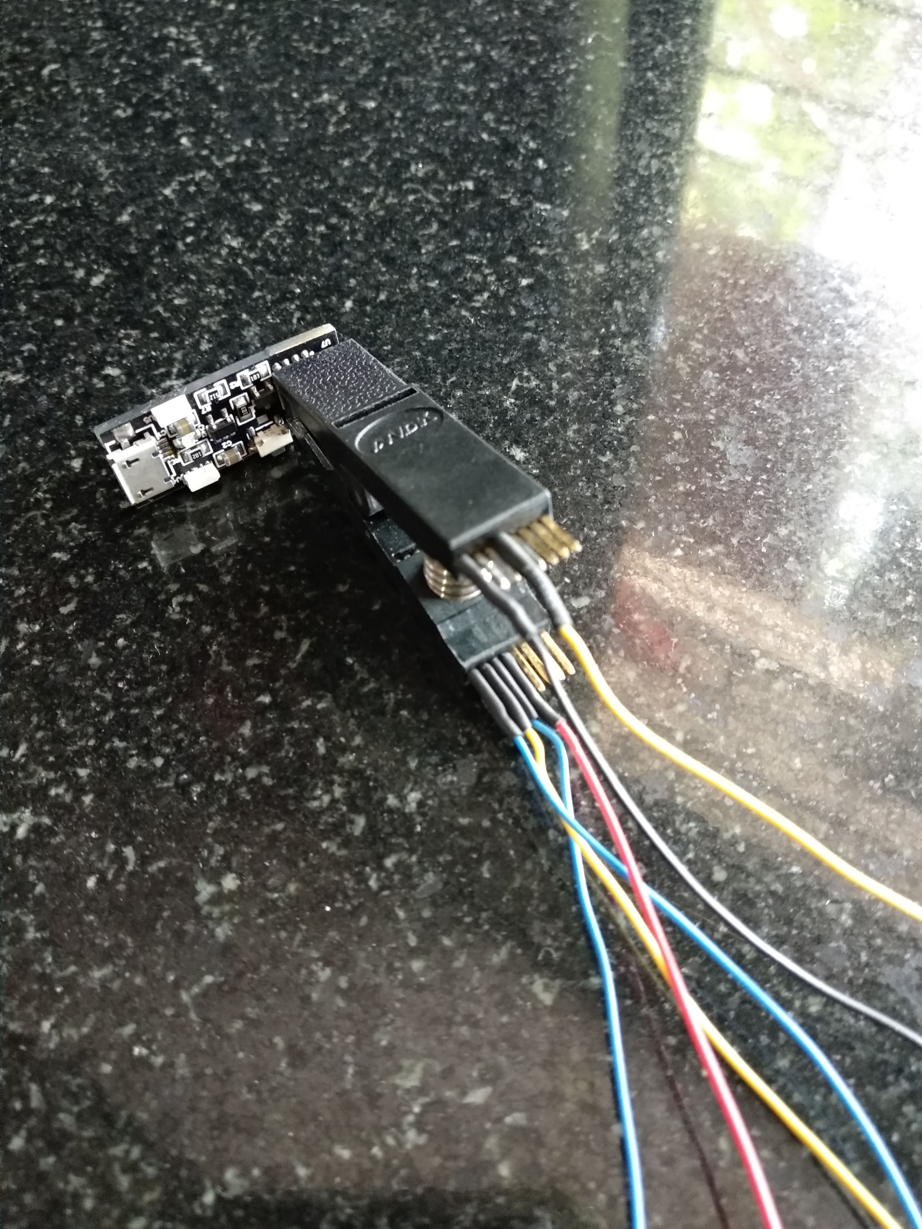
I have a SOIC clip adapter which I am using to program the ATtiny85 as shown below.
![]()
![]()
I keep updating my project progress on Instagram, with videos as well.
-
Shift to WS2812B and Low Power MOSFET
05/15/2019 at 11:05 • 0 commentsI shifted my LED from discrete to RGB WS2812 ones, because I realised i may need more I/0 Pins for other uses.
I also figured out that the discrete LED's cannot provide for a good range of illumination i was hoping for, without resorting to PWM.
I had experience using the WS2812B LED's and I liked them a lot, but my only worry was their standby current draw when they are not lit. Each LED can draw about 1mA from the Battery when it is not on, thereby wasting power when it serves no purpose.
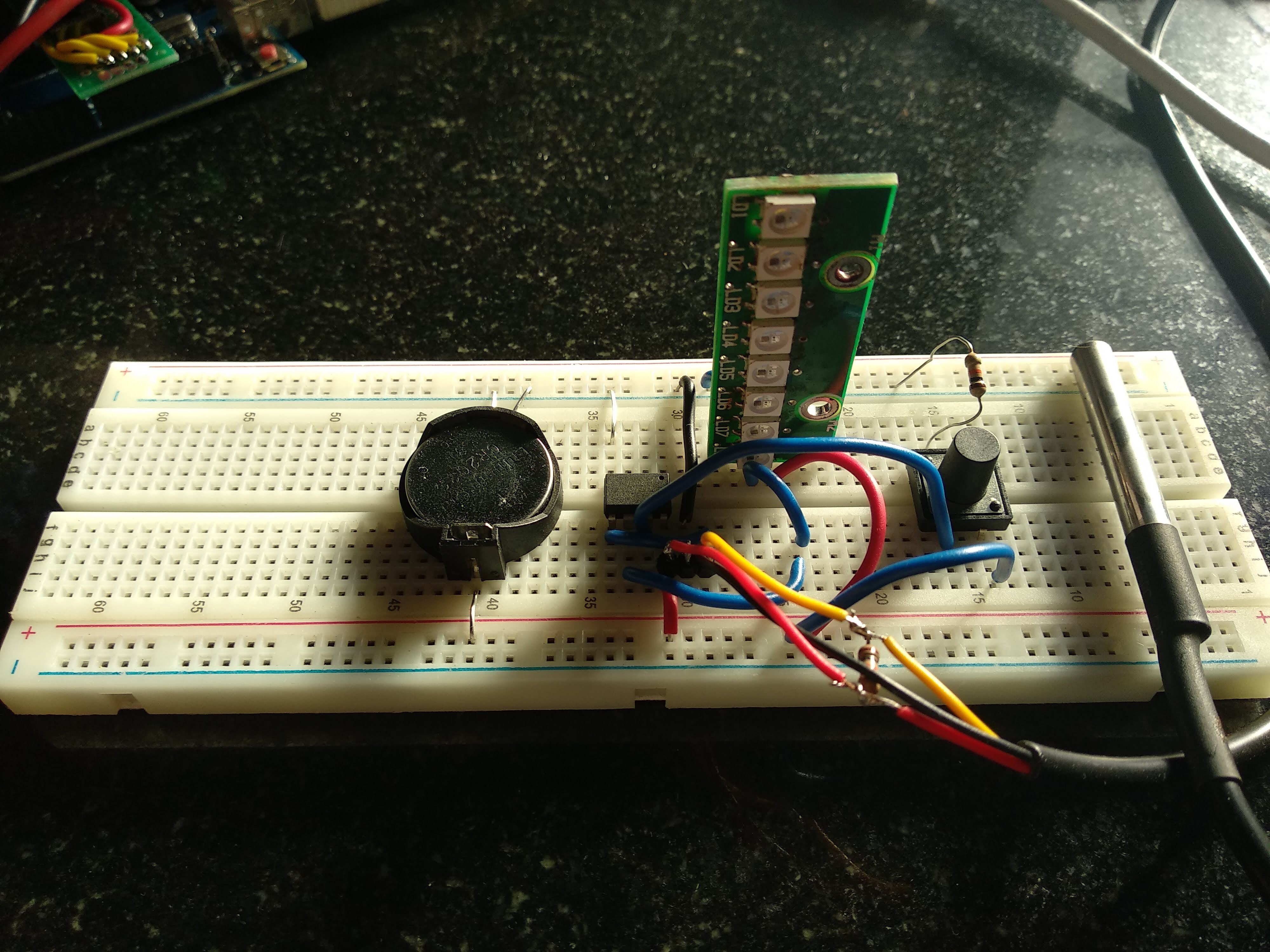
![]()
Even when the Attiny85 was sleeping, the current draw of the DS18b20 and the WS2812LED strip of 8 LED's was about 40mA, which was a big problem area.
There was an idea. I switched on the LED and the Ds18b20 sensor using a Logic Level mosfet.
I set my eyes on the AO3416 Mosfet which has a low Rds(on) of 22mohm when the Vgs was 1.8v. This mosfet was a perfect choice to put in my circuit and try.
I managed to lower the standby power need from 40mA to under 1uA by using the Mosfet. I did gain a little on time, because once the power to the LED was cut off, it has to be reinitialized and that took some time to happen.
The tactile button in the above image is used to wake up the Attiny85 from deep sleep and start measuring the temperature.
Overall, I was happy with the whole circuit and decided it was time to design a PCB for the whole circuit.
HotOrNot Coffee Stirrer
A smart Beverage Stirrer to notify when it is safe to drink without getting singed.