 FrazzledBadger
So I've been beavering away on designing the first PCB for this project, a MEMs microphone and preamplifier board, this pcb will hopefully fit into each headphone, so I've designed it to be reasonably small. I'm sure I could of gone smaller with 0402 components and a smaller OpAmp, but I didnt feel the need. As it is, the PCB measures 17mm x 22mm.
I've used the same opamp design as for my test board, it seemed to be a reasonable circuit, and has scope to play with the gains by changing out components. The only difference is I've added the MEMs microphone, a LDO Regulator and a 3 pin header.
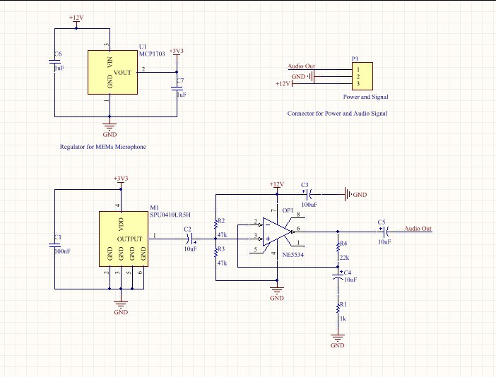
Interestingly the MEMs datasheet specifies no Catagory 2 Dielectrics in the capacitors, this wasn't a term I'd heard before, but after a quick Googlify, I found out it meant I couldn't use X7R or X5R dielectrics, so C1 is a C0G and C2 is a Tantalum Electrolytic, as I could only find Class 2s in the 10uF size. The footprint is 1206 though, so this gives me plenty of scope to chop and change.
After an afternoon of laying out, I ended up with this:
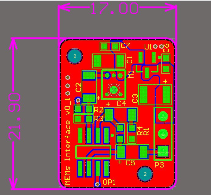
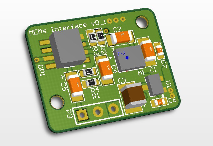
I'm pleased with it, its a reasonably compact design without going crazy, M1 is the MEMs microphone, the aperture is underneath, so I had to design in a large via in the board. Should be interesting to solder.....
I'm going to design the main board next and then send both off to Seeed Studios, to get the advantage on postage.
Discussions
Become a Hackaday.io Member
Create an account to leave a comment. Already have an account? Log In.
OK. It's working now. There was a loose contact.
Thanks,
H
Are you sure? yes | no
Cool. Thanks and good luck!
Are you sure? yes | no
Hi, to be honest, its still on my shelf waiting to be built! I'll throw it together this week and give it a test.
Thanks
Are you sure? yes | no
Hi!
Die you ever get the microphone PCB to work?
We're having issues concerning the microphone. It does not output anything at all.
Greetings,
H
Are you sure? yes | no