FrazzledBadger
-
Soggy Saturday Syndrome
07/19/2014 at 11:53 • 0 commentsWell, rain has stopped me from working on my camping kitchen project today, so I'll do another DogEars update.
I've chosen my FPGA, I've gone for a Spartan 6 LX9 chip, it seems to be able to fit all the FFT goodness I need with plenty of space left over for any extra magic I need. Big advantages are its a 144 pin TQFP, which if loverly compared to a BGA, so will be simpler to design. Plus its only £15 from Farnell, which isn't too bad for a chip of this calibre.
I've initially decided to use SPI Flash to store the configuration files, but am planning on having it switchable, so the microprocessor can also program the FPGA.
I'm currently working through my main pcb design, I want to basically make it a useful generic pcb, that can be put into a breadboard. I'm trying not to go too mad with it, feature creep is a swine...
So far I'm planning on including:
2 ADCs in and 2 DACs out for the audio conversion, these could be used in the future for any signal conversion, eg sensors etc. I've chosen the Touchstone Semiconductor TS7003 for the ADCs as they are 12bit, 300KSPS and only cost £1.46 each. For the DACs, I went a Wolfson WM8759 Stereo Headphone Amplifier, these are 24bit, 192KSPS and only cost £1.07 each. The Wolfson takes a variety of digital audio signals, for example I2S or AES. The FPGA will have to have this interface coded into it.
Blutooth Interface, which will basically be a header and components for one of the cheap blutooth boards from eBay.
Ultrasound Transmitter interface
A Microprocessor with SD card interface because it may be useful ,plus I'd like to play around with updating the alll the firmware from SD card at some point. This is something I keep meaning to play around with as it will be really useful for other applications.
IO Ports, these will be breadboard pin compatible, I will try to externalise as many pins as possible, you can never have too much IO!
A Highspeed connector for daughterboards. I was getting excited about including things like ethernet, usb, maybe some sort of LCD interface, but this makes the project way more complex than it needs to be, so I decided to put a highspeed connector on the PCB, to allow me to design the other toys on daughteboards at a later date, subject to whatever requirements I need. This is the beauty with having access to such cheap boards from places like Seeed or OshPark, a few years ago these designs would have been too expensive for me to have had made.
In other news, I've stepped into the scary world of GitHub, I'm planning on totally opening up the project, and making schematics, code and gerbers accessible. Check it out, the link is underneath my pictures.
I've also had a quick look at Android programming, with the view to creating an app for this, not sure how complex this will be, its not something I've tried before, but as my brother says, "How hard can it be?".......
If it proves him wrong, I may do a prototype just using python scripting on my phone initially.
-
Quick Update!
07/15/2014 at 05:47 • 1 commentJust a quick update, I've been thinking about how to do the main FFT transformations, I need to do 2 FFT and 2 Inverse FFT calculations at the same time. To me, this immediately shouts FPGA, so I am currently researching the best chip to use. I'm thinking I could also produce a small tutorial on how to use FPGAs, including designing them into a circuit, board payout and soldering the little swine down.. BGAs.. urgh..
I'm also thinking it would be nifty to produce a board with FPGA and associated gubbins on it that has pinouts so it can be breadboarded or have headers attached. This would be great for future projects.
So far I think the pcb should contain:
FPGA(obviously..)
Power Supplies, it would be great to run it off a single 5v supply
a couple of ADC and DAC convertors
Program Flash
RAM
There is another project entered into the Hackaday Prize which is similar to DogEars, so to add a unique twist, I want to add a couple of ultrasonic transmitters, and investigate whether humans can be trained to use echolocation to navigate a dark environment. This would be a fascinating experiment and would have positive benefits, for example for blind/partially sighted people.
I want to investigate human ears, specifically the angle of hearing created by the shape of the ear, this could then be replicated with a 3d printed doodad to give the most accurate replication. This would then allow the wearer to sense the direction of the sounds.
-
MEMs Microphone PCB Design
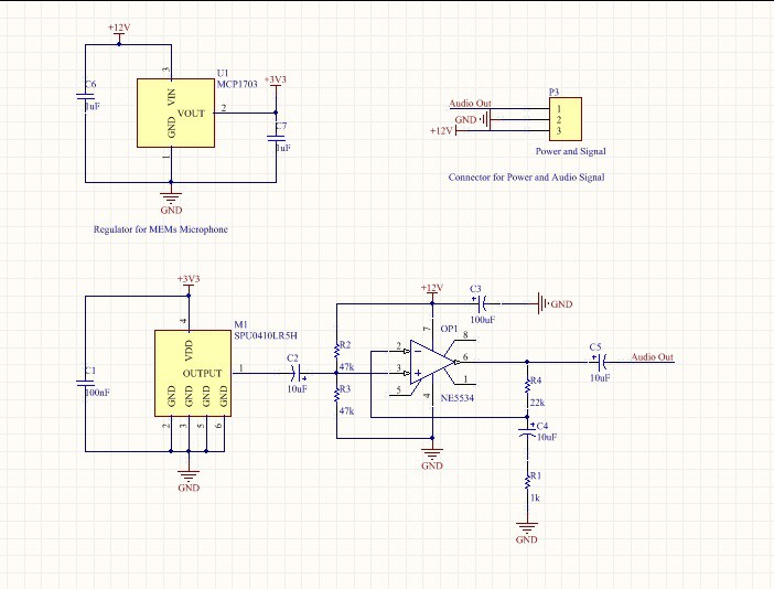
07/01/2014 at 19:29 • 4 commentsSo I've been beavering away on designing the first PCB for this project, a MEMs microphone and preamplifier board, this pcb will hopefully fit into each headphone, so I've designed it to be reasonably small. I'm sure I could of gone smaller with 0402 components and a smaller OpAmp, but I didnt feel the need. As it is, the PCB measures 17mm x 22mm.
I've used the same opamp design as for my test board, it seemed to be a reasonable circuit, and has scope to play with the gains by changing out components. The only difference is I've added the MEMs microphone, a LDO Regulator and a 3 pin header.
![]()
Interestingly the MEMs datasheet specifies no Catagory 2 Dielectrics in the capacitors, this wasn't a term I'd heard before, but after a quick Googlify, I found out it meant I couldn't use X7R or X5R dielectrics, so C1 is a C0G and C2 is a Tantalum Electrolytic, as I could only find Class 2s in the 10uF size. The footprint is 1206 though, so this gives me plenty of scope to chop and change.
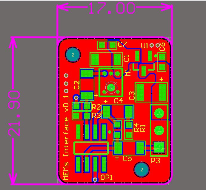
After an afternoon of laying out, I ended up with this:
![]()
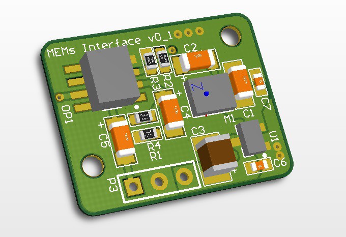
I'm pleased with it, its a reasonably compact design without going crazy, M1 is the MEMs microphone, the aperture is underneath, so I had to design in a large via in the board. Should be interesting to solder.....
![]()
I'm going to design the main board next and then send both off to Seeed Studios, to get the advantage on postage.
-
Electret and Amplifier Test Design
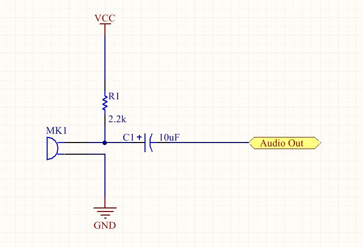
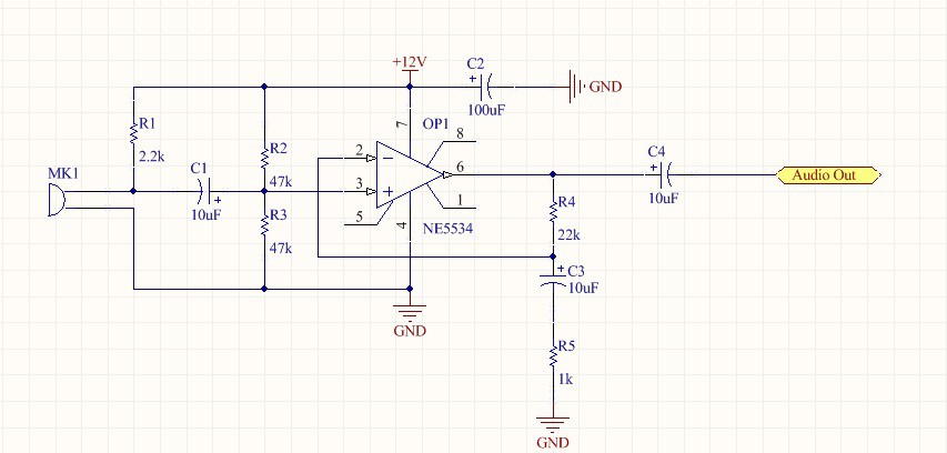
06/28/2014 at 21:57 • 0 commentsThe first step of this project is to build a Electret Element test board. I've chosen the Panasonic WM-61A element for this. A basic circuit to power it is thus:
![]()
Here, the resistor is to restrict current flow and seperate the Vcc line from the audio signal, and the capacitor is used to AC couple the signal.
This audio is the fed into an opamp, I'll use NE5534 for this. Its only for test purposes, so doesnt have to be too fancy, just a general low noise one will be fine. The final schematic of the element and preamplifier look like this:
![]()
-
Microphone Selection
06/28/2014 at 19:42 • 0 commentsSo theres essentially 4 types of microphones, piezo transducers, electret, electrostatic and MEMs.
Piezo Transducers.
These are generally flat discs that uses a piezoelectric effect, essentially when it is distorted by sound waves, it generates a small amount of electricity. The disadvantage with these is they are generally only used for a narrow frequency range, eg around 40kHz.
Electret Elements.
These are the generic microphone element, used in everything from camera microphones to toys. Cheap and readily available, they are rated for around 20 to 20kHz, but some do respond well to up to 100KHz. A popular one for bat detection is the Panasonic WM-61A,
http://www.panasonic.com/industrial/components/pdf/em06_wm61_a_b_dne.pdf.
The only problem with this is there is no hard data on the response above 20kHz.
Electrostatic Elements.
These are essentially capacitors where the sound vibrations cause a change in the distance between the plates. They have a good range, up to 200kHz, but need a high voltage, around 200V to use. This isn't something I want to strap to my head....
MEMs Elements.
These are the new kids, small surface mount packages with the element etched directly onto the silicon wafer. There are only a few that have their high frequency response documented, one such example is SPU0410LR5H from Knowles.
http://www.knowles.com/eng/Products/Sensors/Ultrasonic
This has the the response described up to 80kHz, and is also a very small package, being only around 3mm2, and only 1.1mm high.
Conclusions.
Well, all things considered I think I will take a 2 pronged approach to this. I will design my PCBs to use the Knowles MEMs elements, but for testing and development purposes I will buy a couple of Panasonic electret elements, this means I can develop the system whilst the PCBs are being made.
-
Initial Research
06/28/2014 at 18:05 • 0 commentsOk, this project will be split into multiple parts (obviously..). I envision these being:
Microphone selection.
Analogue audio amplifer and ADC design.
DAC design and headphone amplifier.
Processor/FPGA Selection.
Power Supply selection/design.
Bluetooth Integration.
Smartphone programming.
DSP research and programming.
Prototype and test.
Assembly.
DogEars
This is a project to create superhuman hearing for everyone, finally we too can get annoyed by parking sensors and listen to bats!