WestfW
-
Uno-style board Blinking.
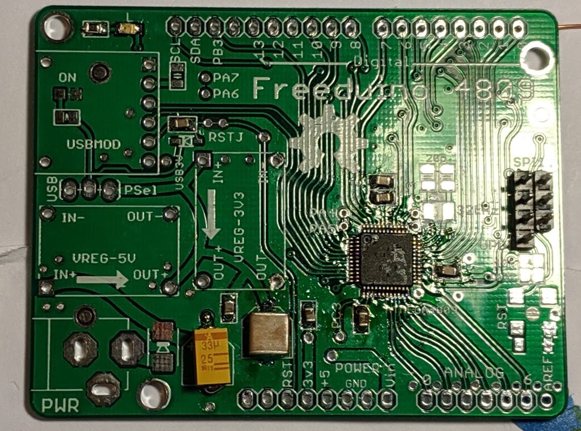
08/06/2019 at 09:14 • 2 commentsA "Freeduino 4809", the board with the Uno pinout, has now also been assembled, runs a Blinky and Hello World program (on an entirely different pin/USART than the DIP version.)
Pay no attention to the capacitors that don't match the PCB footprints. They fit, mostly, and are what I have in the junk box!
![]()
The TX and RX pins on this board are also swapped from how they need to be. :-( I'm going to start putting a set of crossover pads on any PCB where they'll fit!
-
DIP Boards have swapped Rx/Tx
07/31/2019 at 05:52 • 4 commentsSigh. The DIP boards have the RX and TX pins swapped at the ATmega side. A crossover works ("Hello World!" !!), and it's less relevant if you're not using particular USB/Serial module I'm using, but it's annoying. I could swear I had checked that carefully :-(
void uart_init() { VPORTA.DIR |= 1<<4; // set TX pin to output VPORTA.OUT |= 1<<4; // and "1" as per datasheet PORTMUX.USARTROUTEA = 1; // alternate pinout to use PA4/5 USART0.BAUD = (64ULL * F_CPU)/(16UL*BAUDRATE); USART0.DBGCTRL = 1; // run during debug USART0.CTRLC = (USART_CHSIZE_gm & USART_CHSIZE_8BIT_gc); // Async, Parity Disabled, 1 StopBit USART0.CTRLA = 0; // Interrupts: all off USART0.CTRLB = USART_RXEN_bm | USART_TXEN_bm; } -
Hmmph. Board is short.
07/05/2019 at 08:09 • 0 commentsMy intent was to reject the "Italian Style" Arduino board shape and use a simple rectangle the same size as my previous "Freeeduino" board (as sold by NKCElectronics.) But on comparison, while I removed the funny shape, I forgot to move the left edge of the board, and it's about 6mm shorter than the Freeduino. That's not a big deal, but I'm annoyed with myself, particularly since it would have made it easier to fit those power supply modules...
-
Boards have arrived
06/23/2019 at 05:14 • 1 commentBoards have arrived. I made some errors on the bottom silkscreen, and there are some other things I don't like WRT which vias I had tented, but they look pretty good. (Even the slots of the power connector look rightl the advantage of starting with someone else's part definition, or perhaps clever engineers at PCBWay...)
Now to try to muster the courage to solder those 0.5mm-pitch TQFPs :-(
(The bottom boards are 4809 DIP "completers"...)
![]()
-
PCBs are being made
06/11/2019 at 09:33 • 0 commentsSent out for PCB fab (at PCBWAY.com)
-
Silkscreen?
05/30/2019 at 08:05 • 0 comments![]()
-
Getting closer
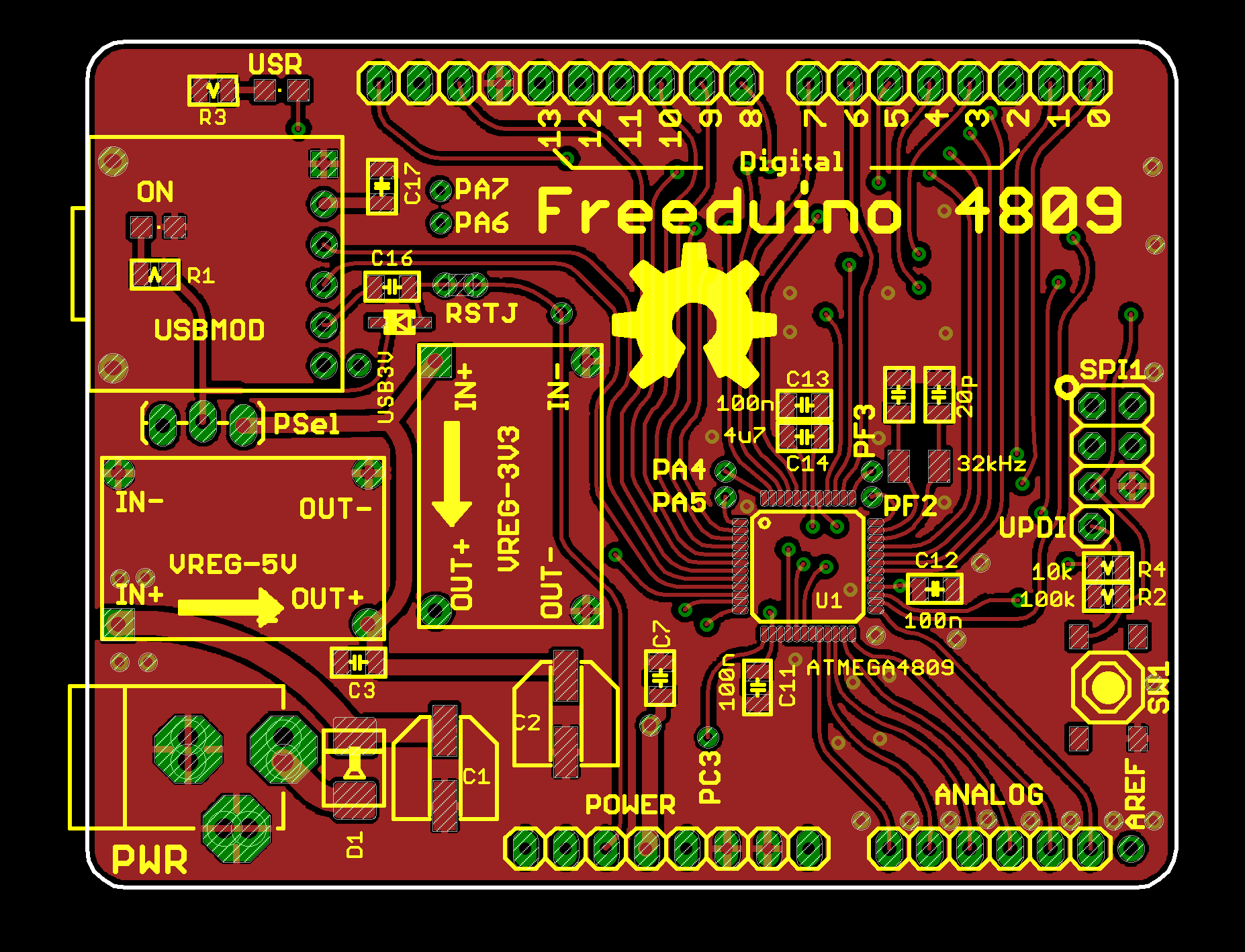
05/24/2019 at 07:12 • 0 commentsI did it - Got rid of Aref. and connected PB3 to that connector instead. Brought out the Aref signal next to the analog pins...
I've inflicted the "WestfW Style" on the layout :-)
Next step, silkscreens...
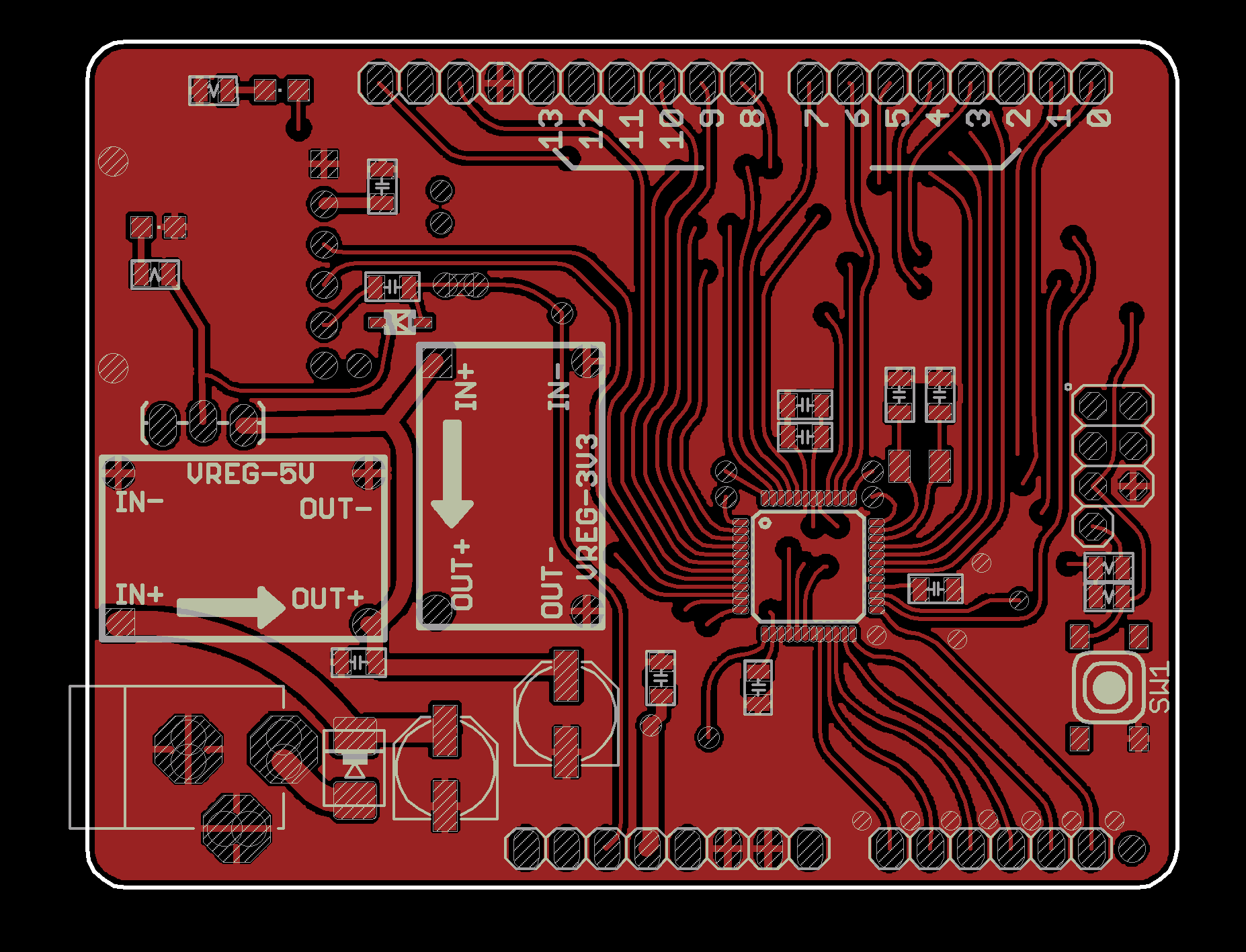
![]()
![]()
(The USB module isn't really on the bottom. It's on the top, but upside down. I guess I should make that a package option.(
-
Fiddling.
05/23/2019 at 01:47 • 0 commentsThe board is designed to be partially populated. The USB module has power and data LEDs, so the pwr LED is sort-of "underneath" that, if you're not using USB. The 3.3V regulator could be omitted, with the 3.3v pad connected to the USB module (if you only need as much current as the ch340e can provide (which I assume is even less than the 50mA you can get from an FTDI.)
Thinking of moving or removing Aref; it's on the wrong side of the board (physically and electrically), I don't think anyone ever uses it, and the 4809 has more Aref options internally.
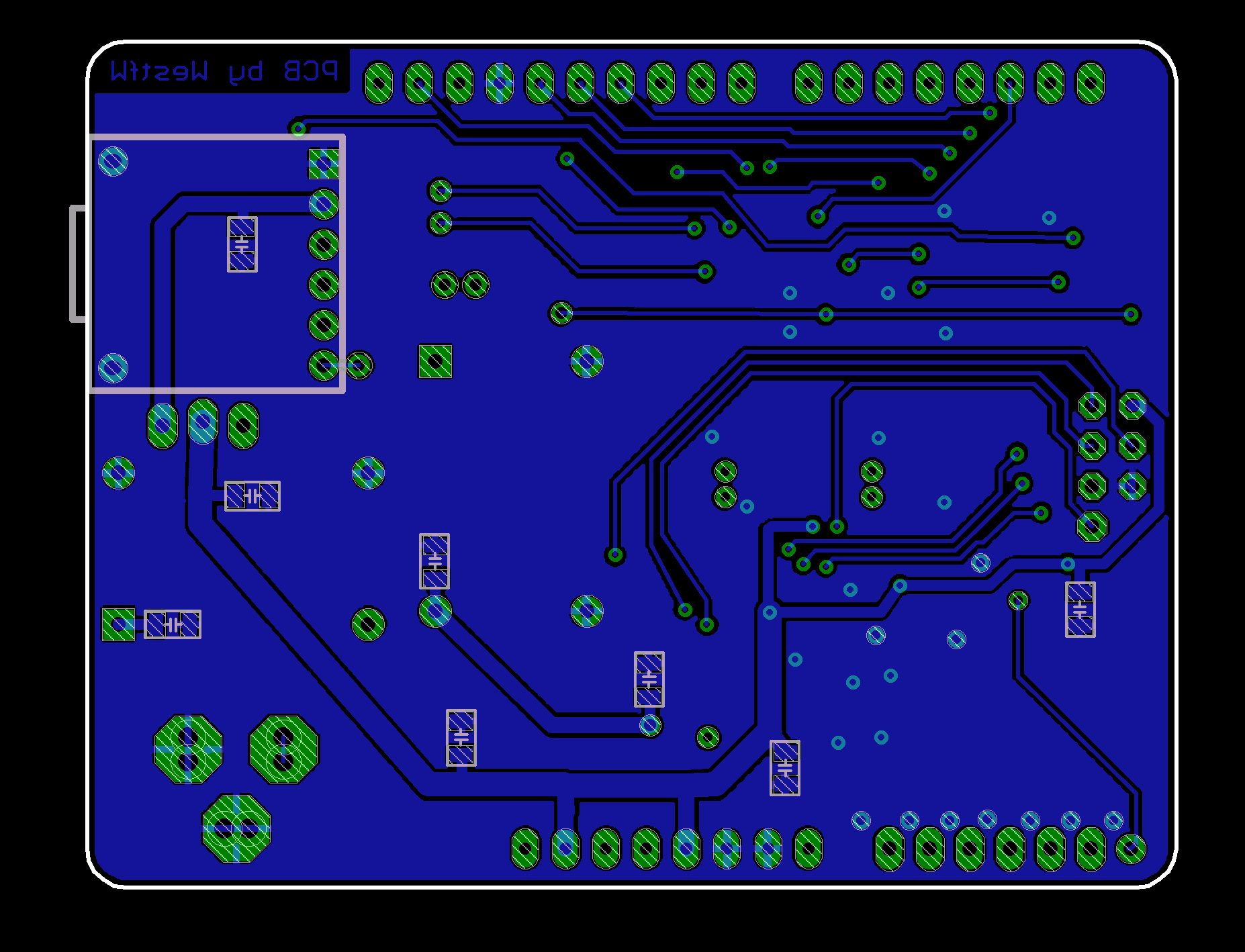
Added pads for most of the "unused" signals. Not very big pads, but better than trying to attach wires directly to the lqfp, if you really need one extra signal...
Those SMPS modules are tiny. Theoretically, the board top layer is left blank underneath them, so that if desired one could replace them with "cheaper" linear regulation circuits. But there isn't enough room for a full-sized TO220 footprint. Also, the pins on the modules I have do not seem to be on any particular grid :-(
Added extra bypass caps on the bottom side of the board. There is plenty of room, so...
Freeduino 4809
This is an Arduino Uno Wifi2 derivative (atmega4809) with the WiFi and other "extra" features deleted.