skelly
-
Creating the "Smart" Bit
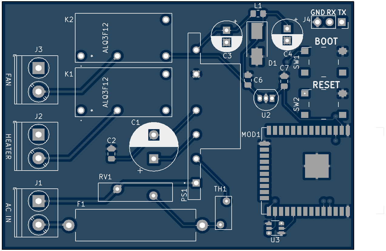
05/26/2019 at 02:04 • 0 commentsShown in smart_boot.pdf is the first iteration of the schematic for the controller. I'm using two ALQ3F12 relays for switching the heater and fan, and a NUD3112 dual inductive load driver, which is specifically made for switching 12V inductive loads (aka the relay coils). This chip is incredibly inexpensive and makes things easier than doing my own relay driving with transistors and diodes. To get the required 12V and 3.3V for the circuit, a PBO-1-S12 AC-DC converter is used. This is a SIP AC-DC converter that is compact and requires a bit of external circuitry, most of which is optional. An ESP32-WROOM-32 is being used as the microcontroller, and will allow for all sorts of connected funtimes. Shown below is an image of the PCB that I'm getting manufactured.
Please ignore the woeful lack of isolation between mains and low voltage sections of the board. I could have done much better, but it'll work. My main goal was to be as compact as possible, since I don't have much space inside of the boot warmer to place the circuitry. I've ordered the boards, all the parts have already arrived, but we'll see if this works!
![]()
-
Disassembly & Reverse Engineering
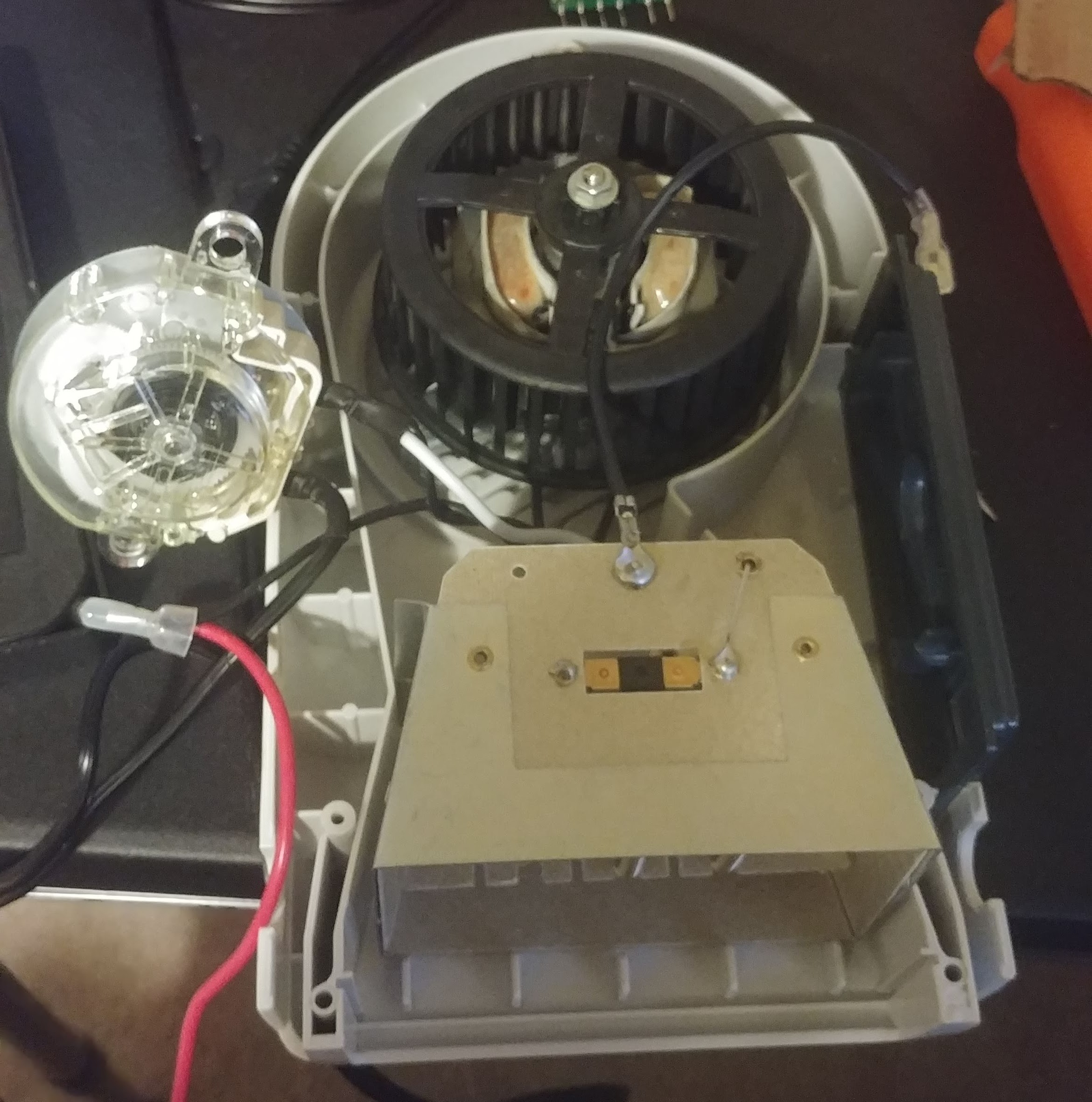
05/26/2019 at 01:47 • 0 commentsThe first step is to figure out what makes the boot dryer tick. Here's a photo of it taken all apart. Visible is the squirrel-cage (plastic) fan, timer switch to the left, and heater assembly at the bottom. The dark grey rectangular piece on the right is the front panel that normally houses the timer switch and a toggle switch for the heater.
![]()
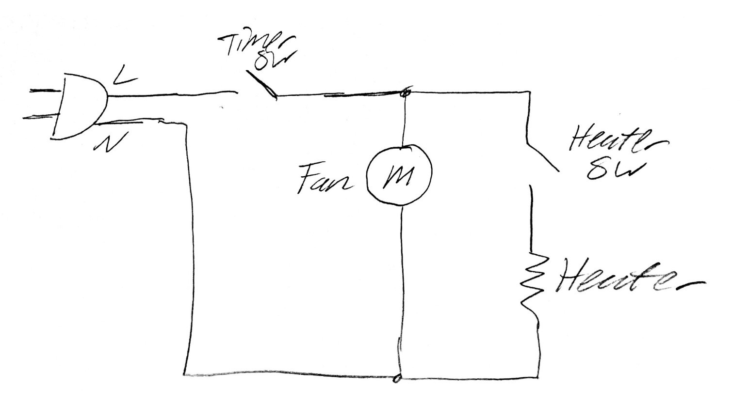
Shown below is a rather crude drawing of the circuit. The timer switch is a timer dial that can be set up to 3 hours. The heater switch is a simple toggle on the front panel of the unit.
![]()
So basically, our circuit will simply bypass these switches and use relays to switch the fan and heater individually.
Internet Connected Boot Dryer
Modifying a Boot Dryer to be controllable via the internet!