skelly
-
Officially complete!
06/23/2019 at 18:33 • 0 commentsThe project is now officially completed!
I got the new PCB's which solve the AC isolation problem and everything is working perfectly now!
The ESP32 is no longer being affected by the fan, everything is working just as designed.
I'm really excited, and will make sure everything is up to date so you can make this yourself if you want!
-
Some Changes Coming
06/16/2019 at 04:14 • 0 commentsSo after discovering the horrible AC isolation problems, I've redesigned the thing slightly and ordered new PCB's. I'll update when they arrive and I've had a chance to test them out!
-
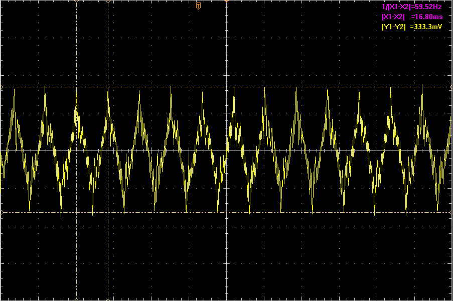
In Which I Learn the Importance of AC Isolation
06/15/2019 at 16:47 • 0 commentsSo this could very well be why the board is flipping out sometimes when I turn on the fan.
This is present on all IO pins, all over the board, everywhere, all the time. Whoops.
![]()
-
It Werks!
06/14/2019 at 23:35 • 0 commentsSo turns out, I made a big mistake.
I didn't realize that RX goes to TX and TX goes to RX, not RX to RX and TX to TX. I was misreading some schematics and was very confused.
But it works!
However, the relay footprints still need fixing (I just bodged it for now), it needs better AC isolation design/fusing, and I'm still not sure why it occasionally browns out. I'm using an 800mA 3.3V regulator and it's drawing, at most, 120mA. Maybe I need bigger capacitors on the power rails.
I've discovered something about this heater - the heater itself is never meant to be on without the fan. If air is not being forced over the heater, it gets incredibly hot and starts to glow and smoke slightly. That's a problem if the fan fails, for sure. I've added code to ensure that the heater is never on without the fan, but still.
I'm going to be testing it for a while to ensure that it doesn't become a fire hazard.
There are a few worries with this thing:
Like I said, I haven't figured out why the 3.3V sometimes drops out, and it can occasionally get into a state where it keeps browning out forever and never comes back up. This could result in a state where the heater is on and the fan is not, which is a hazard.
So yeah, it works! Over the coming hours/days I'll be uploading everything that you would need to recreate this project, along with lots of warnings about possible safety hazards!
-
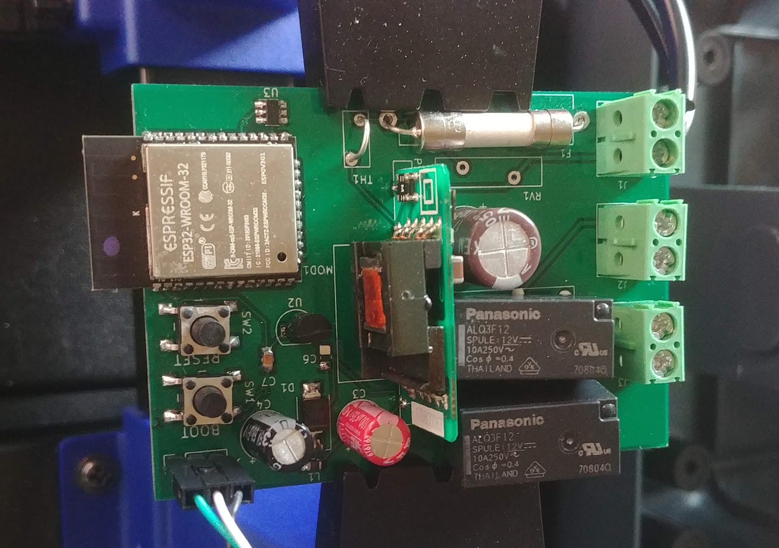
New boards! They don't work!
06/14/2019 at 01:02 • 0 commentsWelp
got new boards that don't work
![]()
- Switch footprints are wrong. The two pins the switch contacts are wired to be across are actually common with each other.
- The relay footprints are wrong. The way it's wired has the switch where the coil is and vice versa. My fuckup on the schematic symbol.
- After bodging the relay problem, the 3.3V regulator drops out for some reason, only giving like 2V
- Also the auto-reset circuitry doesn't work.
Time to test and redesign, wheeeee
-
An incredibly weird issue with ESP32 SSL
06/09/2019 at 05:03 • 1 commentI write this in the hopes that if anyone else has this problem, they might stumble upon this post (or the StackOverflow question I made, or the GitHub issue I created...) to help them since it's so bizarre and incredibly hard to tell what the problem is.
My situation is as such: I have my Mosquitto instance secured with a LetsEncrypt certificate. I want to connect my ESP32 to this instance, so I need the CA root certificate to send along using `WiFiSecureClient`. There are two options.
- Hardcode the certificate into the microcontroller code.
- Use SPIFFS to put the certificate file on the ESP32 and load it dynamically.
I had done the first route successfully, but I really dislike hardcoding things, so I wanted to do the latter.
This ended up being much more difficult than I assumed it would be.
My original code was as such:
if(!SPIFFS.begin(true)) {
  Serial.println("Error mounting SPIFFS.");
}

File file = SPIFFS.open("/root.cer");

if(!file) {
  Serial.println("Error opening the file.");
}

String ca_cert = file.readString();

Serial.println("CA Root certificate: ");
Serial.print(ca_cert);

espClient.setCACert(ca_cert.c_str());
file.close();
Seems simple enough.
Nope.
It didn't work.
I performed every check in the book to see if the hardcoded certificate and the one loaded as a file were the same thing, and they were. Every single equality test I could think of returned that they were, in fact, the exact same string.
However, there's one little note in the Arduino documentation for .c_str():
Note that this gives direct access to the internal String buffer and should be used with care.
Now normally "used with care" applies to situations where you are modifying this string buffer, or trying to use it after the string has been destroyed, etc. Apparently this warning applies to this case as well.
For some reason, using the following code fixed things:
char *dest;

dest = (char *)malloc(sizeof(char) * (ca_cert.length()+1));
strcpy(dest, ca_cert.c_str());

espClient.setCACert(dest);
I have no idea why this works, unless for some reason setCACert tries to modify the pointer it's provided.
But hey, it works. And I can finally stop ripping my hair out over this.
-
Schematic Revision C
06/08/2019 at 14:48 • 0 commentsSo, some changes had to be made since the first PCB didn't work. The problems were:
- The programming didn't function at all. I wasn't able to program the board using the serial connector with only RX/TX (and maybe because it was an FTDI chipset, not the CP2102).
- The relay footprints were totally wrong, I got them from DigiKey and reported the issue, they corrected it and sent me updated footprints.
The changes I made were:
- Use a fully-enclosed AC/DC converter I ordered from eBay. This doesn't require any external circuitry unlike the module I had previously purchased.
- Add auto-reset circuitry.
- Change the programming connector to accept the extra serial pins to provide reset signals.
- Add LED's that were part of the original, but that I left off of the circuit I had manufactured. These LEDs will be external to the board so they are realized using 2-pin connectors.
Check out the Rev C schematic file to see the new and improved design! I've ordered PCB's and hopefully they'll work.
Once I have completely-working PCB's, I'll be providing Gerber/CAD files for them.
-
PCB Progress!
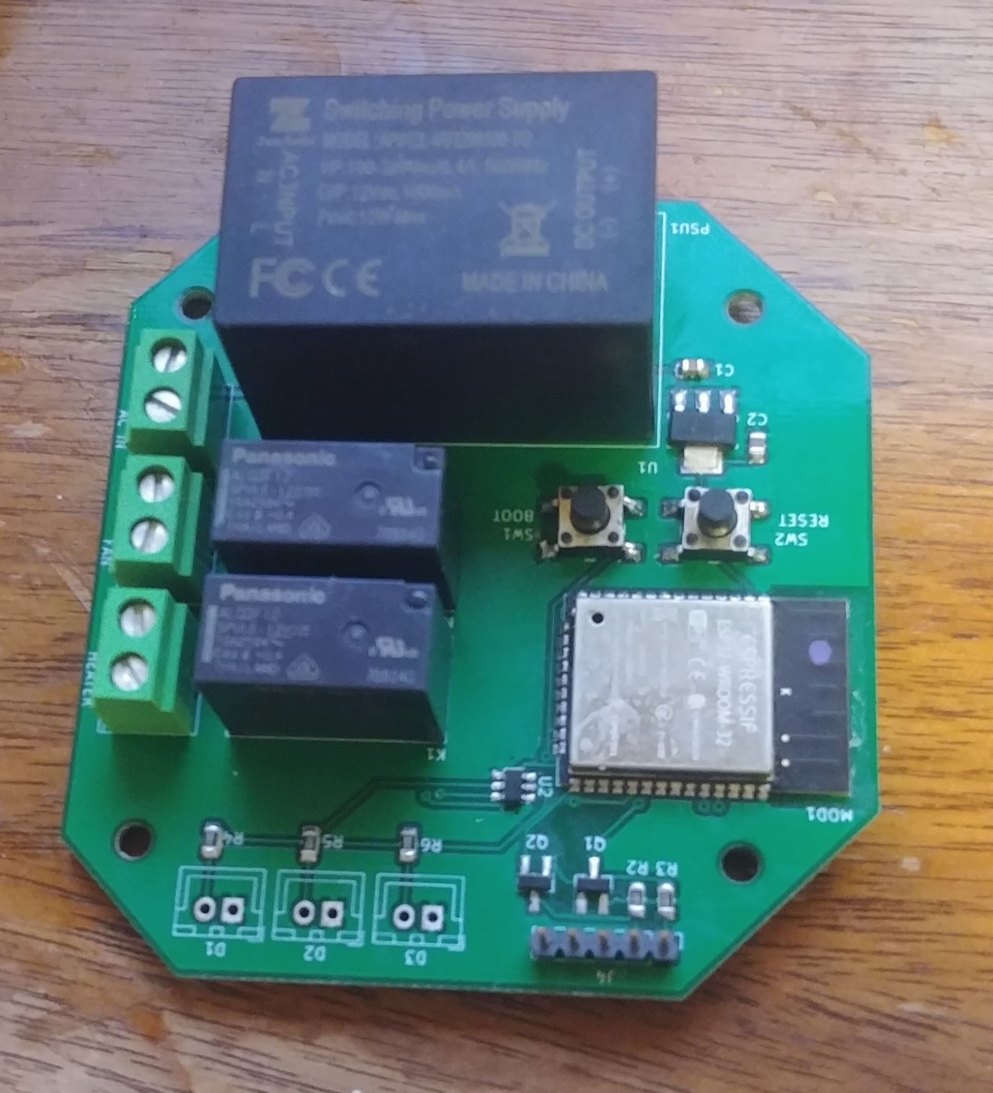
06/05/2019 at 23:31 • 0 commentsSo, I have the PCB's all done and assembled and... they don't work.
![]() ---------- more ----------
---------- more ----------For one thing, the relay footprints were COMPLETELY wrong so the holes don't line up with the pins. Bodge wires to the rescue. Also, the board just won't program. I've tried every combination of the BOOT/RESET switches and it doesn't work.
Something about my reset circuit is borked. So I'm going to make up an auto-reset circuit that many of the ESP32 dev boards use and use that! Since I have to redesign for the corrected relay footprints I might as well.
-
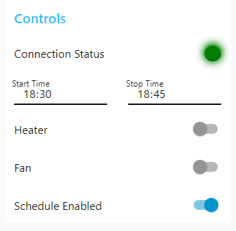
Node Red Complete!
05/29/2019 at 00:58 • 0 commentsSo, implementing the Node Red flows for this project is completed! See the flows.json file for importing them yourself. Here's the dashboard!
Keep reading for how it's all done...
---------- more ----------First, some prerequisites: You have to have Node Red installed and some kind of MQTT broker (I use Mosquitto). You'll also need the "node-red-dashboard" and "node-red-contrib-ui-led" packages for Node Red.
Fair warning, you should probably be fairly familiar with Node Red before diving into how this all works. If you're not: Good luck! Here be dragons!
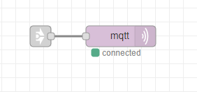
This project is comprised of four separate flows that join together in this one magical tiny flow: The MQTT sender.
So tiny! It takes in all the stuff from every other flow that must be sent via MQTT to the ESP32 in the Dryer. From now on, I'll be referring to this ESP32 as just the Dryer.
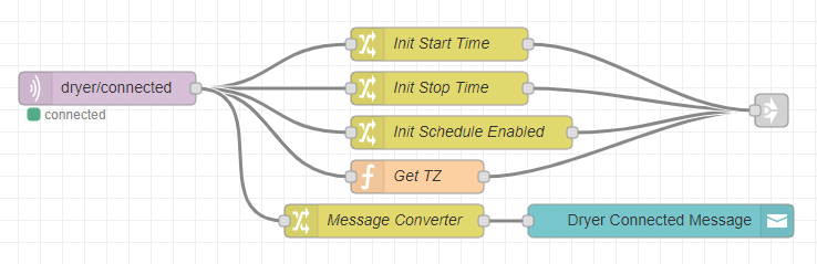
The second flow is shown here. This one is responsible for starting up and initializing the Dryer.
When the Dryer boots up, it is a blank slate with no idea as to what the schedule start/end times are, if the schedule is enabled, and what the current timezone is. When the scheduling values are changed (start/stop time, scheduling enabled), they are stored in the Node Red Global context. Here they are retrieved from that Global context and sent to the Dryer. Similarly, the timezone is found with Javascript and used so that our Node Red dashboard and our Dryer are on the same page in terms of what time it is. Again, all these MQTT messages are routed to a Link to the main MQTT sender flow (above).
We also create a Dashboard notification to notify the user when the Dryer initially connects.
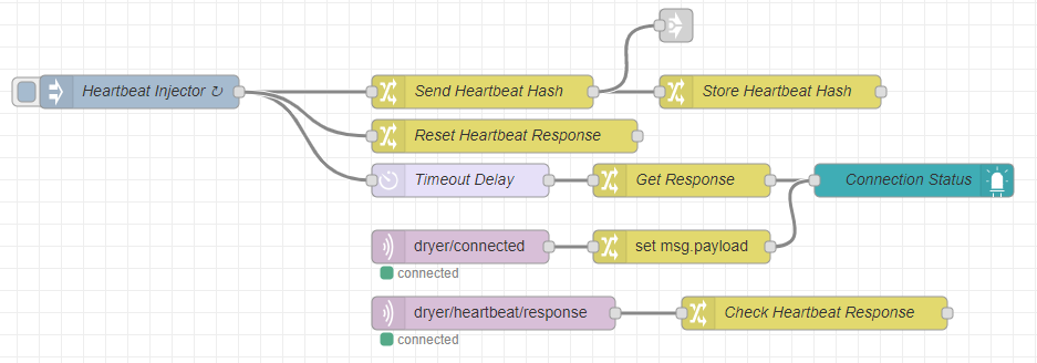
Next, we have the Heartbeat processing flow:
This is a bit more complicated, but here's how it works:
- Every 20 seconds, the Heartbeat Injector fires.
- This sends a "hash" (a random number) to the Dryer via MQTT, sets a "Heartbeat Response" value to false, and starts a delay timer.
- The delay timer runs for 250ms and once it expires, uses the "Heartbeat Response" value to change a Connection Status LED on the dashboard.
- If the Dryer responds to the Heartbeat request, it sets the "Heartbeat Response" value to true.
Effectively, this creates a setup where we ask for a response, wait 250ms and if we don't get a response, we're pretty sure the device isn't connected. We also force the dashboard LED to show that the device is connected when it initially connects.
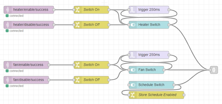
The next flow is for the various switch controls on the dashboard.
This one's also quite complicated. First, here's what happens when you flip a switch:
- The switch sends an MQTT message to the Dryer telling it what switch was switched, and what its state is.
- The Dryer performs the requested action (aka, turns on/off the heater/dryer).
- The dryer sends a "success" message after completing the action.
- This "success" message resets a trigger timer. If it weren't reset, the switch would reset to show that the action was not completed successfully.
- This success message also allows the Dryer itself to control the switch states. For instance, when the Dryer reboots, its outputs are both off and once it turns them off, it sends the corresponding messages which update the switches on the Dashboard.
The "Schedule Switch" is simpler - it's for enabling/disabling the schedule functionality. It simply sends a message to the Dryer telling it if scheduling is enabled or not, and then stores the state in the Global context so that we can initialize the Dryer when it starts up.
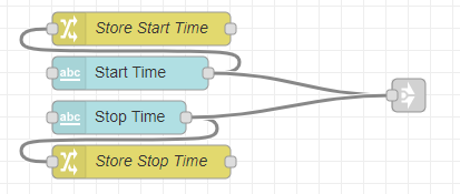
Finally, the last flow. The start/stop time setting controls:
These are just "Text Input" Dashboard widgets which are configured as time entry widgets. It's simple: These just send off the chosen time to the Dryer and also store it in the Global context for initializing the Dryer on boot.
Whew. That was a lot. Thanks for reading if you made it this far, and good luck implementing it yourself if you choose to give it a shot!
I'll be posting the ESP32 Microcontroller code soon enough once I get it cleaned up and make sure I haven't left any passwords lying around in the code!
-
Important Note Regarding This Project & Mains
05/27/2019 at 23:33 • 0 commentsThis project has a (120V) mains input on it. This PCB was also designed with very little mains isolation. If you decide to construct this PCB yourself, be INCREDIBLY CAREFUL. The PCB could be incredibly dangerous if hooked up to mains and you don't know what you're doing.
Be warned.
Internet Connected Boot Dryer
Modifying a Boot Dryer to be controllable via the internet!