Changes in AEMLOVE R9
- renamed to AEMLBLINK R1 because that better fits its function
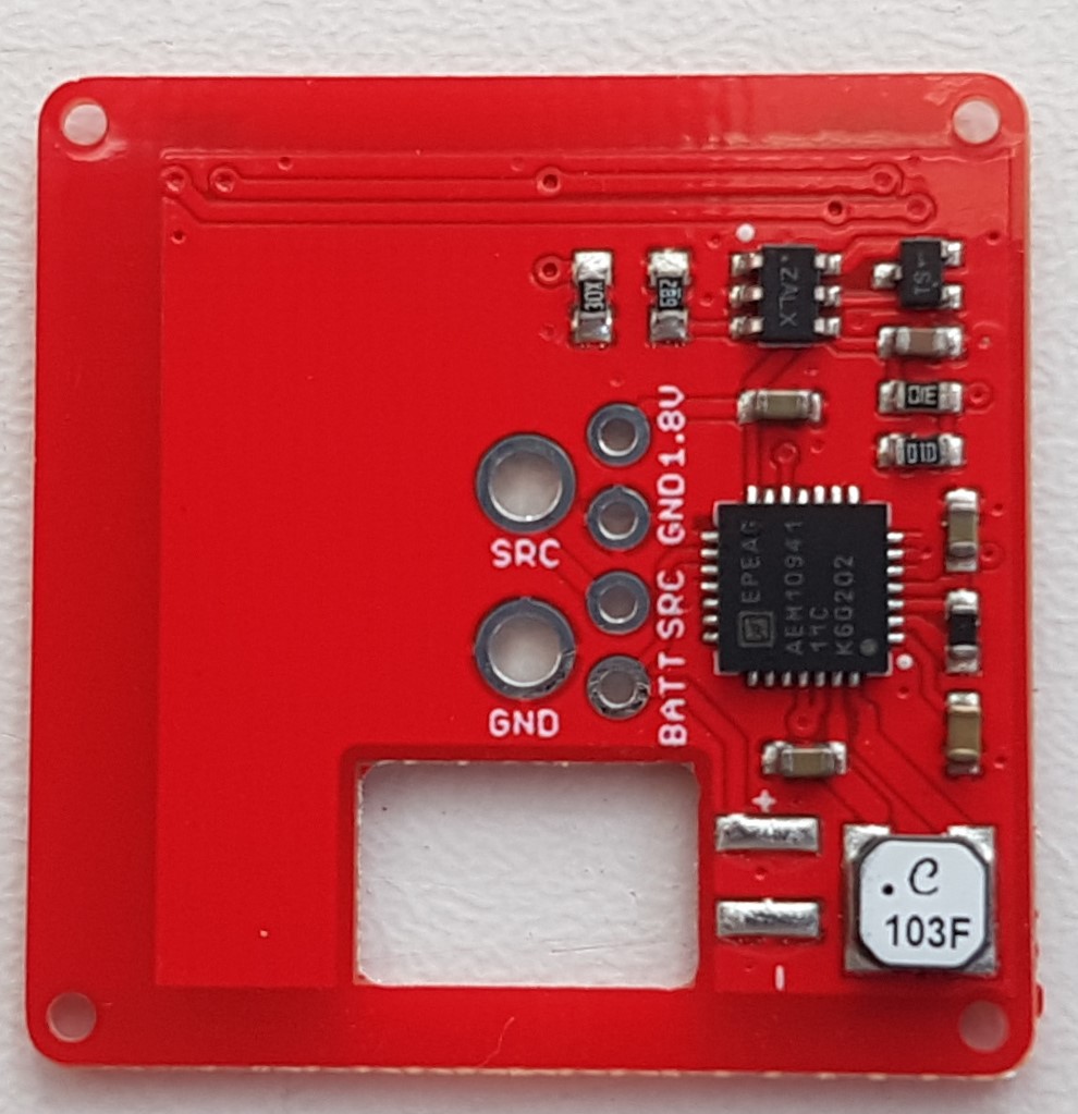
- added 0.1" pitch test pads so the board can be tested after assembly and before super capacitor and solar panel are soldered. Also added one for 1.8V. A user may connect a BLE module or something there.
- removed copper from the left side of the board because BLE module may need copper clearance
- set solder mask oversize to 0.05mm, previously it was 0.00mm
- added clear LED polarity indicators on silkscreen
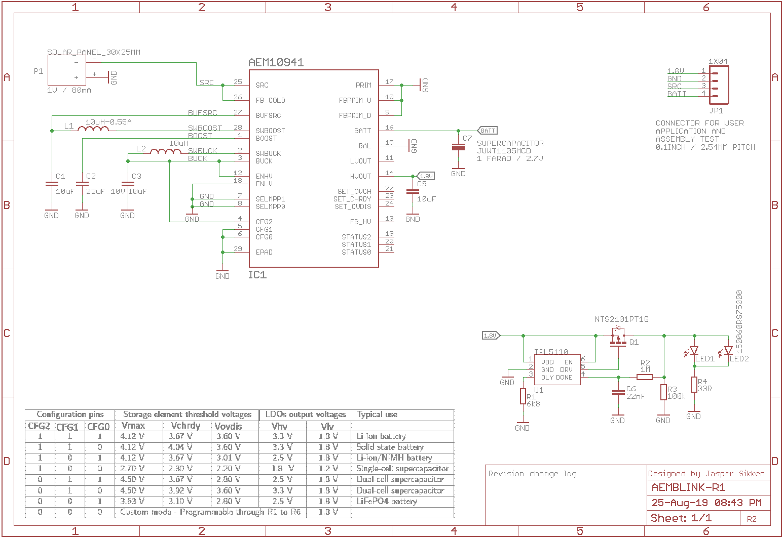
Below is the schematic design

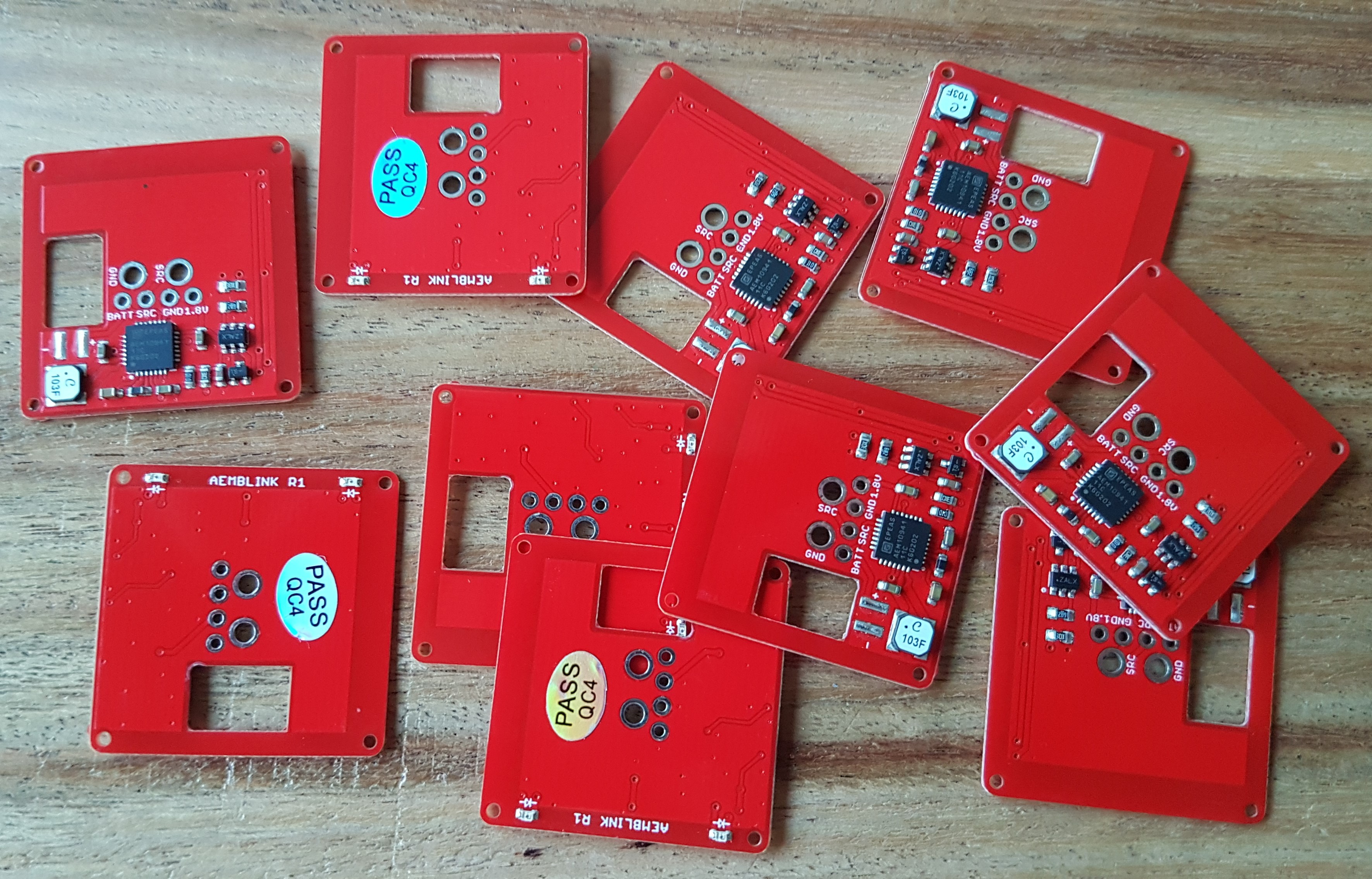
I had 10 boards assembled at Elecrow


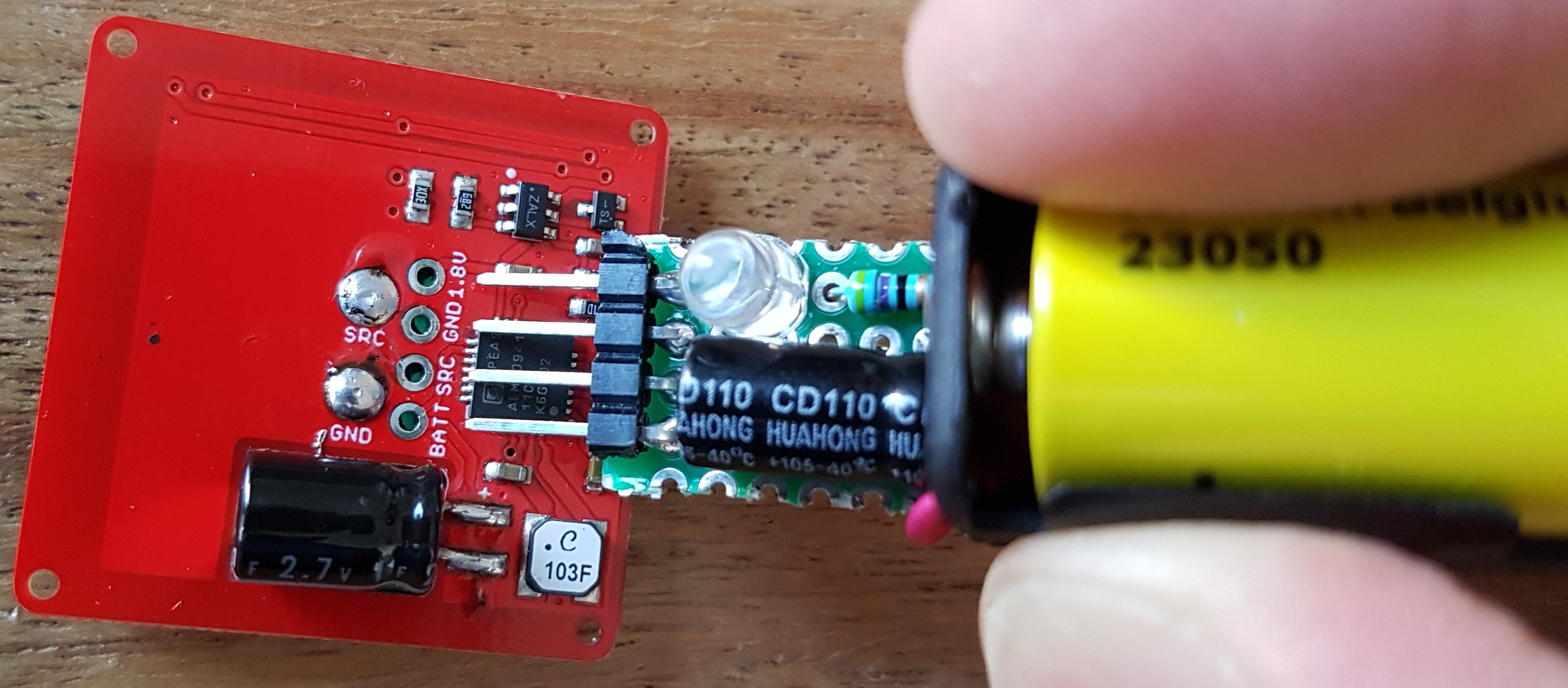
I have created a simple pen shaped PCBA test tool. It is to test the PCBA after assembly and before the solar panel and supercapacitors are soldered. It's just a small perf board with four 0.1" pitch male headers, a 1.5V alkaline battery to simulate a solar panel and a 220uF capacitor to simulate the supercapacitor. When the LEDs on the AEMBLINK board start to blink I know that the AEM10941 and the TPL5110 circuits work correctly. It also has a LED on the 1.8V output from the board. I

The super capacitor is full in 5 minutes in full sun.
Blinking duration is at least 8 hours on a full super capacitor.
I have tested blink duration with with 20, 27, 33 and 43 ohm LED series resistance. All 10 assembled boards blinked for at least 8 hours with a 33R series resistance.
So far what I've learned
- yeah I like the PCB design
- I need to change LED series resistor to 33R on all boards
- next step is selling on Tindie. Some boards I will coat and sell as earrings or necklace, some I will pot with epoxy in a heart shape and sell as necklace, and some I will pot into a silicone piramid shape and sell as desktop gadget
 Jasper Sikken
Discussions
Become a Hackaday.io Member
Create an account to leave a comment. Already have an account? Log In.