Designing a solar harvesting blinking gadget
Based on earlier solar harvesting projects I wanted to design a solar harvesting gadget
Based on earlier solar harvesting projects I wanted to design a solar harvesting gadget
To make the experience fit your profile, pick a username and tell us what interests you.
We found and based on your interests.
Because I want the brightest flash on my solar harvesting blinky with Lithium Ion Capacitor I have ordered 5 green LEDs from Farnell. I have tested them at 5.6uA DC current and compared to InfiniLED which takes 5uA on average from the battery.
InfiniLED blinks with 1 ms long pulses at 35Hz which is supposed to perceived brighter than with DC current.
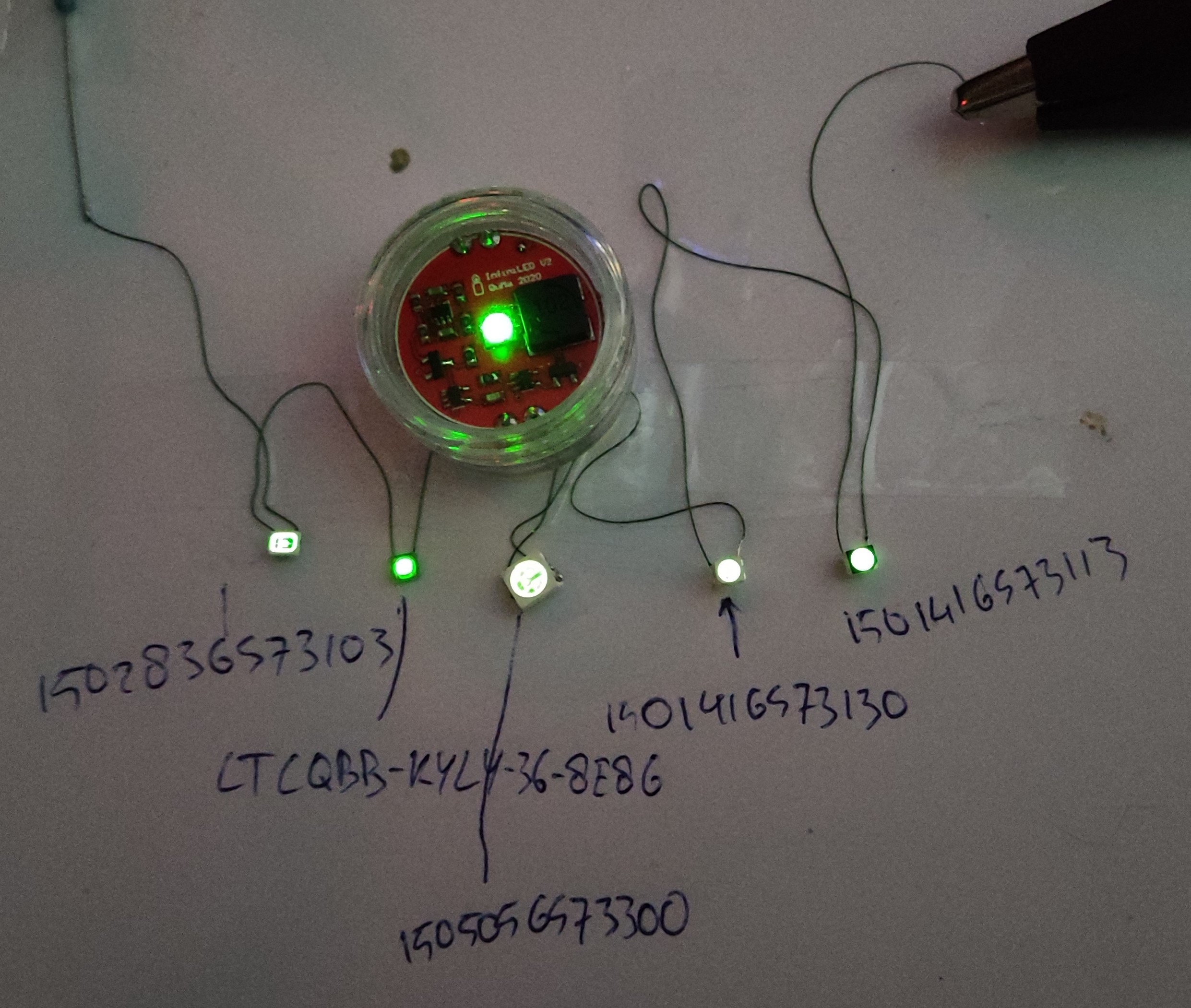
The camera doesn't capture brightness differences well. But I would rank the brightness like this
So the blinking InfinLED indeed looks brighter than the LEDs with DC current.
In the next test the current is 2mA dc.
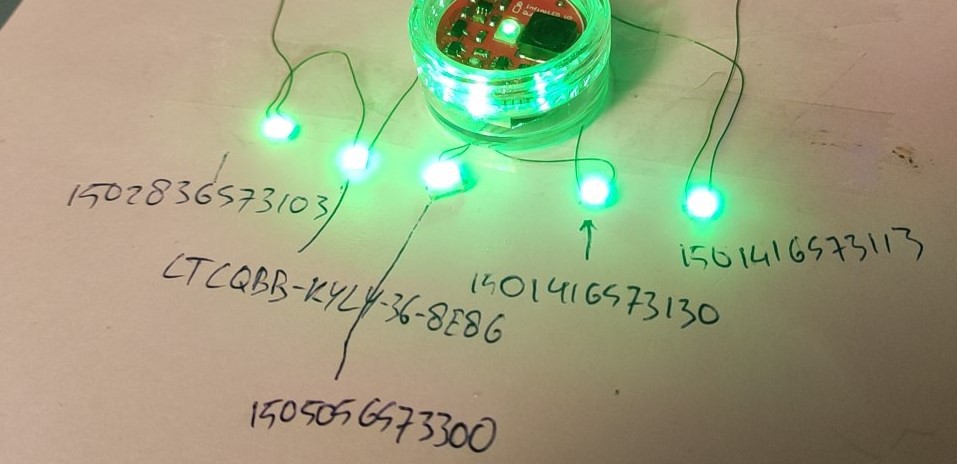
I see little difference, I think 150141GS73113 looks brightest. Interestingly it is the cheapest of all, and it doesn't have the highest specified luminous intensity, so that datasheet parameter is not something you can just believe.
I plan to adjust the LDO in my solar harvesting blinky to about 2.45V and use the 150141GS73113 and set LED current to about 2mA using a low value resistor to keep the losses in the resistor low.
So recently I found Lithium Ion Capacitors are a hybrid between Li-ion Battery (LIB) and supercapacitors (or EDLC) and combine best of both worlds. I also found LICs are nolonger expensive and available at large distributors. (I believe in new IoT designs LICs will replace many Li-Ion batteries and supercapacitors.) And recently I learned that green LEDs are much brighter than red or blue LEDs. So it was time to design a new solar harvesting blinky that stores it's energy into a LIC. I altered the old design from a supercapacitor to a LIC storage unit.
The LIC is 30F 3.8V and produced by Vinatech
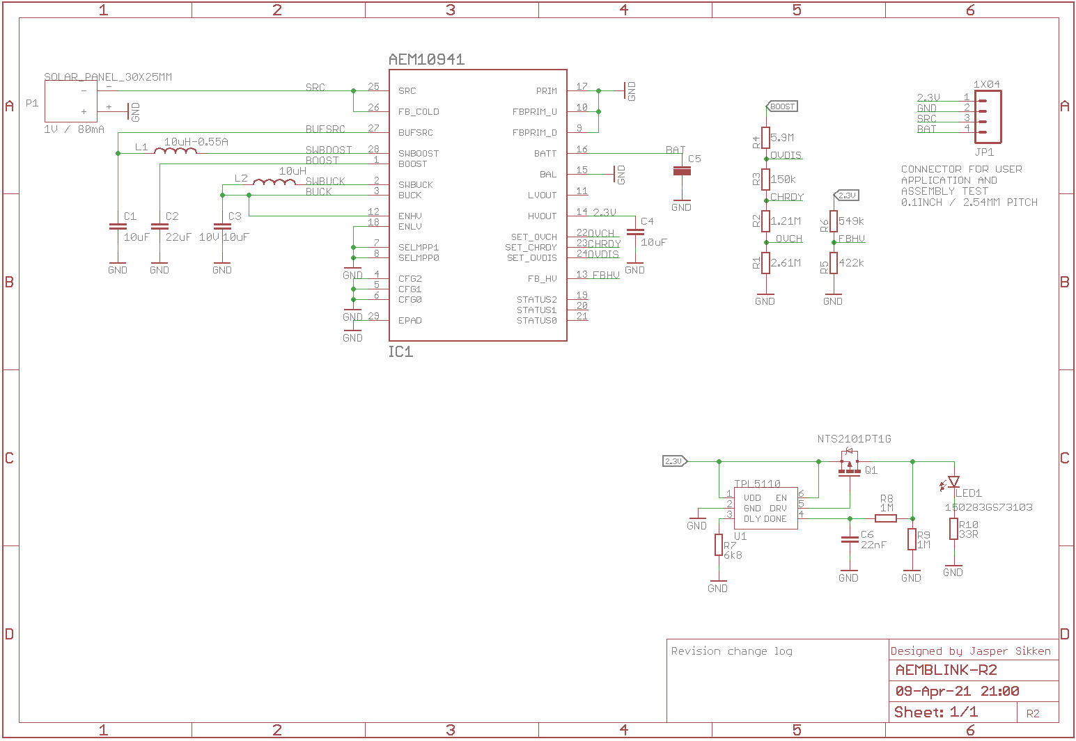
The AEM10941 IC from E-peas is configured to charge the LIC up to 3.8V. The LDO is configured to 2.3V high enough for a green LED. The LDO is enabled when the LIC voltage exceeds 2.6V and disabled when the voltage fall below 2.5V.
For the LED I selected the Wuerth Elektronik 150283GS73103 because of it's very high luminous flux 40 lumen at 150mA. I used the same low power LED circuit as in the previous solar powered blinking pyramid, based on the Texas Instruments TPL5110. That flashes the LED for 15ms every 2000ms. The 15ms is long enough for the human eye to be perceived at maximum brightness and the 2000ms interval draws a lot attention while keeping the duty cycle and average energy consumption low. I measured the current and it is 18uA on average. The assembled board looks like this.
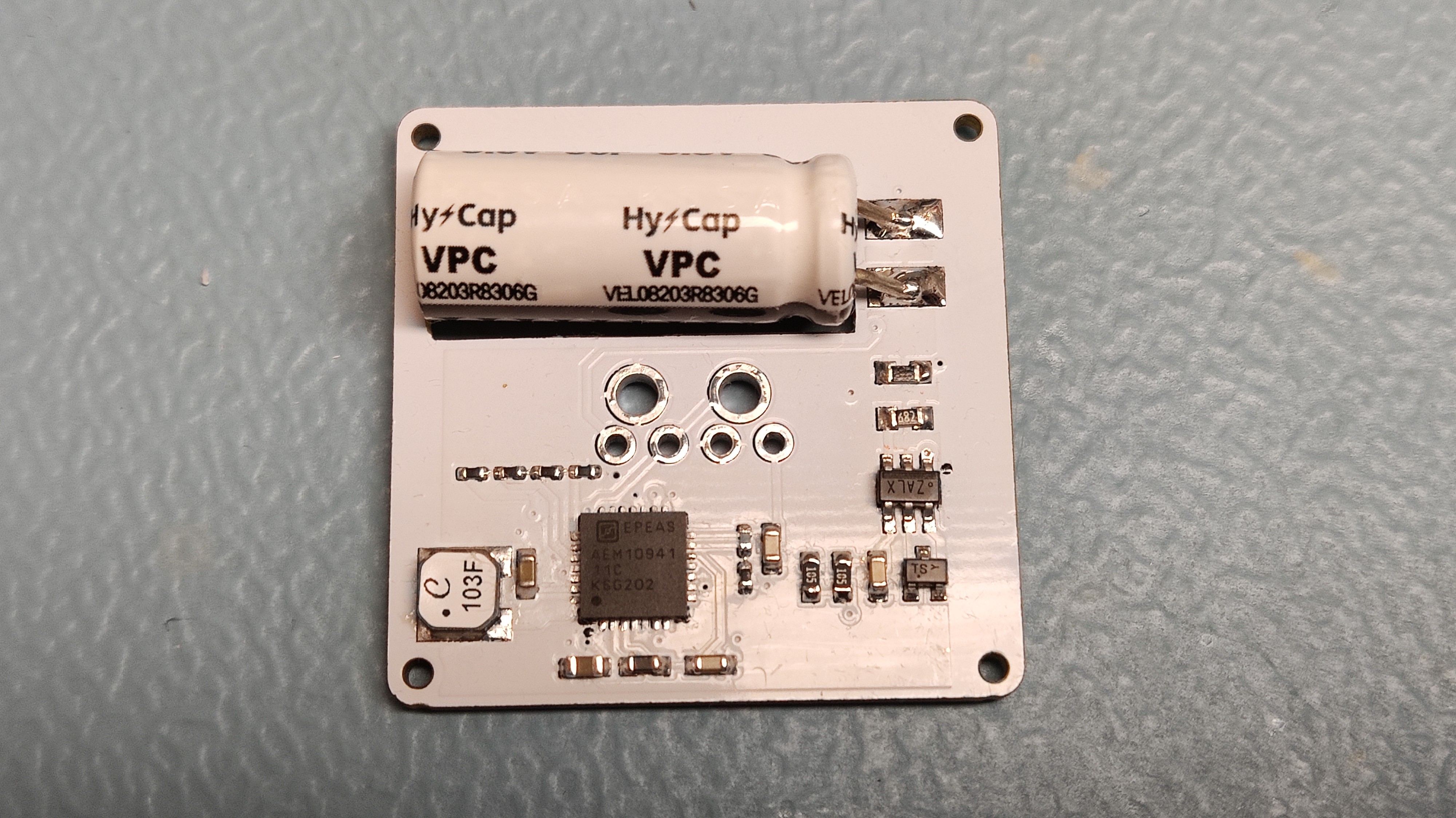
After assembly it blinks like this
The 25x30mm 1V/80mA solar panel charged the LIC at 20uA at 200 lux. So at indoor light levels it will blink forever. And with a fully charged LIC I calculated it will blink for 21 days in the darkness.
After that I put it in a silicone mold with epoxy resin. The resin was mixed gently to reduce the amount of bubbles, poured slowly so that bubbles easily surface. I did not vacuum the resin, but I did remove bubbles from the bottom using a wire, and popped surfacing bubbles using a gas lighter.
And then it looks like this
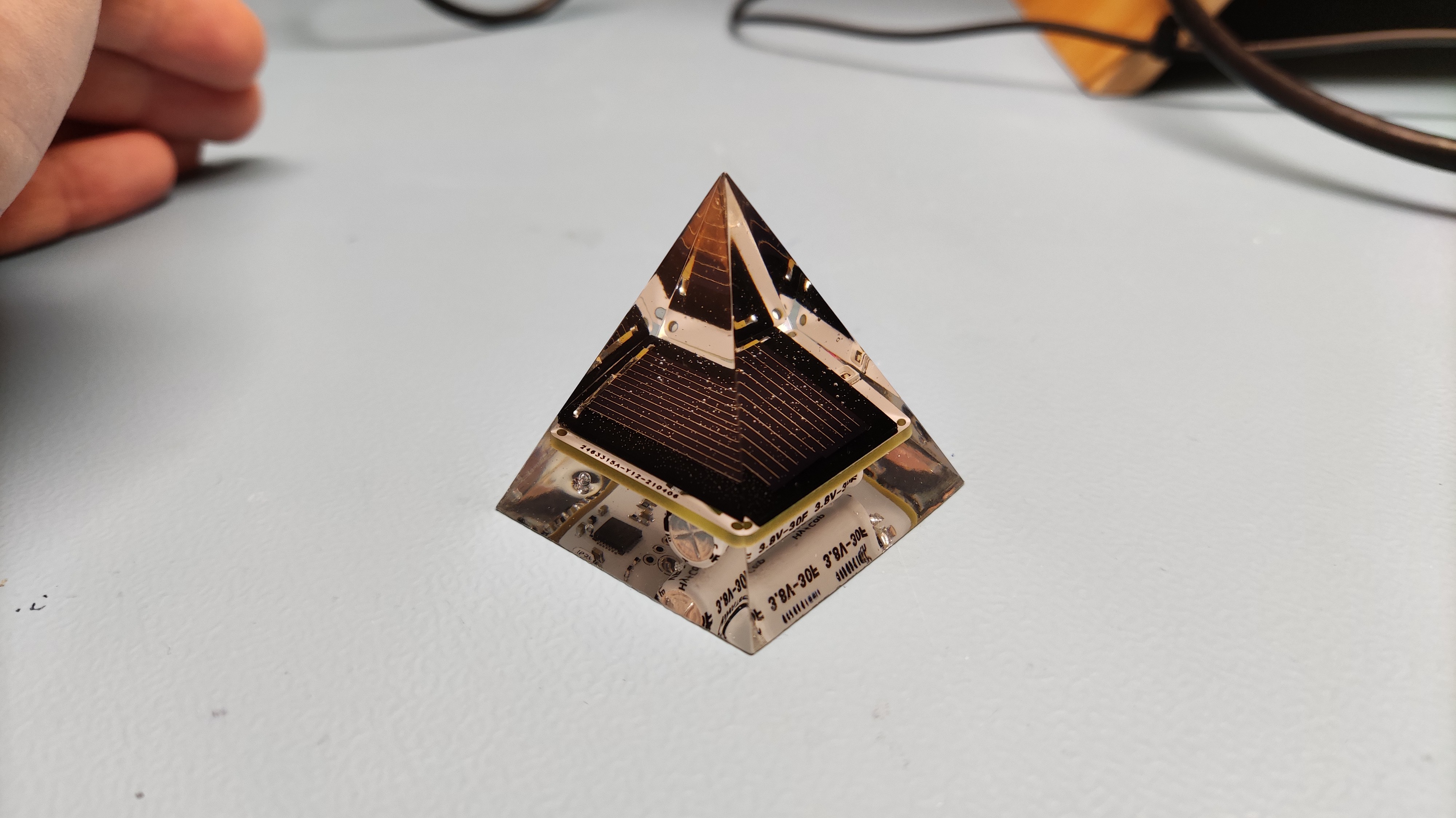
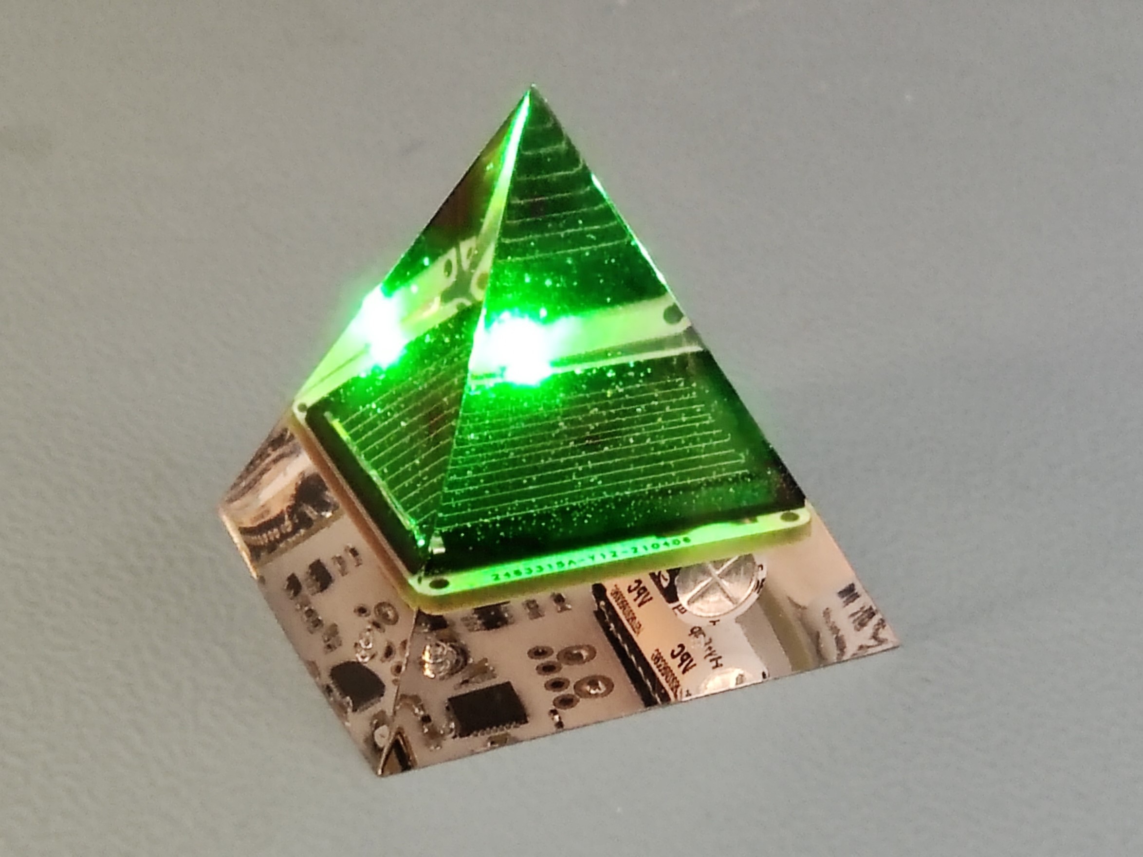
And when it blinks like this. As you can see there are still bubbles, but that's OK because they also nicely disperse the light
On video it looks like this
I am really happy with the design, but it takes a lot of time to assemble, so I usually make less than 10 pieces and give it away as a gift for friends and family. I do not want to sell them online.
Recently I realized that green LEDs are much brighter compared to red LEDs. For example for SML-LX0404SIUPGUSB RGB LED the luminous intensity is 30, 40, 20 mcd at 2mA for red, green, blue respectively.
Then I grabbed a red LED, which I thought was pretty bright (250mcd@20mA), because I selected it for my previous blinky circuit, and soldered it in series with a green LED that I recently selected (1400mcd@20mA), and guess what? The green LED was so much brighter.
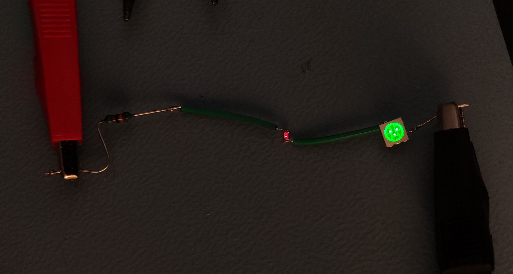
And look at this, at 40uA, it is still pretty bright. Even though the forward voltage is a bit higher, about 2.2V vs. 1.7V for red, it is still much more efficient and the reason is that the human eye is most sensitive to green.
Then I ordered a bunch very bright green LEDs from Wurth
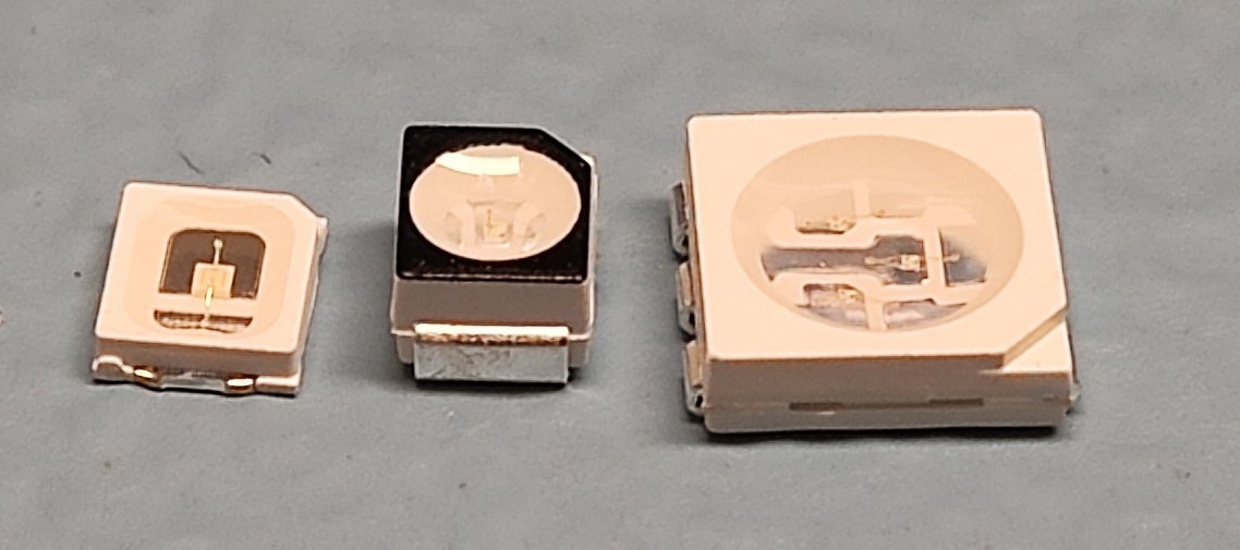
I set the current only 10uA.
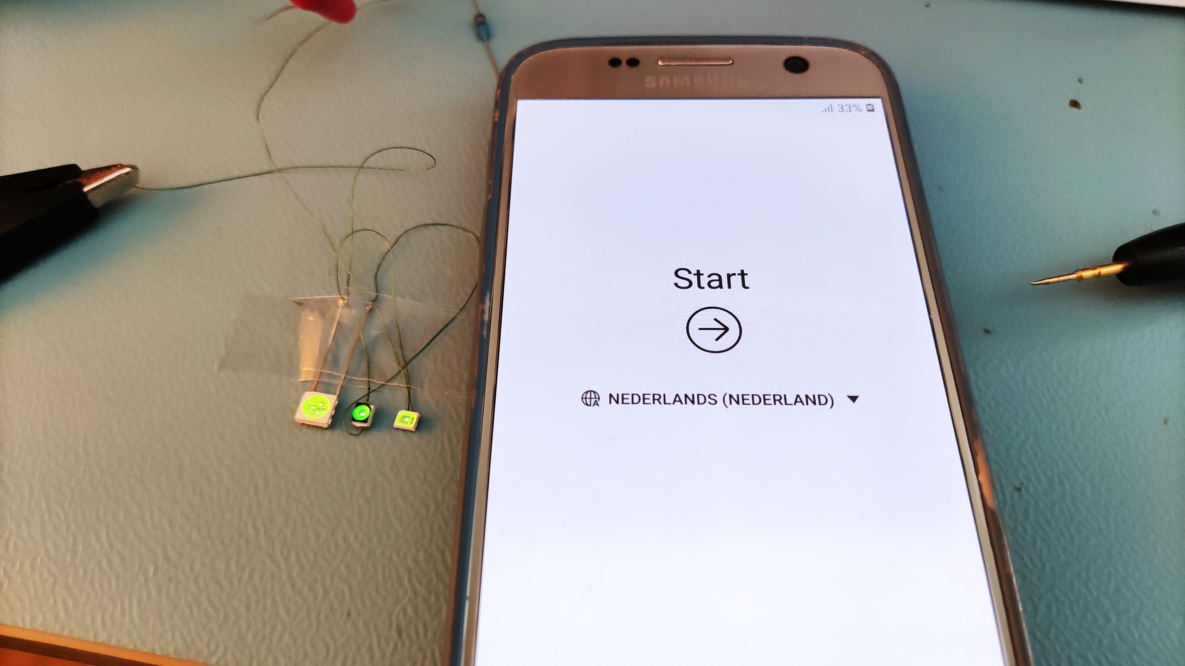
Compared to a smartphone these LEDs at 10uA are very visible. I really need to design a solar powered blinky with green LEDs.
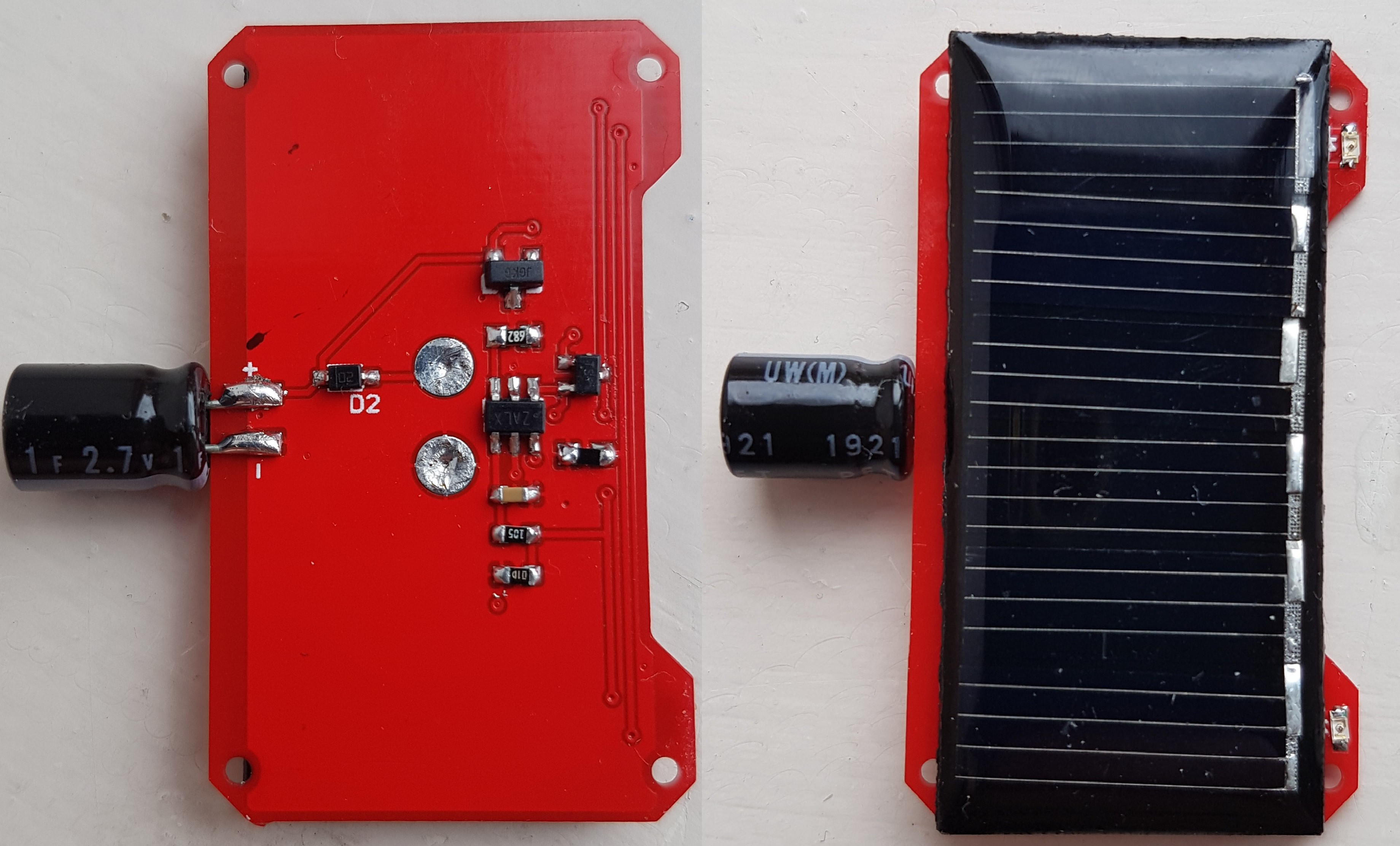
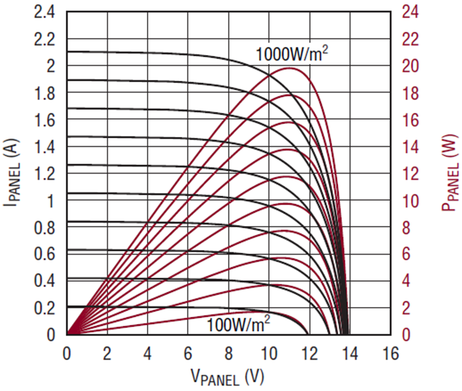
Since solar panel open circuit voltage remains relatively constant under different light levels this time I designed a solar harvesting blinky circuit WITHOUT an expensive solar harvesting IC.
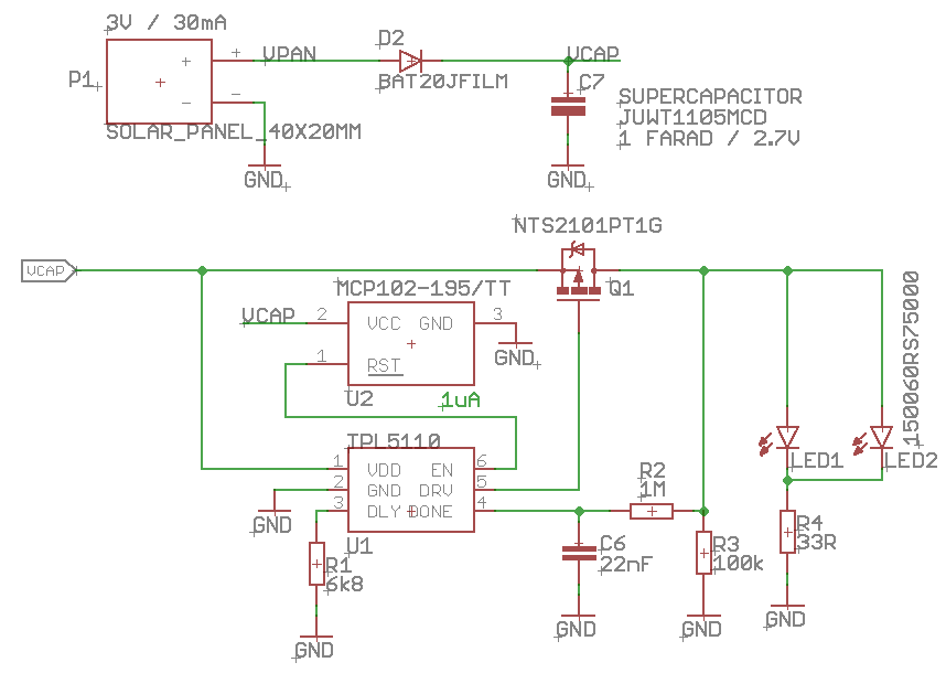
I thought the open circuit voltage of a 3V solar panel under low light would still be high enough for a blinky circuit that needs minimal 1.8V so I designed following circuit. Solar energy goes through the diode into the 2.7V supercapacitor. The TPL5110 blinks the led for 15ms at 2s interval. The MCP102 is a voltage supervisor that disables the TPL5110 below 1.9V.
I learned that the LEDs are super bright when supercapacitor voltage is more than the required 1.8V LED forward voltage.
After a full charge in sunlight the LED stopped blinking early in the night while my previous design with the AEM10941 harvesting IC continued blinking all through the night. To extend battery lifetime I have increased LED resistance from 33 ohm to 330 ohm.
Then I left the solar blinkies in a relatively dark cabinet in my living room for a couple days to understand how they compare. I noticed the old blinkes, with the AEM10941 solar harvesting, restarted blinking in the morning while the new design was not. When I measured the solar panel voltage I found only 1.15V which means it would never charge the mimimal required 1.8V. Then I tested a bare solar panel (wihtout blinky circuit) I also noticed voltage was less than 1.5V. So apparently this solar panel does not have high enough open circuit voltage in low light conditions, while the older blinkies, with the AEM1094 solar harvesting IC were actually harvesting energy. So my idea that the open circuit voltage of a solar panel is high enough under low light conditions failed.
I am really proud of this cheap and simple hack to remove bubbles from epoxy resin.
I bought this $10 mini battery power USB food vacuum.

I bought this $2.2 glass food preservation jar from a local budget store Action.

And I drilled a hole in the middle of the lid using blue tape (painters tape) and a 2mm metal drill, AND safety gloves and safety glasses.
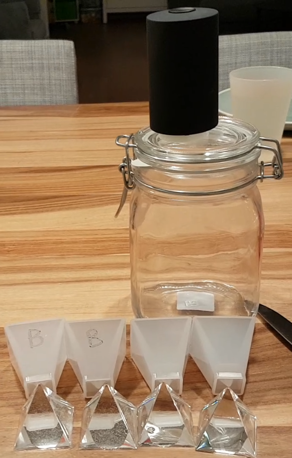
Then I whipped 100 grams epoxy resin to make sure it has lots of bubbles and divided it into two paper cups. One cup I vacuumed for 10 minutes and the other not. After pouring into silicone piramide shape mold it looked like the vacuumed resin had more bubbles and the experiment failed. But 24 hours later, when I removed the epoxy from the mold it was clearly visible that vacuuming actually worked really well.
I think internally it has this vacuum pump that can make -350 mmhg vacuum.
This Saturday I have started selling my boards on Tindie. https://www.tindie.com/products/jaspersikken/aemblink/
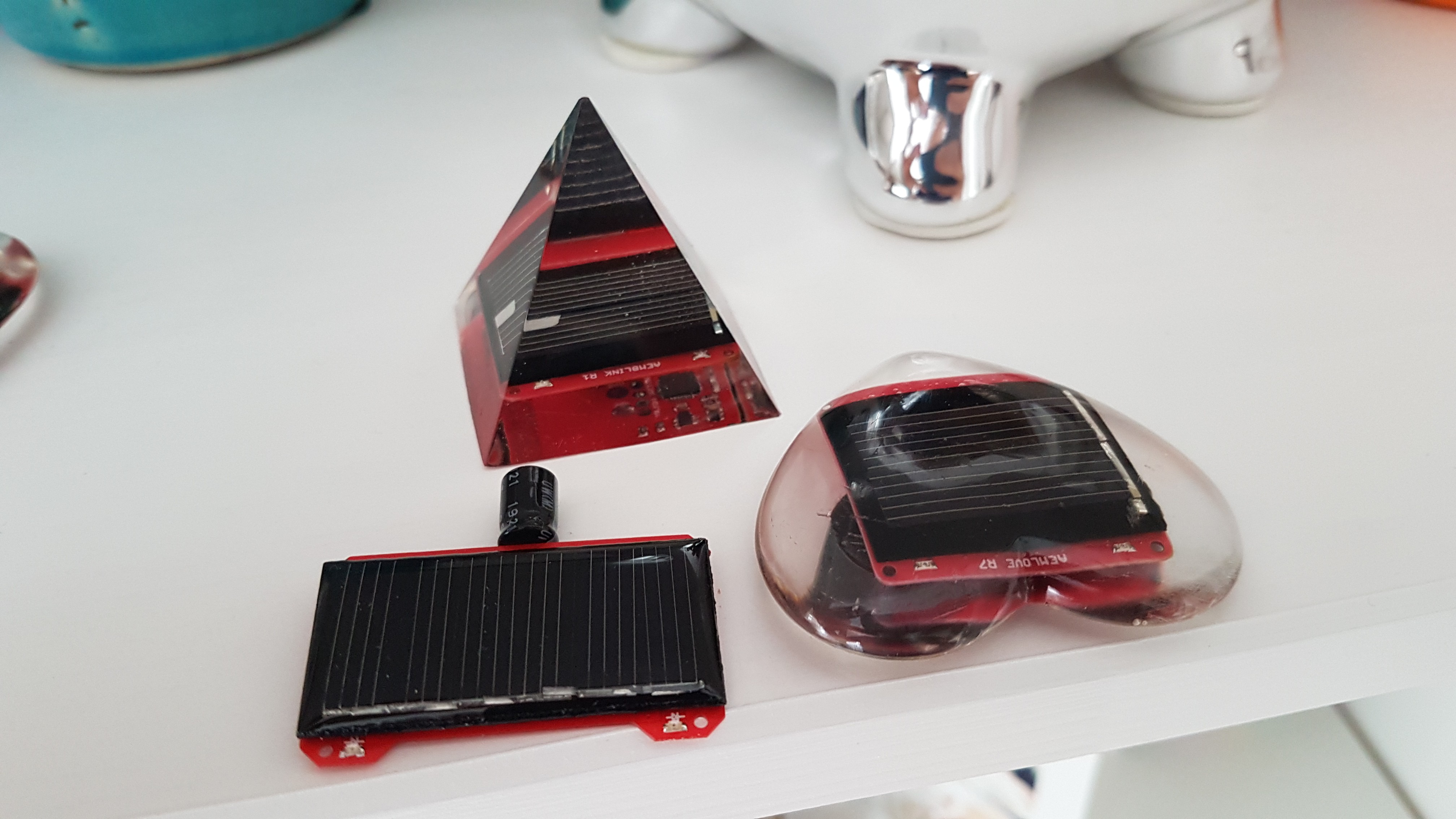
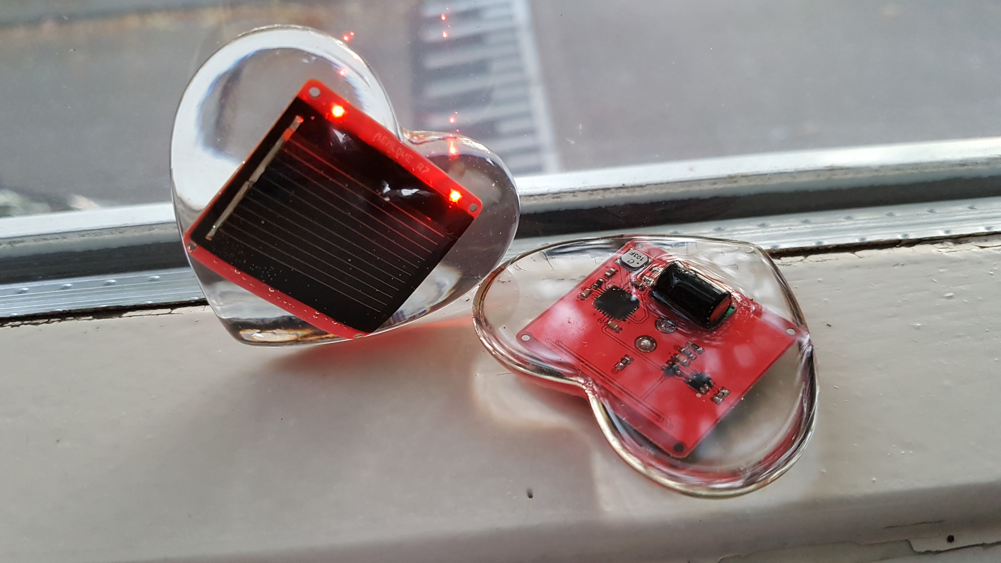
I have poured the PCBA with this epoxy into a silicone piramid and heart shape. The pouring is a delicate process. You need to work very clean, have everything prepared before actually starting. I have cleaned the silicone mold with water and soap and used a can of compressed air to blow out the water, then I have put the mold in the oven at 100 degrees celsius to dry further. On the table I have put couple sheets of protective baking paper. And put everything on it, the bottles of 2 parts epoxy, the bottle of UV stabilizer, a couple disposable cups, a couple wooden stirring sticks, a roll of kitchen towel, a kitchen weighing scale. And then I started mixing the 2 parts epoxy, 50g of part A, 30 grams of part B, 1 gram of UV stabiliser. To avoid bubbles stir slowly and in 1 direction, after 2 minutes pour the stirred mixture slowly in another cup, and mix again, this makes sure that the two parts are well mixed. Then to reduce amount of bubbles I slowly poured the mold 3 quarters full with epoxy and put the electronics slowly in. Then I filled the mold full. Using the stirring stick I tried to remove the bubbles. The curing is slow, you have about 15 minutes to finish, after a few hours it feels hard and after 24 hours curing is done.
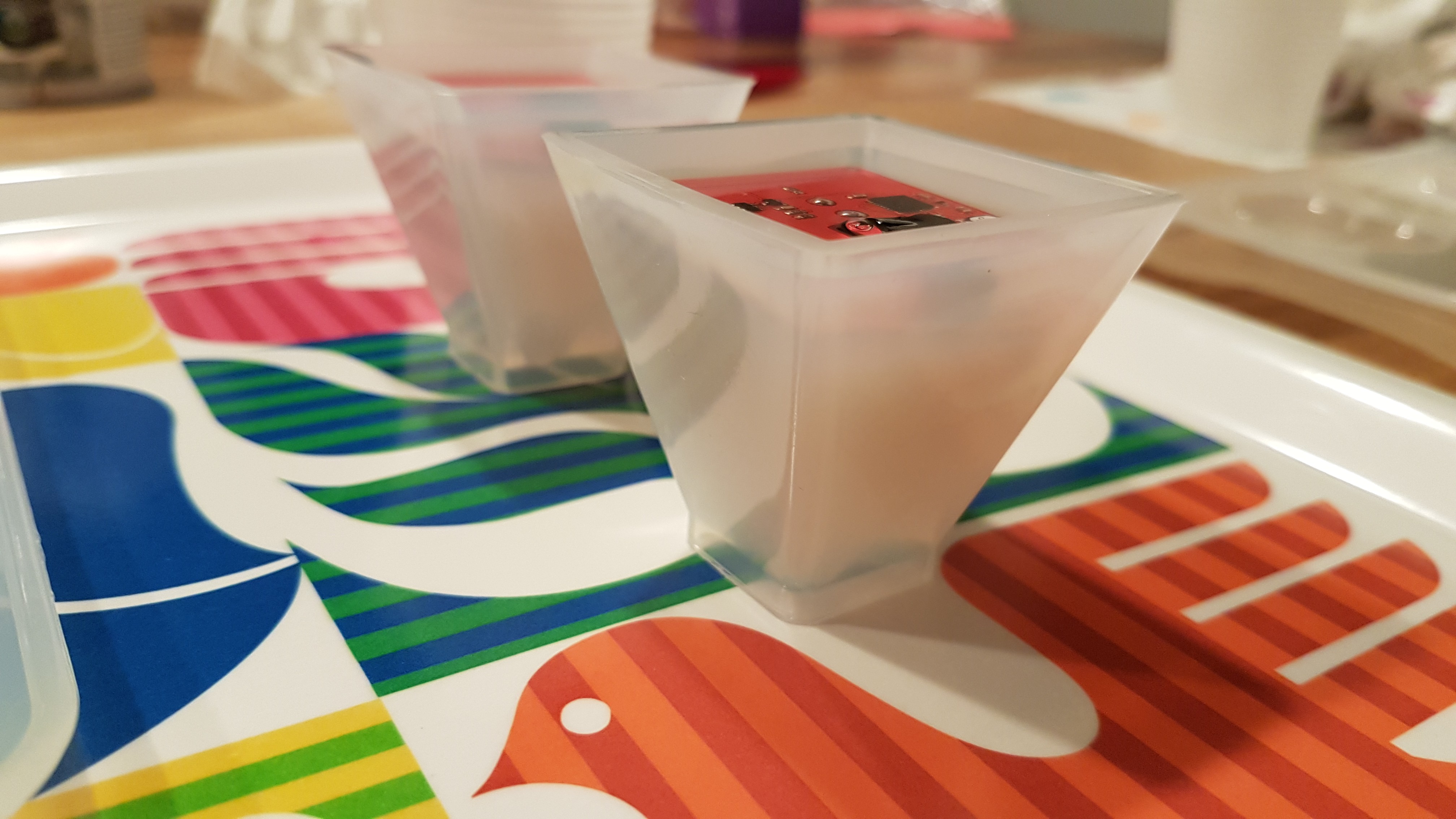
It was quite easy to remove the epoxy from the silicone molds.
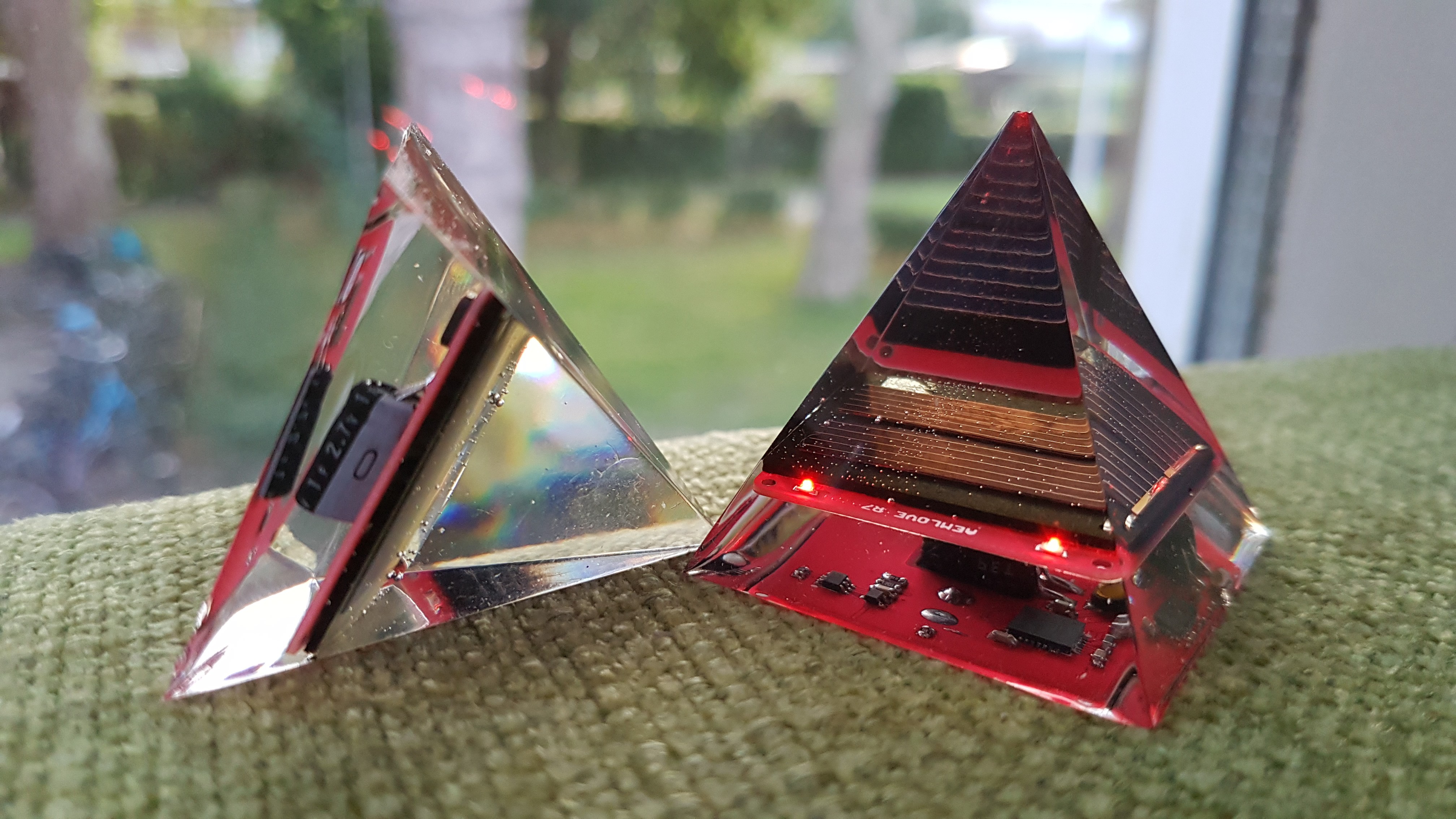
Changes in AEMLOVE R9
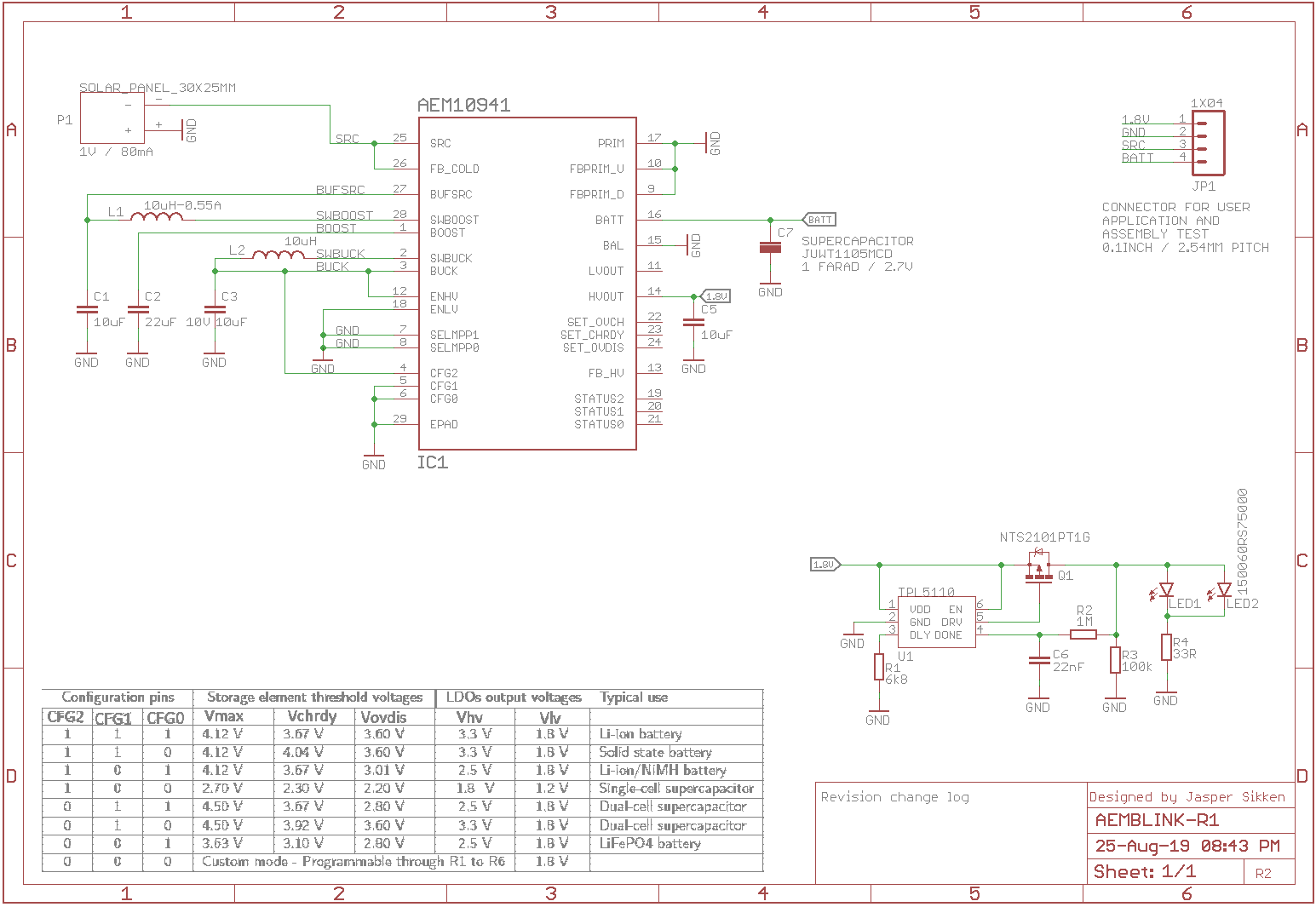
Below is the schematic design
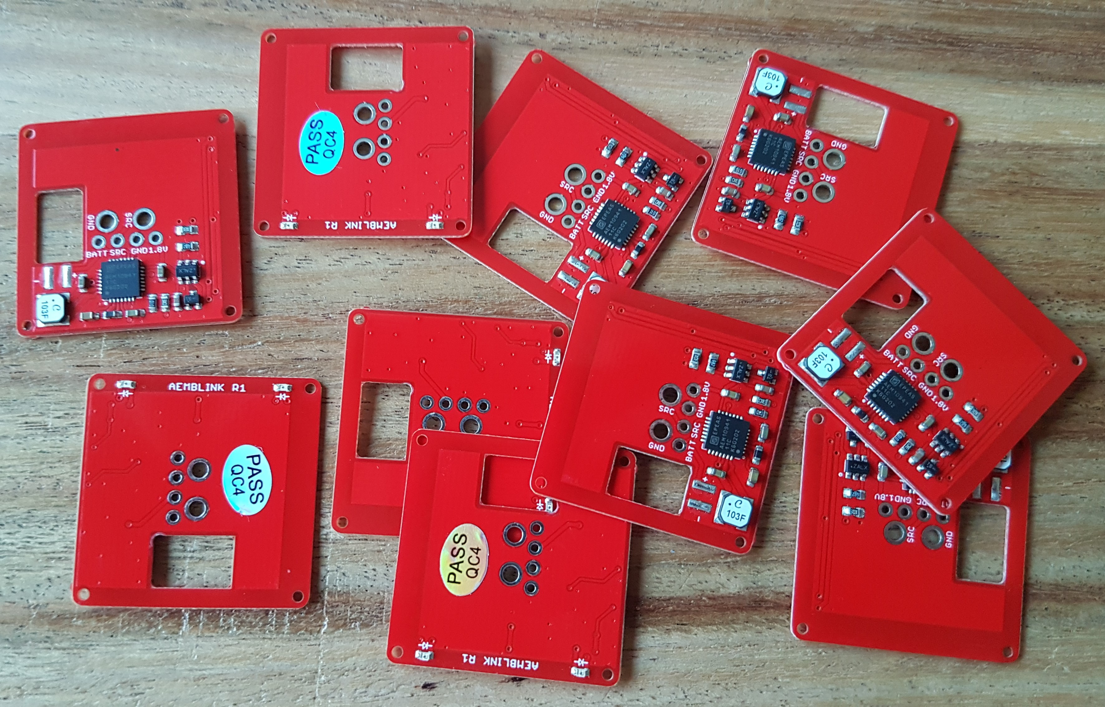
I had 10 boards assembled at Elecrow
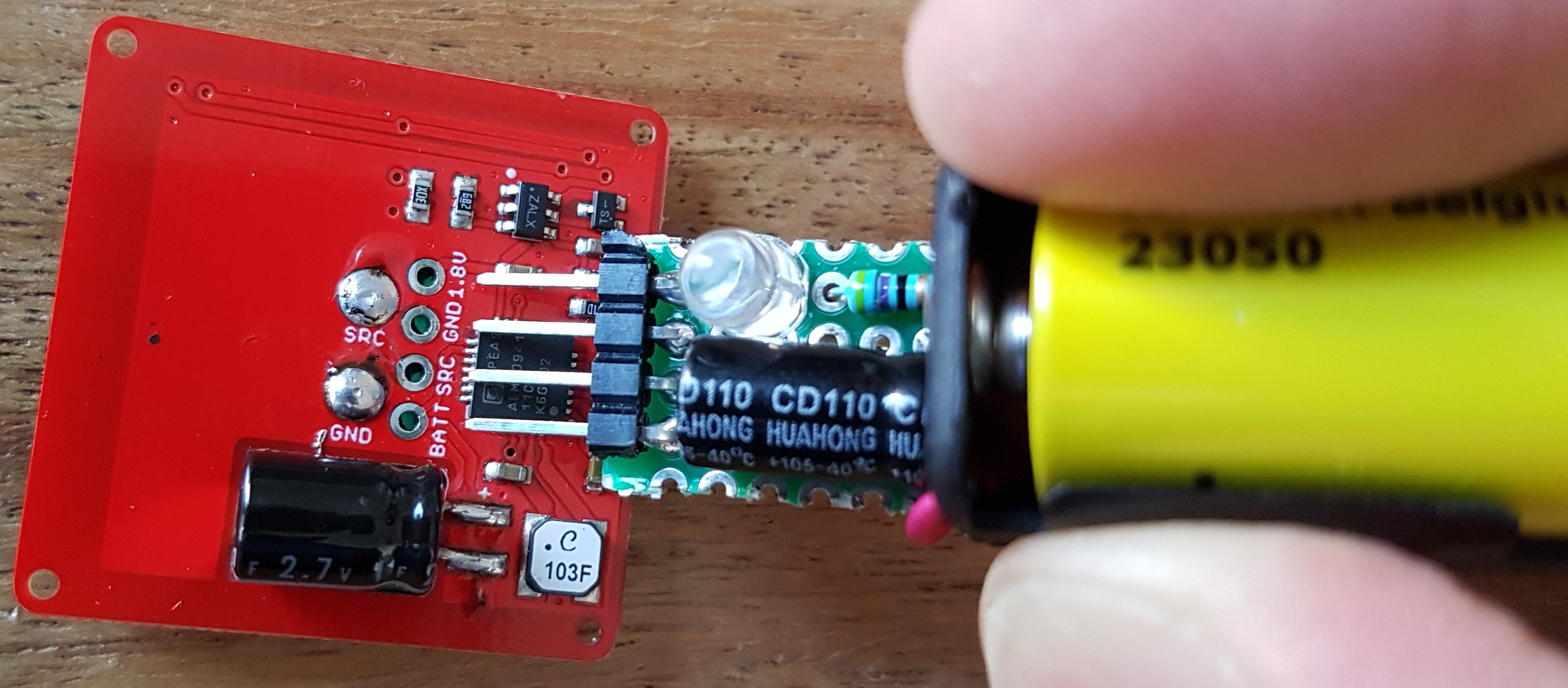
I have created a simple pen shaped PCBA test tool. It is to test the PCBA after assembly and before the solar panel and supercapacitors are soldered. It's just a small perf board with four 0.1" pitch male headers, a 1.5V alkaline battery to simulate a solar panel and a 220uF capacitor to simulate the supercapacitor. When the LEDs on the AEMBLINK board start to blink I know that the AEM10941 and the TPL5110 circuits work correctly. It also has a LED on the 1.8V output from the board. I
The super capacitor is full in 5 minutes in full sun.
Blinking duration is at least 8 hours on a full super capacitor.
I have tested blink duration with with 20, 27, 33 and 43 ohm LED series resistance. All 10 assembled boards blinked for at least 8 hours with a 33R series resistance.
So far what I've learned
I only made a small change because I received a discount code from Eurocircuits and I thought let's try that out. I only moved the TPL5110 circuit to the side to make space for any circuit that an user may want to add. I did not even assemble the PCB.
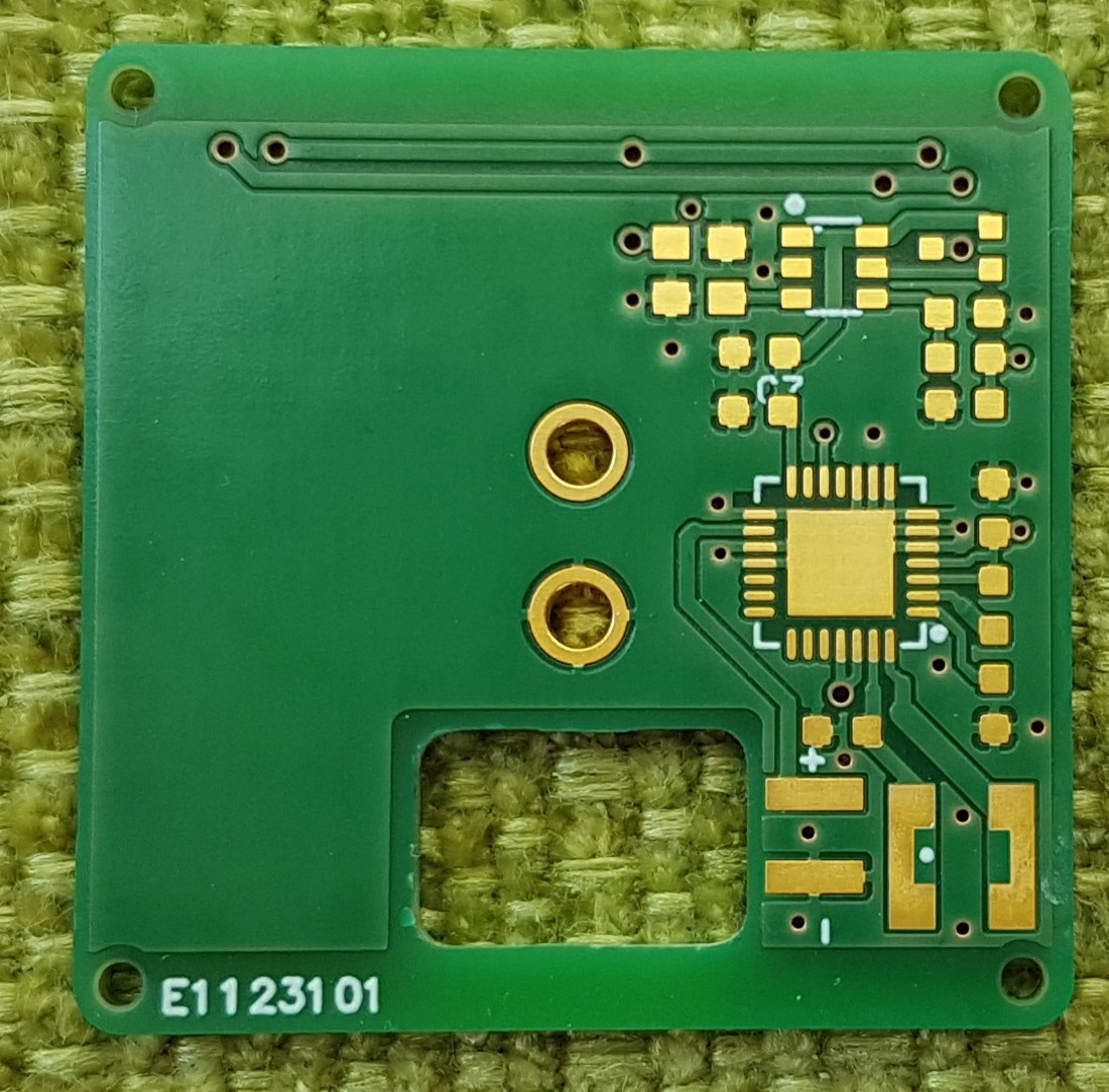
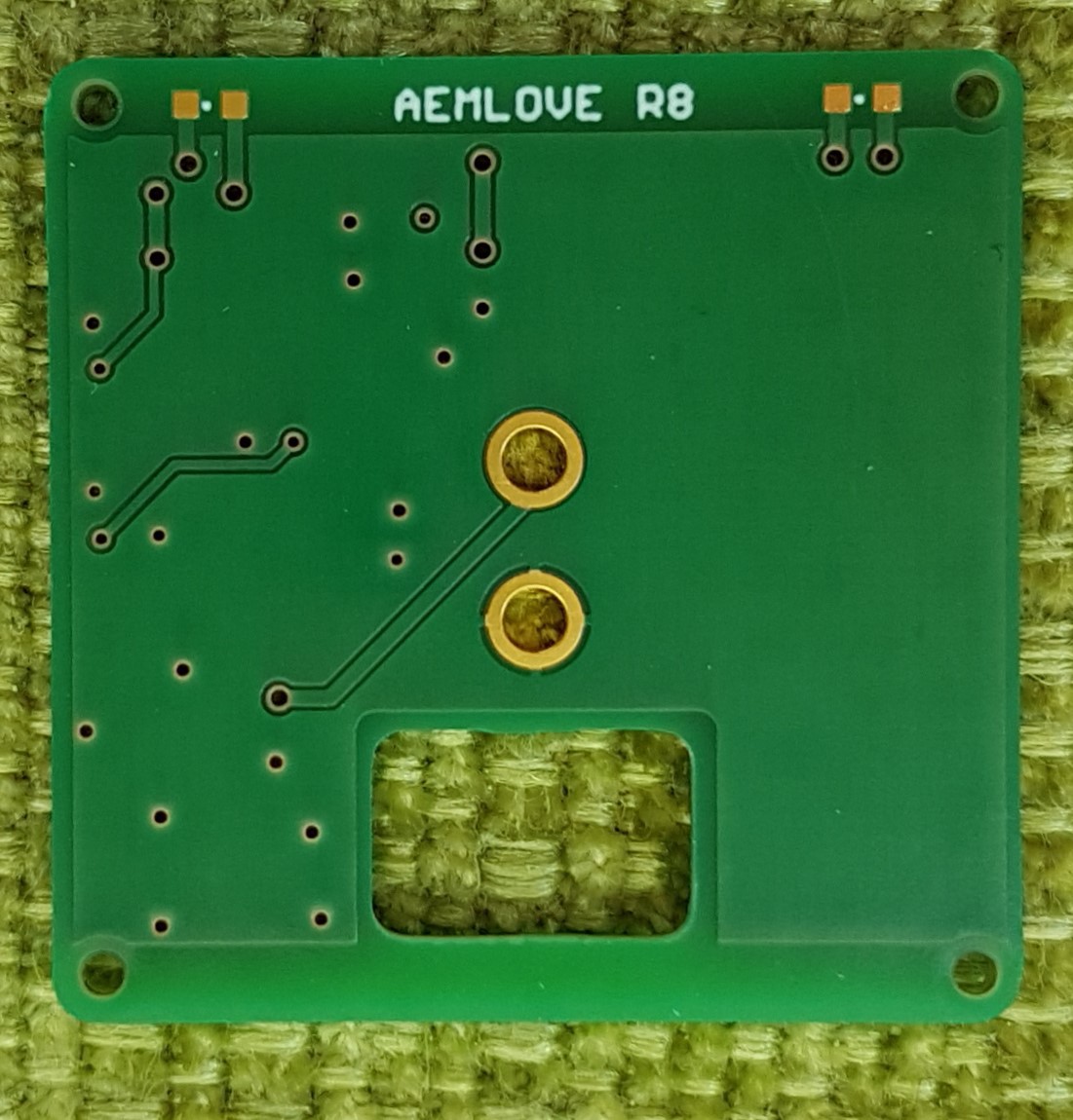
What I've learned
In the previous versions I didn't like the LED blink interval (5s) and the ON duration (80ms) was fixed. I have read somewhere (sorry for no link) that the human eye/brain perceives a 10ms long pulse as full brightness and that flashes with an interval between 0.5s-5s strongly pulls attention. And so I can reduce average consumption while drawing more attention. I found that the TPL5110 "Ultra Low Power Timer with MOSFET driver" that is also for sale on Adafruit and Sparkfun was a great choice to make a bright and low power flash that draws a lot of attention. This is a timer IC ideal for low power applications. Normally it is used to power gate applications and power it ON at a programmable interval. In shutdown it consumes only 35nA. I can choose the blink interval between 100ms and 7200s by choosing a resistor value. This IC is intended to be connected to a microcontroller that sends a DONE signal to the chip when it is done performing its task, for example sending a sensor value wireless, and then it is completely powered off until the timer expires. In my application I don't have a MCU but a simple LED that is powered on. I wanted to feed back the power signal through a RC low pass filter to the DONE pin
Design changes in revision 7
See the schematic below.
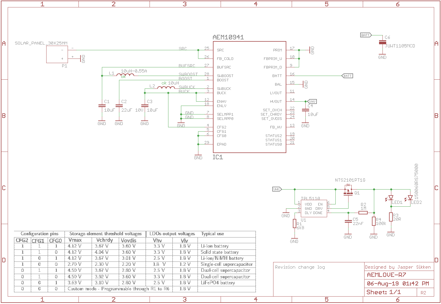
On bottom right you see the TPL5110 circuit. The LED is power gated through a P-channel mosfet. The LED current flows through a 20R resistor and two LEDs in parallel. The power gated signal is fed back through a RC low pass filter to the DONE pin. The DONE pin is considered high when the voltage exceeds 0.7*VDD. With a 1M/22nF the RC time (63%) is about 22ms and close to the desired 10ms. A 6.8kohm resistor sets the interval to ~2seconds. I have added a 100k pull down to the feedback signal to make sure the RC filter capacitor is discharged before it is re-enabled after 2s.
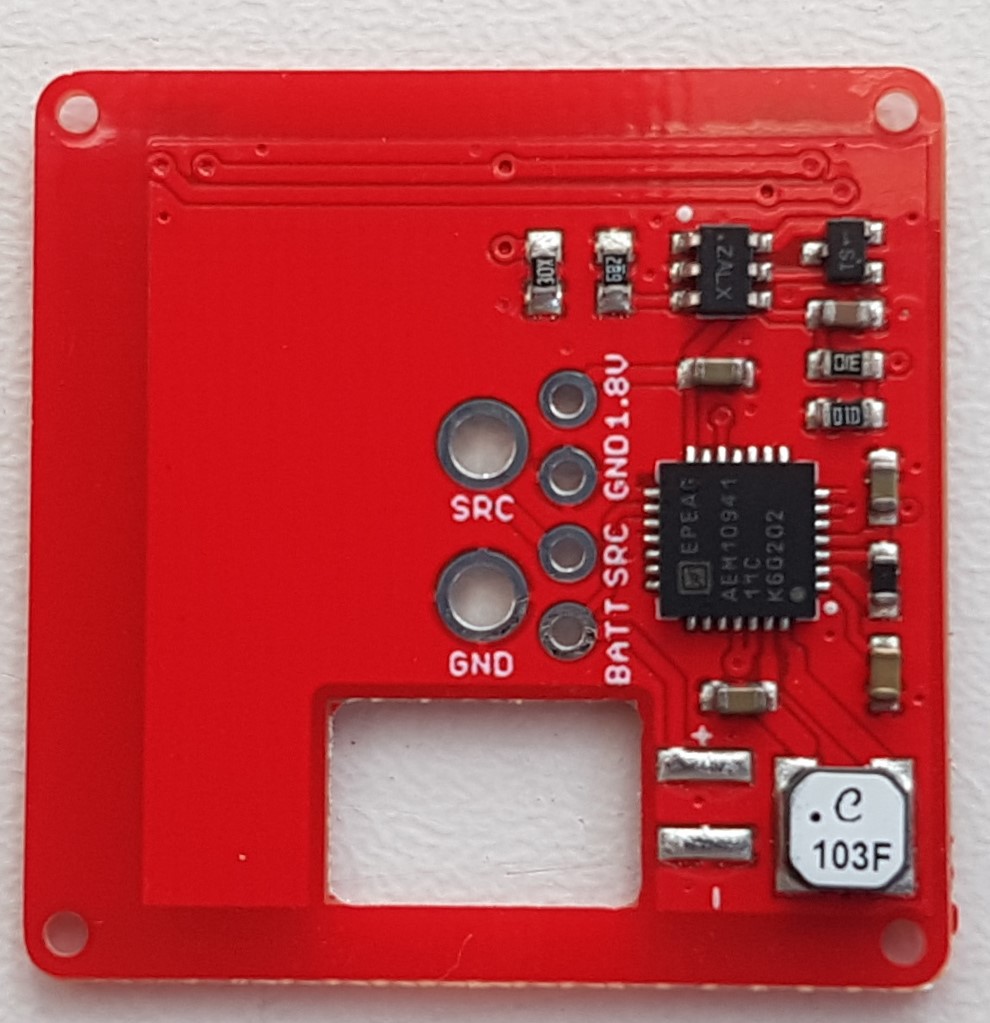
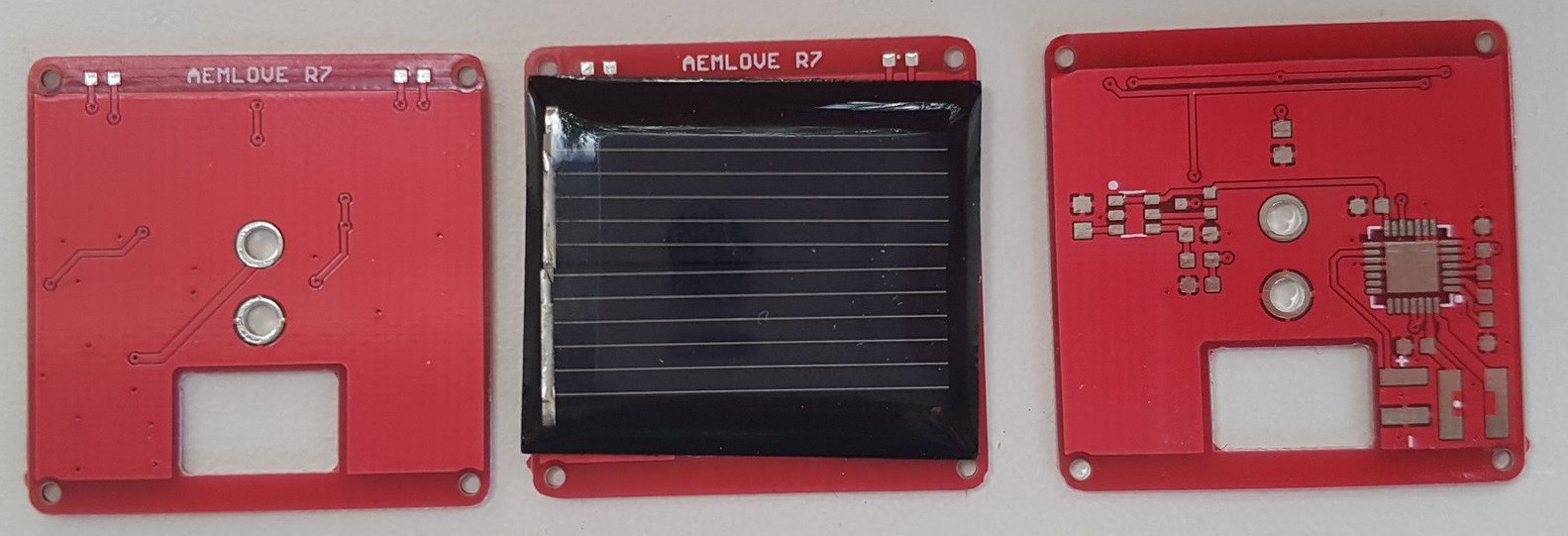
The PCB wihtout any components assembled and a solar panel for reference
I have used the to measure actual LED pulse duration and current from the supercapacitor.
You can see a video of the device actually blinking here. https://twitter.com/jrsikken/status/1137466544555008000
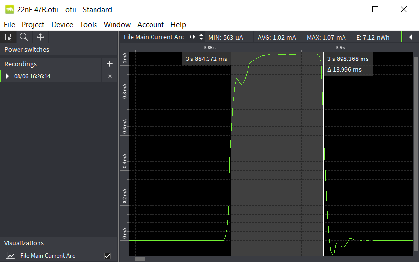
And it shows actual LED was ON for ~14ms. I have experimented a it with the RC values and found shorter pulses were actually perceived as less bright and taking into account tolerances on the capacitor value so I sticked with 14ms.
The average current with the 47 ohms LED series resistor was 6.8uA acording to the Qoitech Otii Arc. I calculated that with a full 1F supercapacitor and 0.5V voltage drop the LED would blink for 20 hours which is far more than the desired 8 hours.
I have changed the series resistor to 20 ohms which gave 1.6mA peak current and 9.6uA average current. Then the LED flashes were nice and bright and the blinking would last 14 hours which is great.
Then I built 4 devices to test actual charge time in full sun and blink duration in the dark.
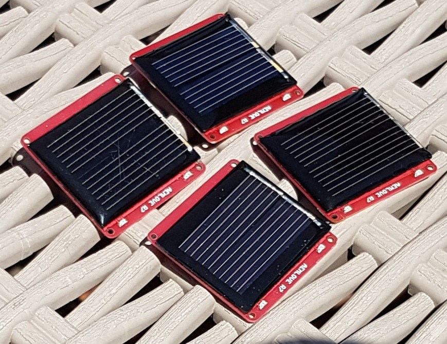
I found at 800W/m2 it takes only 5 minutes to fully charge the super capacitor and they kept blinking in the dark for ~10 hours! This is less than the expected 14 hours. So I need to check what is going on.
What I've learned and can improve:
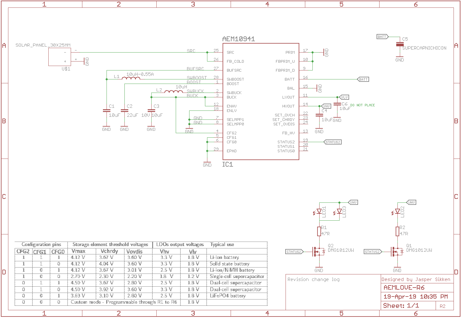
The design changes are:
This is the schematic
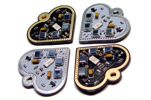
And the assembled PCB looks like this.
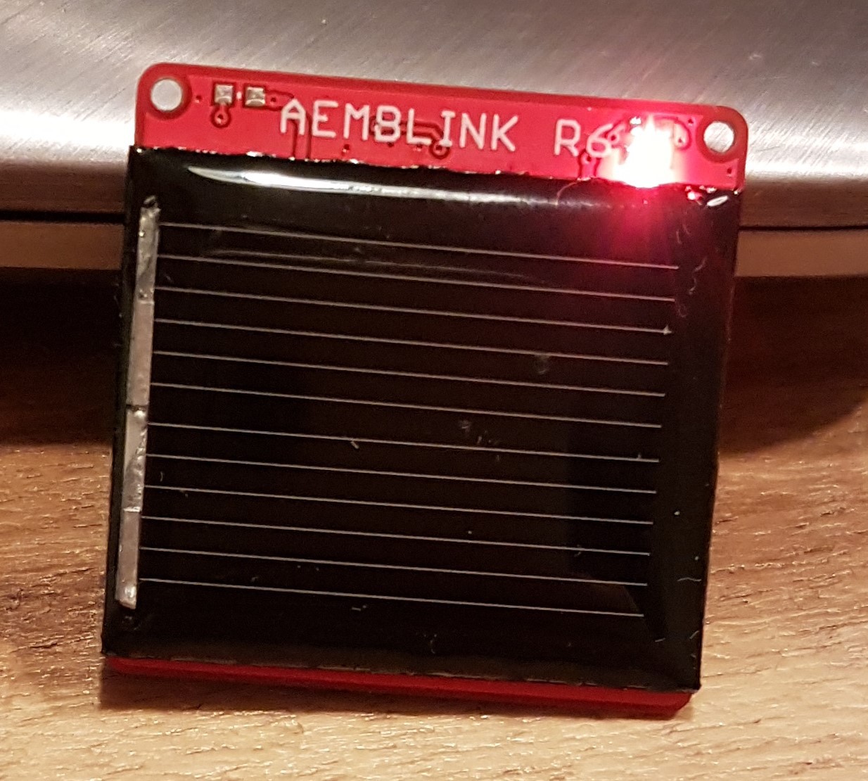
And when it is worn as a necklace is looks like this
I also casted the PCB in two component epoxy resin
And it turned out like this
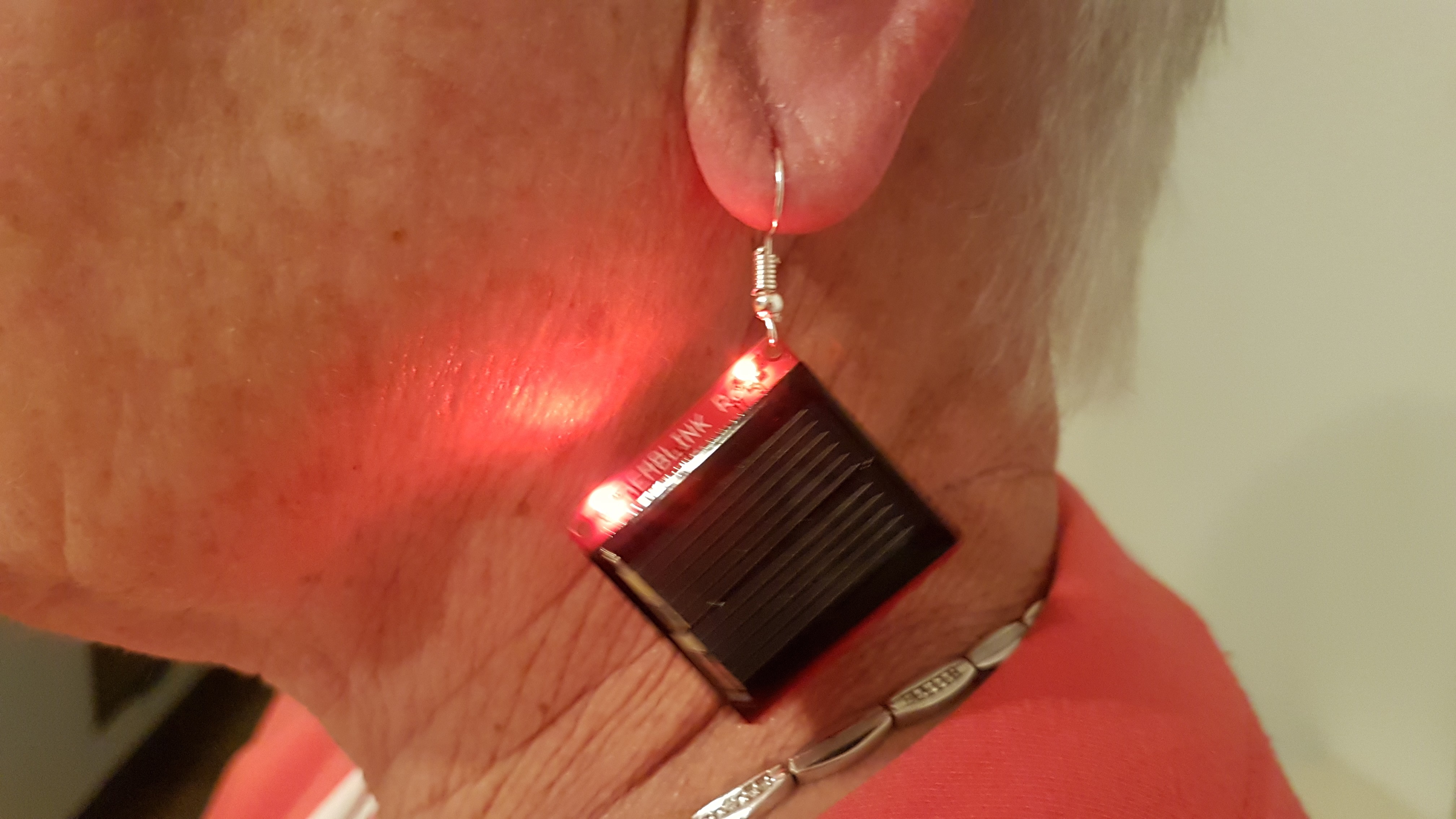
I made my mother wear it as a ear ring
I also casted it into a silicone mold
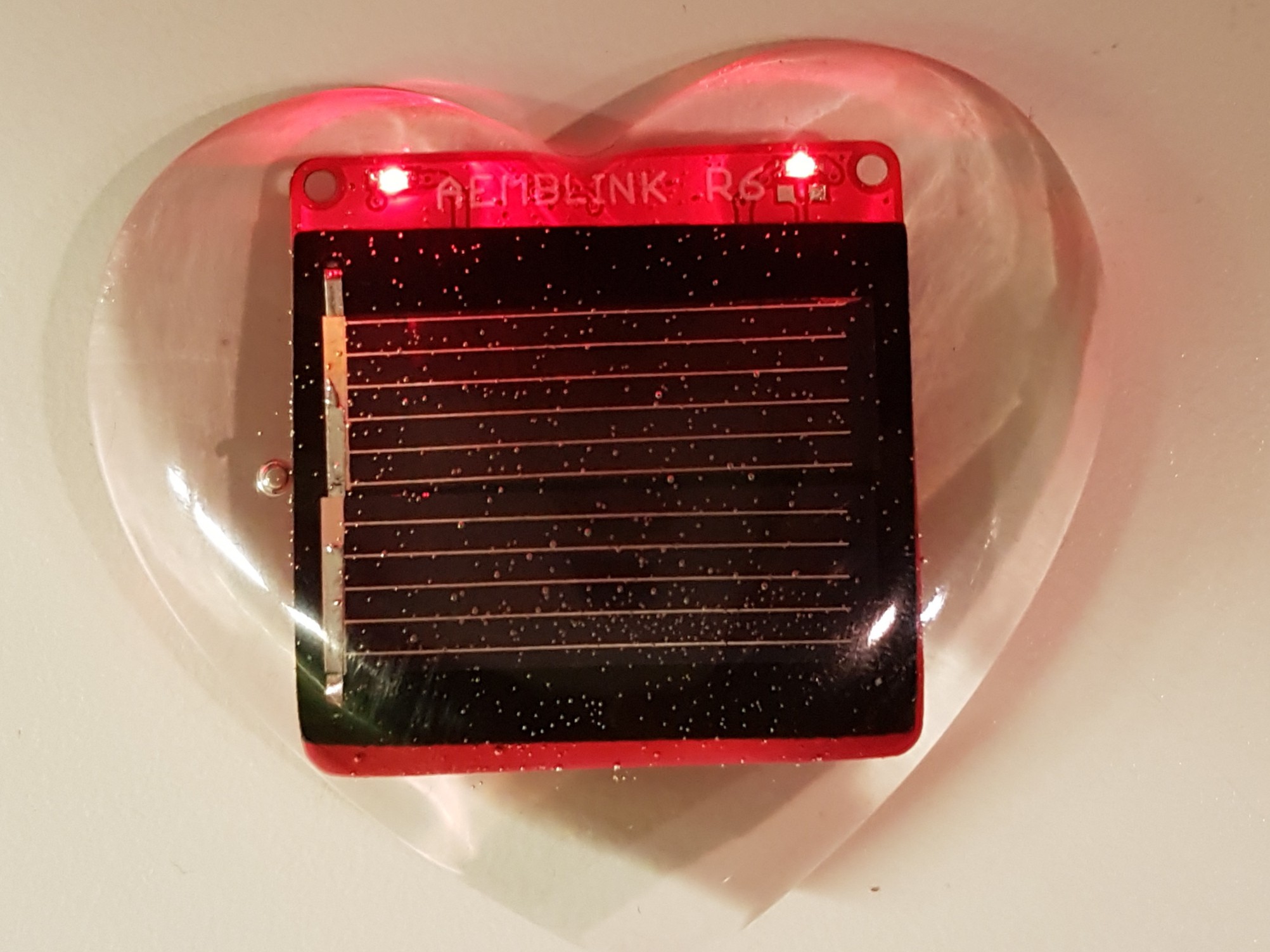
And then it blinks like this
What I've learned from Revision 6
Create an account to leave a comment. Already have an account? Log In.
How did you encase the one in a heart-shape? Cast polyurethane?
Become a member to follow this project and never miss any updates
 Absolutelyautomation
 bobricius

 Open Green Energy
I used a silicone shape from Alirexpress and super clear two compound epoxy resin