The design changes are:
- back to the old red LED
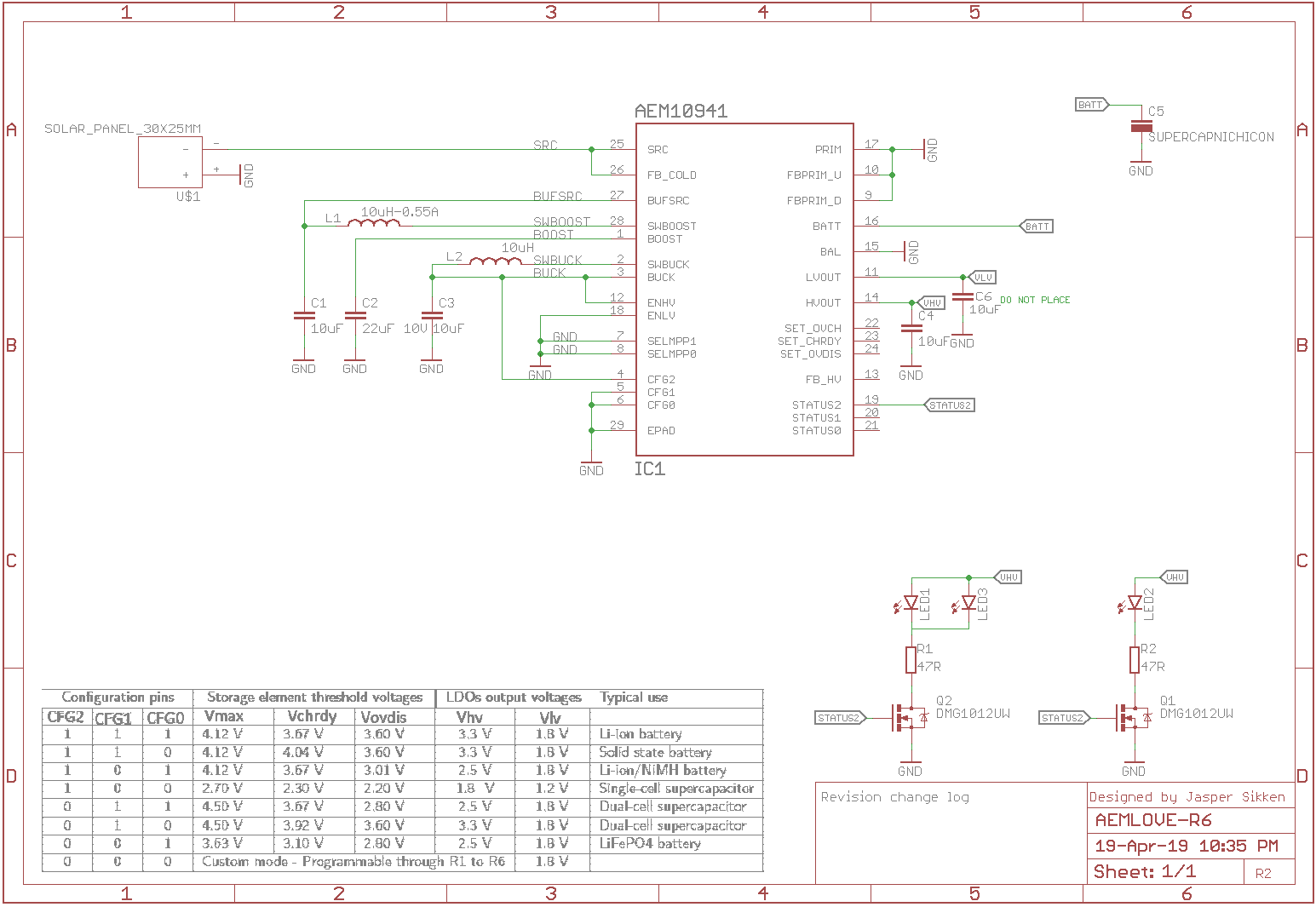
- use only the 1.8V output from the AEM10941
- back to the old blinking circuit that uses the STATUS2 pin from the AEM10941, with 80ms blinks at 5 seconds interval
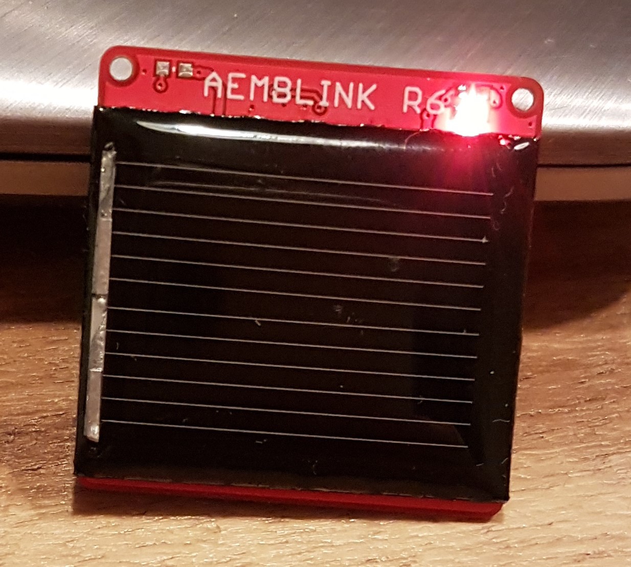
- move the LED to the other side of the PCB, where the solar panel is
- get rid of the USB connector
- use a very thin PCB, so it is not heavy and it is wearable
- experiment with 2 LEDs in parallel, it could improve perception of brightness
- reduce PCB hole for the 1F 2.7V Nichicon supercapacitor
This is the schematic

And the assembled PCB looks like this.

And when it is worn as a necklace is looks like this
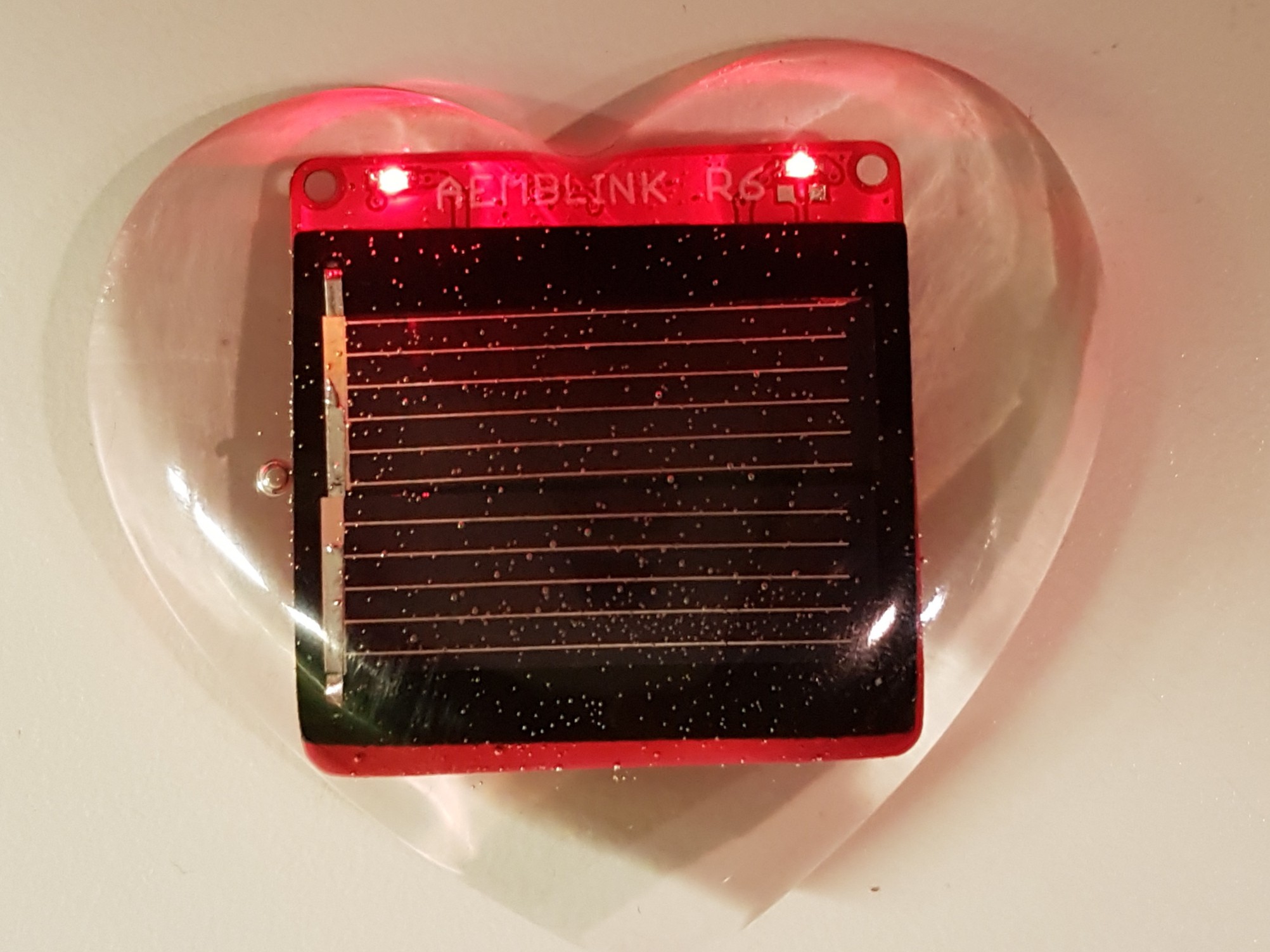
I also casted the PCB in two component epoxy resin
And it turned out like this
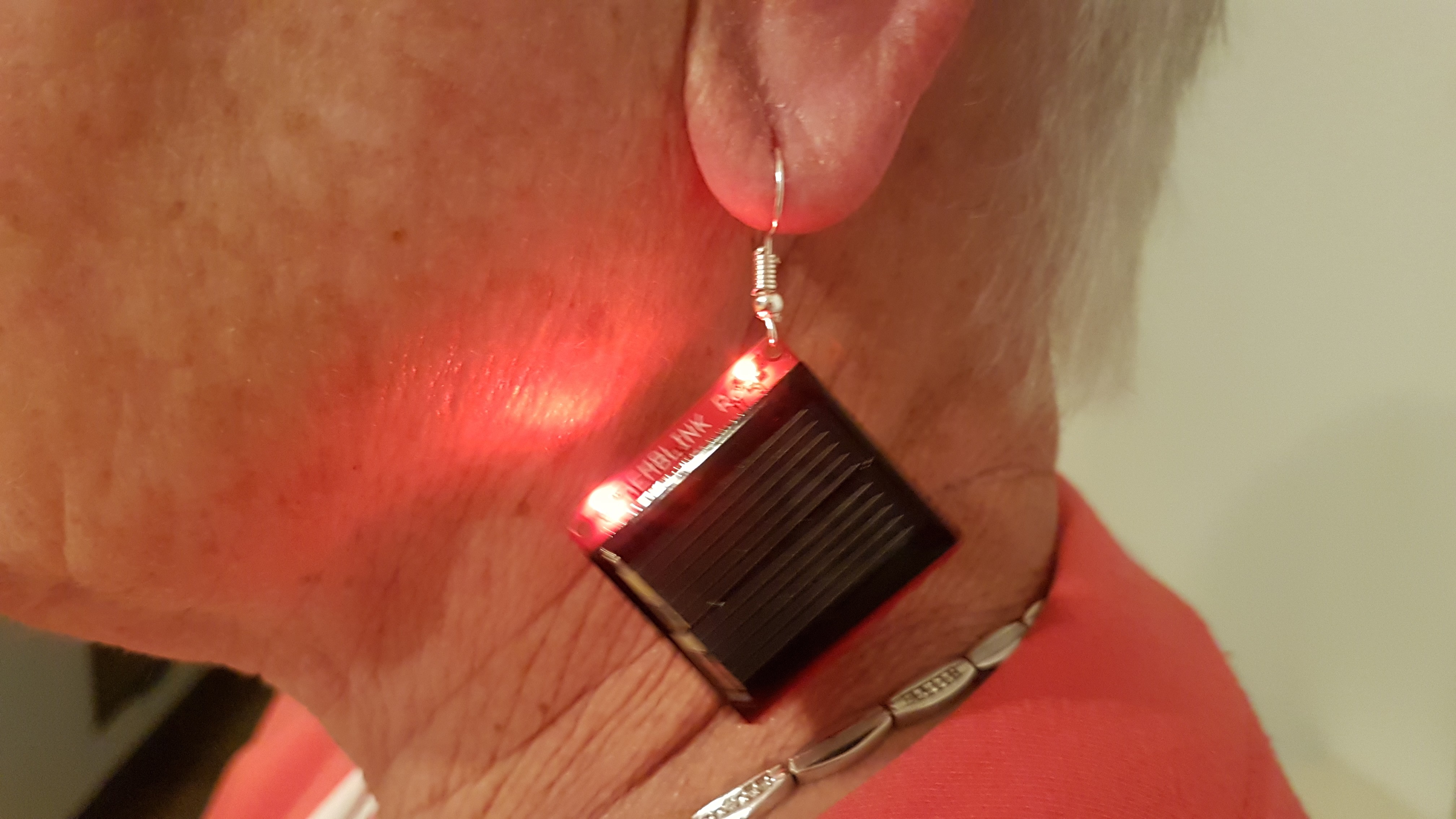
I made my mother wear it as a ear ring

I also casted it into a silicone mold

And then it blinks like this
What I've learned from Revision 6
- I love the LED on other side of the PCB, where the solar panel is
- I love the thin PCB, it makes it light, my mother can wear it as a earring
- It can be worn as a necklace
- it can be a desktop gadget
- two LEDs in parallel doesn't make it so much brighter but it is better visible
 Jasper Sikken
Discussions
Become a Hackaday.io Member
Create an account to leave a comment. Already have an account? Log In.