 Jasper Sikken
In previous AEMLOVE designs I used the STATUS2 output from the AEM10941 to flash a LED which is high for ~80ms every 5 seconds. I think 80ms is actually pretty long and it can be shorter while keeping brightness perception. I learned about 1.5V powered LED flash circuits that have very low average current (~10uA) and wanted to make a similar circuit.
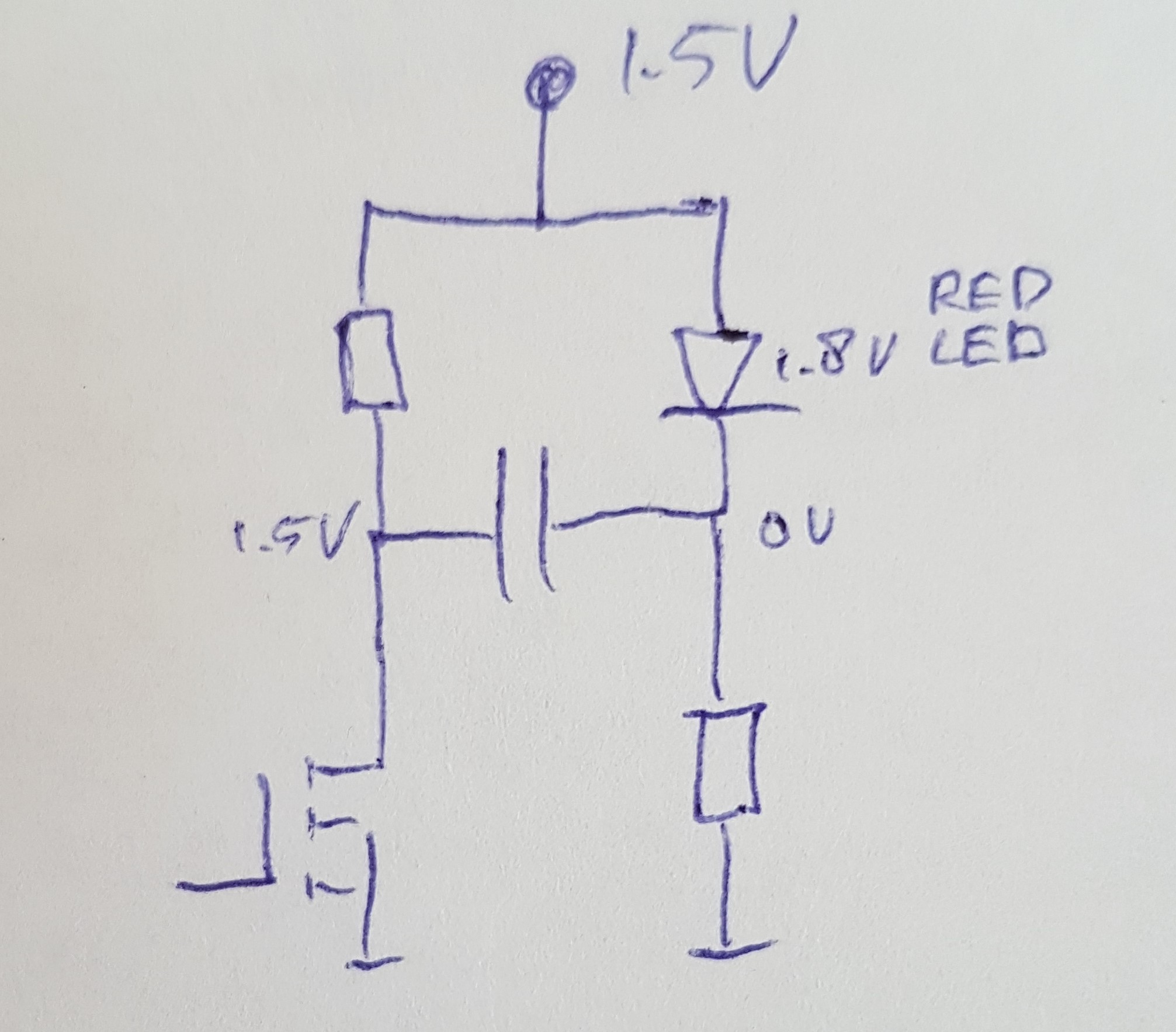
Normally the 1.5V is not enough to light the LED because red led forward voltage is at least 1.7V. So how does it work? First the capacitor is charged to 1.5V through the two resistors. On the left it is 1.5V and on the right 0V. When the mosfet is closed the left side suddenly changes from 1.5V to 0V the right side remains 1.5V lower than than left, and so it is -1.5V Then shortly there is 3V over the LED and it flashes until the capacitor has discharged.
And since the LED can be powered from a very low voltage that is basically doubled it was possible to try out LEDs with higher forward voltage, like a white LED. Since the AEM10941 has two regulated output voltages 1.8V and 1.2V I could design the circuit twice and experiment with it.
I read here that the eye perceives 10ms flashes at full brightness and after that it decays to 50% in 20ms. This means for a 10ms flash you actually perceive 30ms. This could really reduce average current
In revision 5 I made following design changes
- Implement new low power LED flash circuit
- try out white LED
- Move USB connector to lower side of the PCB
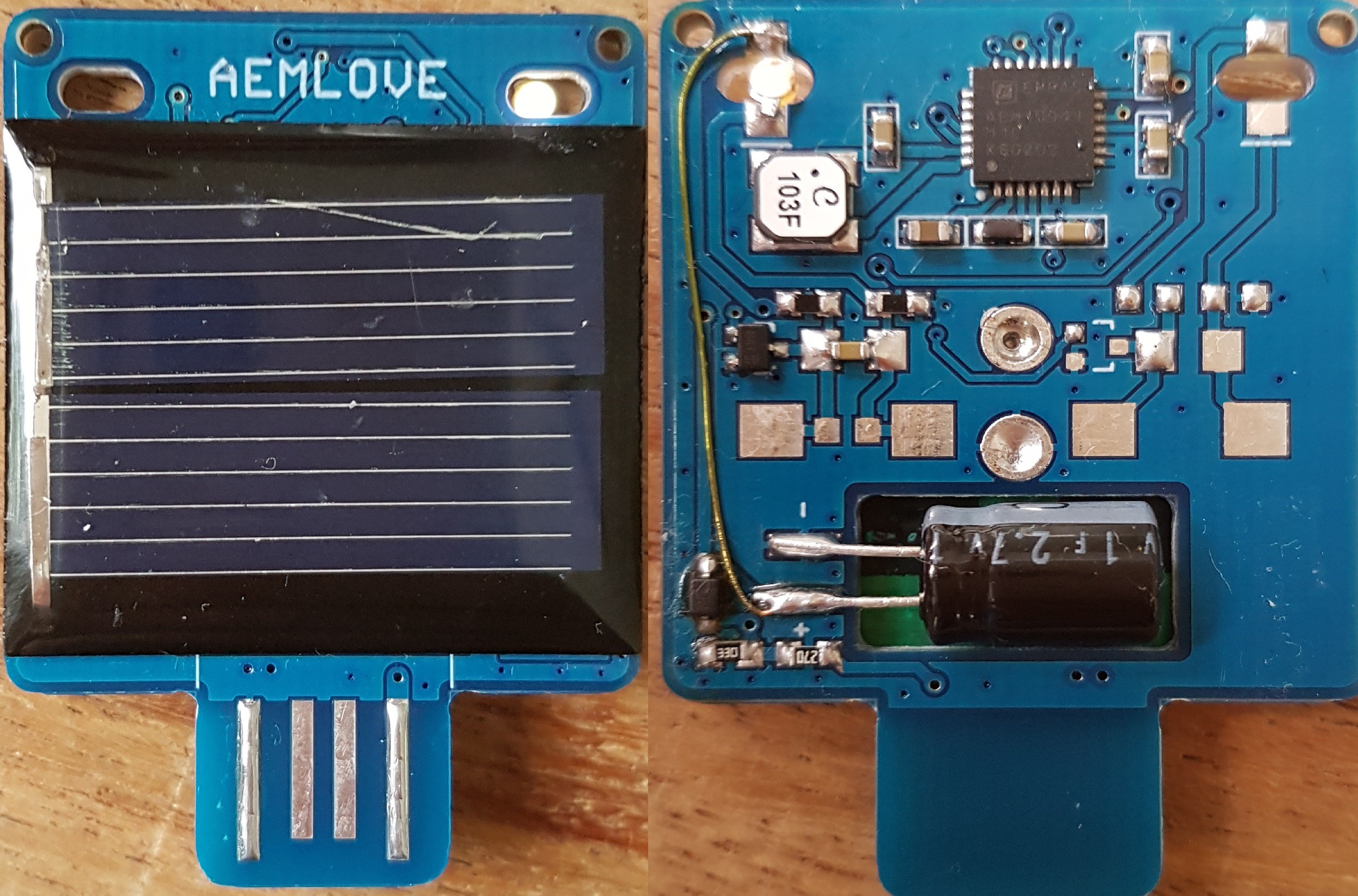
- Use a smaller dimensioned 1F 2.7V supercapacitor Nichicon JUWT1105MCD this has only 6.3mm diameter while previously diameter was 8mm.
- Reduce the hole for the supercapacitor even more
- Use surface mount solder pads for the supercapacitor
- Reduce board size even more
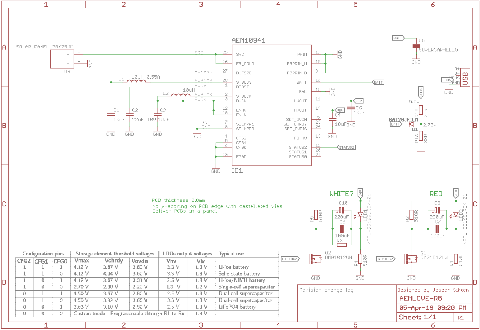
Below is the circuit diagram
What I've learned from Revision 5
- the LED flash is actually not so bright
- the supercapacitor discharged in a few hours while I expected much more
- the hole in the PCB was designed so it could also fit another supercapacitor a 0.5F cheap chinese supercapactors. But I really like this Nichicon super capacitor so the hole can be reduced.
- I also like the SMD solder pads for the supercapacitor
- the USB connector on bottom is definately better than on top
- I didn't like the USB connector anymore, the PCB has to be 2.0mm thick and then it needs the right solder thickness for the USB connector. And still it didn't feel snug. I thought such a connector could actually destroys people laptops.
I was disappointed by the LED brightness and life time. So I made a simulation in LTSpice. Not perfect but it gives me an idea.
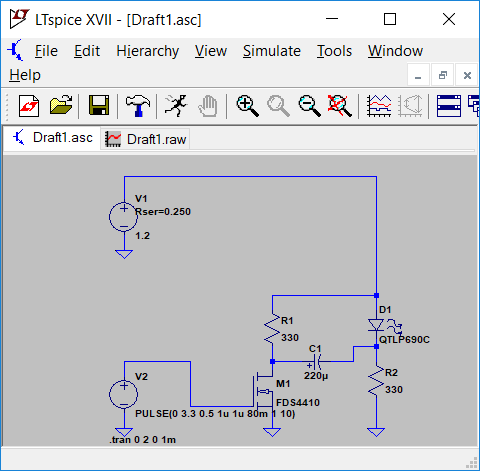
And I found that peak current is actually really high and the duration very low, something like 5ms.
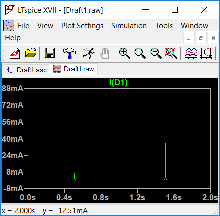
That basically explains why it was not perceived as very bright. In addition it was not low power. So I decided this is not the circuit for me.
Discussions
Become a Hackaday.io Member
Create an account to leave a comment. Already have an account? Log In.