 Jasper Sikken
It's December 2018 when I wanted to design a solar harvesting gadget.
Specifications:
- cheap
- easy to assemble
- uses the E-peas AEM10941 solar harvesting IC
- the IC STATUS2 pin controls the LED ON time (80ms high every 5 seconds)
- LEDs connected through a simple resistor
- on board 0.5V/44mA solar cell KXOB22-12X1L or an external solar panel
- stores it's energy in a through-hole supercapacitor
- can als be charged from USB
- additional LEDs connected through a series capacitor for very short flashes
Since I have 2 children and no time I designed a quick and dirty PCB and ordered from Elecrow. Below is revision 1 schematic.
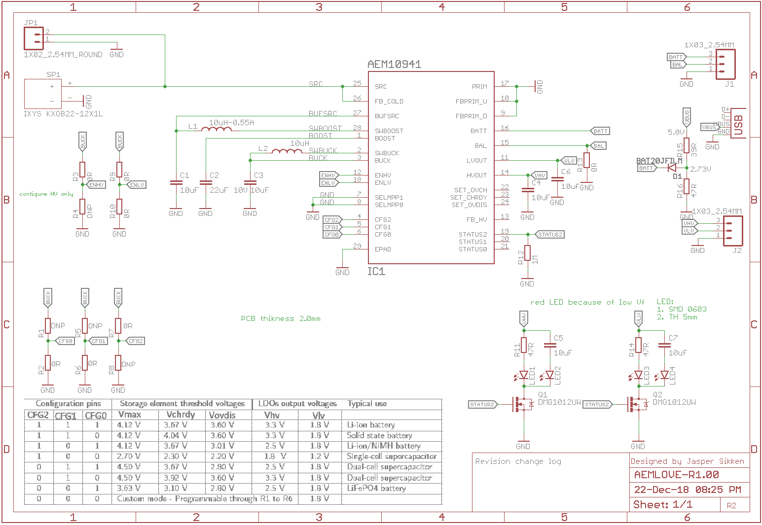
Every 5 seconds the status2 pin goes high when the IC does MPPT evaluation (check solar panel open circuit voltage), I have no idea what applications would need this information but I can use it toe blink a LED with low duty cycle. The LEDs are switched through a DMG1012UW N channel mosfet.
I designed LED on the 1.2V and the 1.8V output of the IC. It was silly to design it on the 1.2V becaise there is no LED that works at such low voltage.
The battery can also be charged from the USB 5V. I used a voltage divider to make a 2.7V voltage for the supercapacitor and a diode to prevent reverse current.
In January 2019 I received the PCB

On the left is the supercpacator A 1F 2,7V through hole supercapacitor from Aliexpress (CXHP2R7105).
On bottom is the solar cell.
On left side is the AEM10941 IC and it's large boost inductor.
The other two large though hole capacitors I did some experimentation with that I won't explain here.
The PCB has 2.0mm thickness. That is not enough for the USB connector so I had to manually add more solder paste.
As you can see she solar cell is surface mount solderable.
What I've learned from revision 1 PCB
- even with 2.0mm PCB thickness and a big blop of solder paste on the USB connector it does not fit snug into the USB port. It feels not right.
- the 0603 size LED from Wurth (150060RS75000) is actually super bright while the programmed current is about 2mA
- after 5 mins charging on USB the LEDs started blinking, but it initially requires some light on the solar panel other wise the IC regulated outputs don't work
- after about 10 mins of USB charging the supercapacitor reaches the programmed voltage of 2.7V
- the LEDs blinks about 14 hours on a full supercapacitor. This is long enough for a wearable.
- the voltage divider on the 5V gets untouchable hot
- a single 0.5V/44mA solar panel does not charge the 1F super capacitor quickly, it took about 10-20 mins in outdoor light before the LED started blinking
- the series capacitor make the LED blink only once, so that does not work.
PCB revision 2 you will find in the next project log.
Discussions
Become a Hackaday.io Member
Create an account to leave a comment. Already have an account? Log In.
You are welcome. I am not sure I understand your question. Ofcourse you can put two supercapacitors in series, they need some kind of balance circuit so they each have 1/2 of the voltage. Normally the test of the circuit connect to the most positive terminal
Are you sure? yes | no
Hi @Jasper Sikken thanks for the helpful feedback on rev 1. I was planning on using a 2.0mm PCB for a usb connector for V1.1 of #Yapolamp but will review that plan now.
I have been experimenting with a constant current charging circuit on two supercapacitors in series. Could you implement something similar but only connect the rest of the circuit to the midpoint between the capacitors?
Are you sure? yes | no