 agp.cooper
An Offset Laser Engraver
Mathematically it is just a polar adjustment (i.e. a radius from the right elbow with a rotation. For my design:
- LL=207.020 mm
- LA=-4.671 degrees (i.e. on the right)
Mathematical Instability
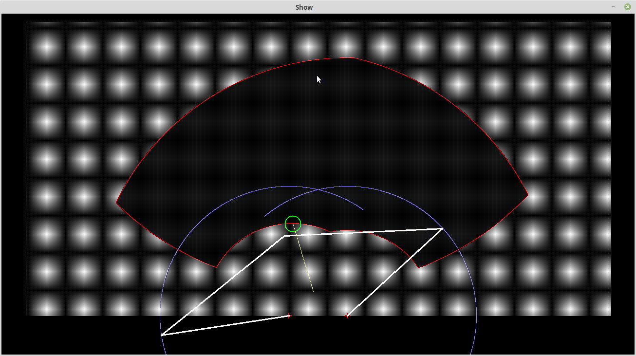
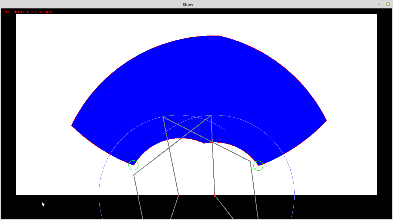
Before the transformation:
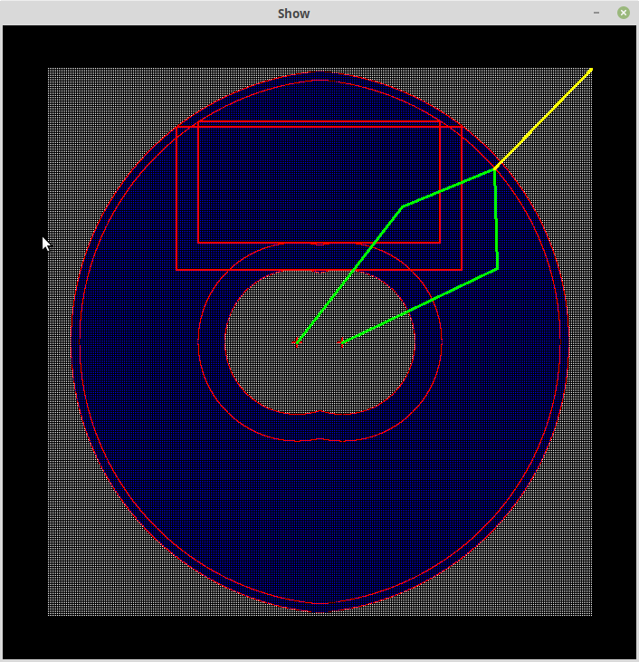
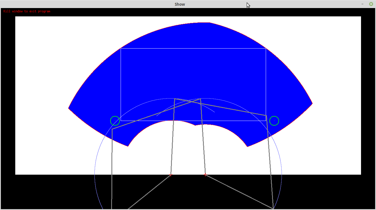
After the transformation:
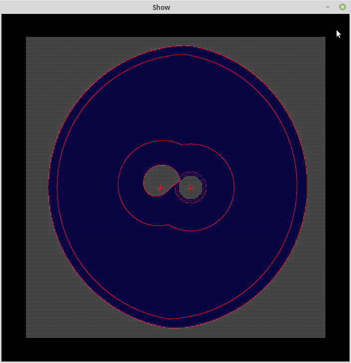
Note the mathematical instability around the right arm pivot. It is due attempts to solve near zero angles with the Cosine Rule. It is not an issue as i is not inside the design operational envelop.
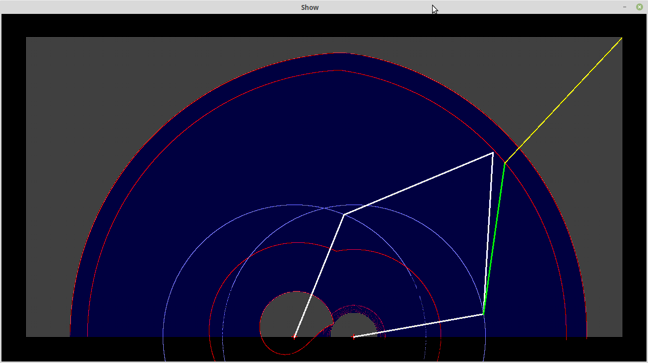
Other Transformation Problems
Here there are some transformations into the minus Y area:
If I lift the minimum Y to ~36 then "minus Y area" transformation problems are gone (other than the bottom right "tick"):
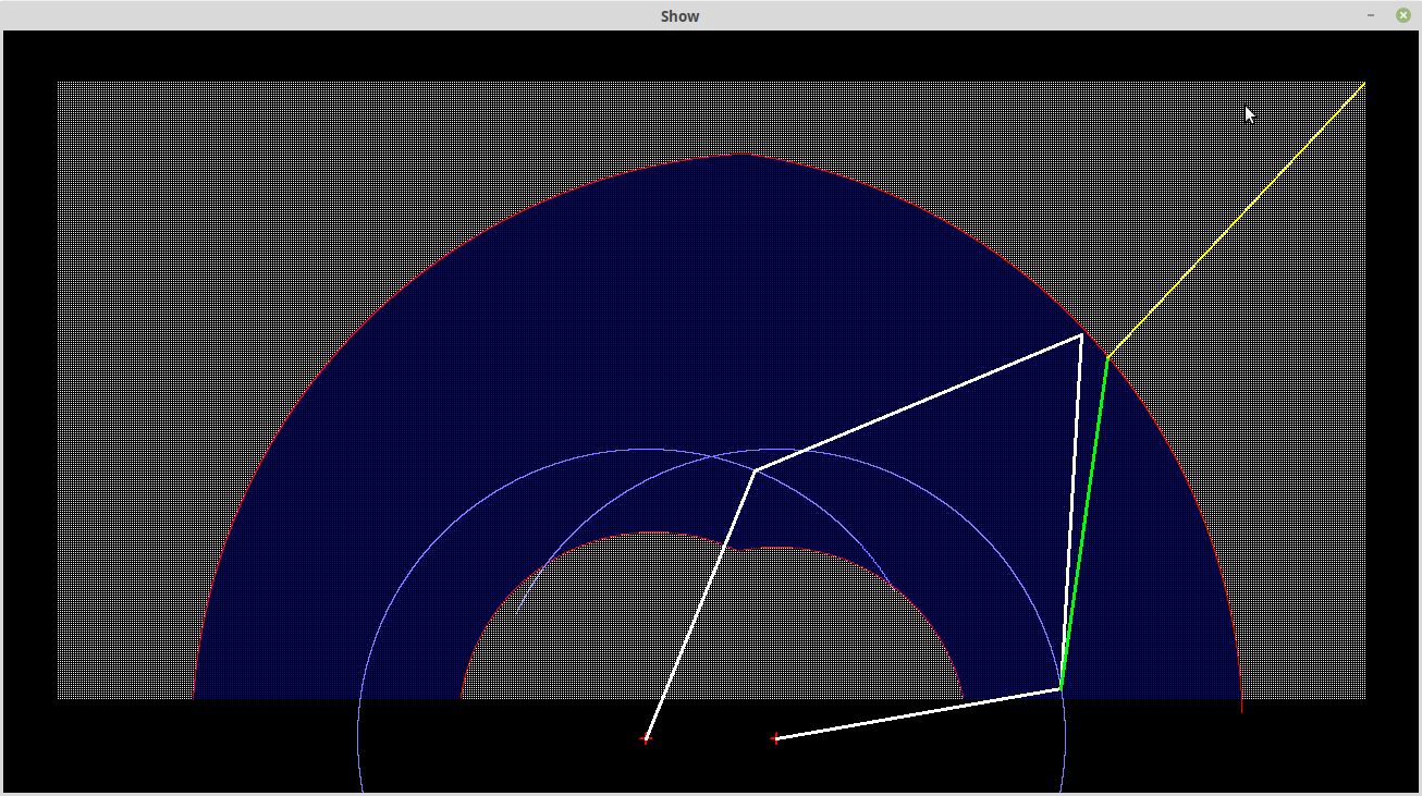
So now I have a stable mathematical model (if restricted to the working area above Y=~36).
Update
I was not that satisfied with the above solution. This solution looks better:
I suppose it is time to look at the base board. Okay here is the base board:
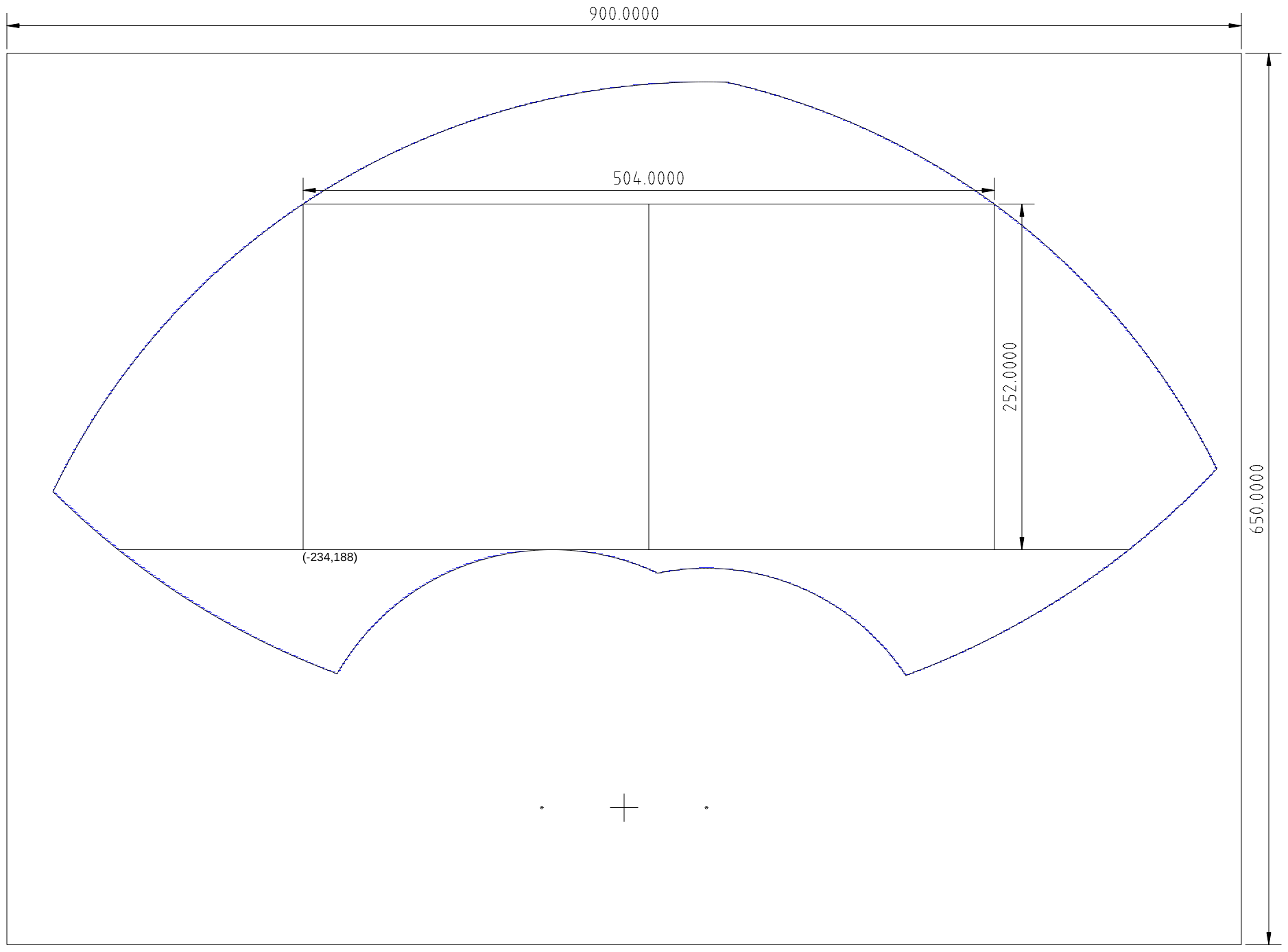
Too hard to solve the equations analytically so I just exported the "edge" points and fitted by eye the arcs. Then I fitted the largest possible 2:1 rectangle.
Small Board Format
Rather than use the full board, I am now looking at a small board format. The top edge of the board is the bottom edge of the work area:
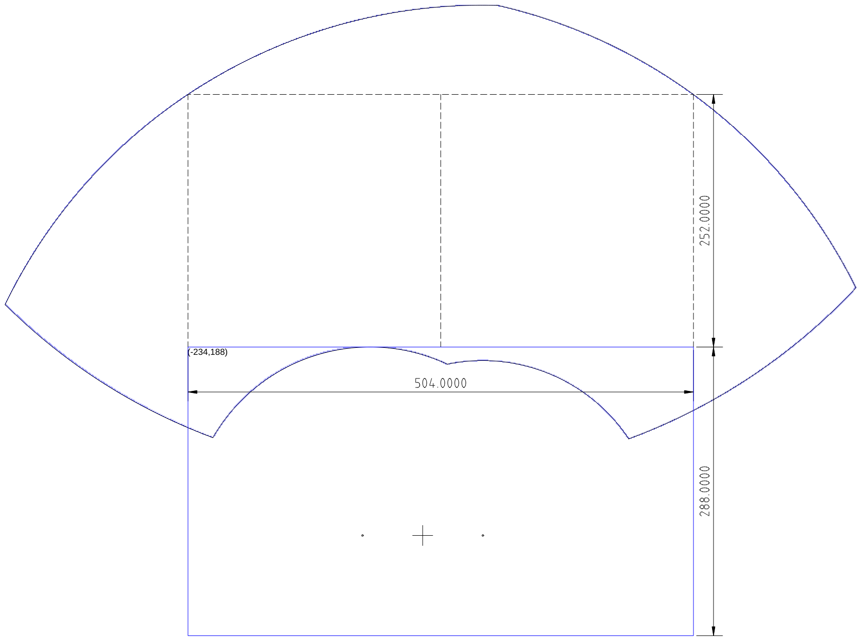
The small board allow 100mm behind the arm pivots.
Homing
The last SCARA I built used micro-switches to find the home position. It was not effective just to drive the arms into a stop position, as the SCARA was direct drive and used micro-stepping. It would just "bounce" off the stop position depending on the micro-step position. This time, it could be more effective if the stepper motor pulley is loosened and re-tightened, then the home position is a power-on detent position.
Stepper Motor Mounts
Time to work on the stepper motor mounts.
Added the work so far to the small board:
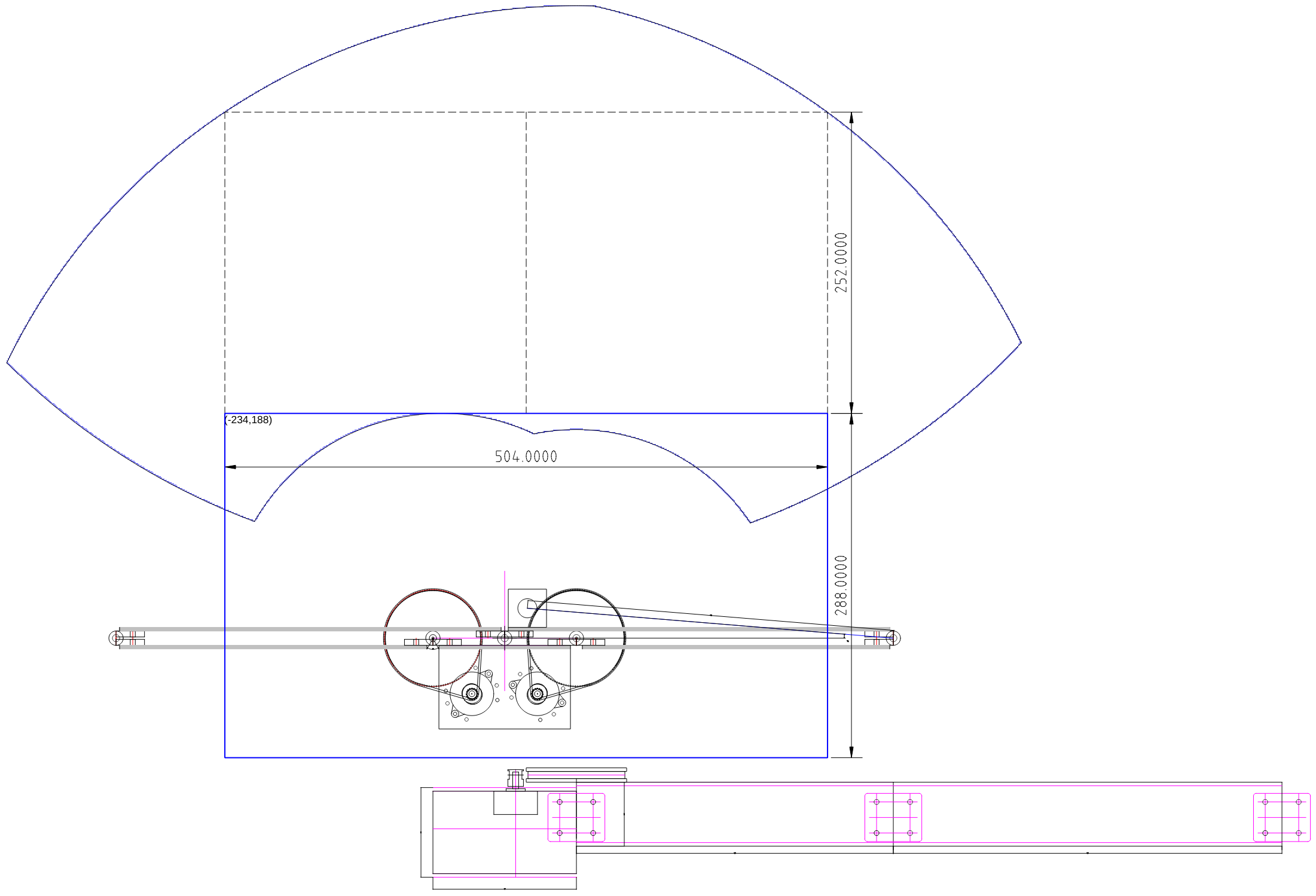
The design is far from done but it looking okay (note, the arms do not show any stiffening flanges).
I have to check how far the near arms need to fold back:
Yep, pretty extreme, the left arm: 251.60 (i.e. 71.60) degrees and the right arm: -52.25 (i.e. 52.11) degrees. I have only made an allowance of 58.11 degrees.
Actually, if I constrain the SCARA to the potential work area above Y=188.0 mm then the there is no problem (i.e. UL=38.02 degrees and UR=26.67 degrees):
Alan
Discussions
Become a Hackaday.io Member
Create an account to leave a comment. Already have an account? Log In.