Input signal processing
Since the delayline uses ultrasonic soundwaves in the range of 4.33 +- 1 MHz to propagate a signal, we cannot use it to transfer a DC signal. Thus, the signal needs to be modulated somehow. A simple Modulation technique is Amplitude Modulation, as it can be implemented by a simple and-gate that takes the carrier frequency and the payload signal as inputs. I used a 74hc02 nor-gate and inverted input signals:

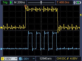
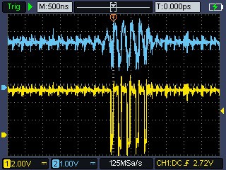
The following picture shows the input of the modulation stage in yellow and the resulting modulated signal in blue.
The delayline can be directly driven by the and-gates output in series with a 100-200 Ohm Resistor. When driven by a 5 Volt Signal, the output of the delayline gives a signal that swings from -0.5 V to 0.5 V.
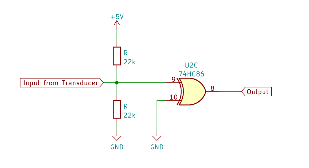
To amplify and reshape to digital, it is connected to the input of a logic-gate that is also biased to 2.5 V by a voltage divider. I had achieved good results using a voltage divider made from two 22k-resistors. As the amplifier-gate I chose a 74hc86 xor-gate as a non-inverting buffer:
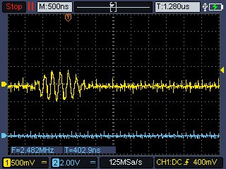
After some playing on the breadboard, i soldered four delaylines and twos 74HC86N to a piece of stripboard. The result signal has an even higher Amplitude. Here is a picture of the input and output of the amplification stage at the end of the delayline. (Note that the output is high when there is no signal, even if the delayline was fed an inverted signal)
After testing and playing around for a bit, the four delaylines where wired in series to create 256 microsecond delayline.
Bit selection circuit
To read or write bits to the delayline, i nedded a device that counts the bits in the delayline and creates a signal when the desired bit is passing through the output stage of the delayline. I uses a 74hc4040 counter-chip that is fed by the carrier clock signal. Output B of the counter is used as the bitclock, giving four impulses of the carrier per bit. The following 8 outputs (C-H) are fed to two digital comparators made up from some xor- and and- gates that get the values to compare against from two 74hc595 shift-registers which are connected to a microcontroller via spi. One of the comparators outputs is connected to the reset-pin of the counter, giving control over the period, the other comparator will be the bit-select signal, which will be high for the time the selected bit is coming into the modulation stage.
Output signal processing
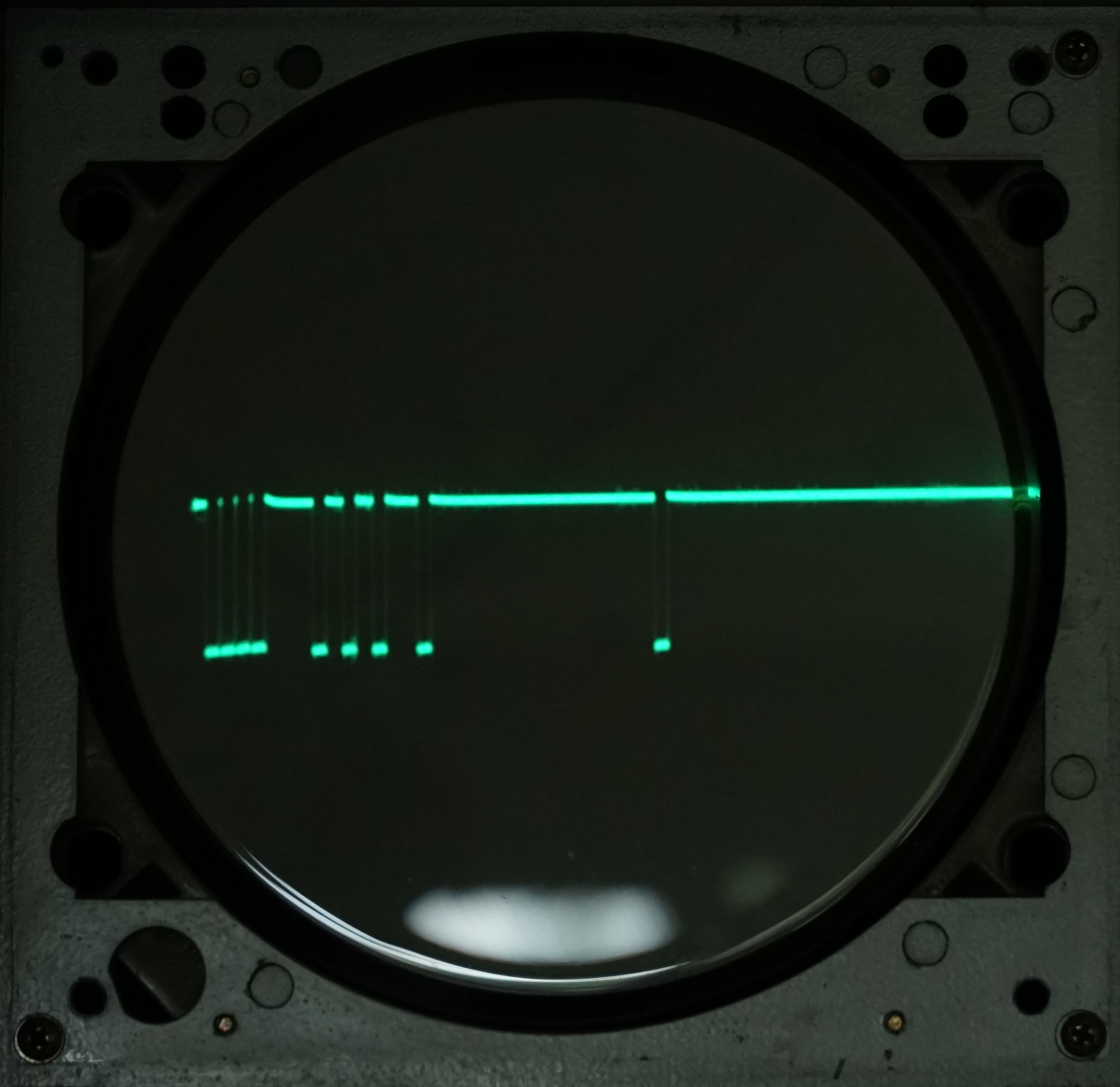
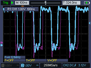
After passing through 4 delaylines and their amplification stages, the signal still shows 4 pulses for a single bit, but the pulses are not as precise as the original signal. Also I need a single pulse for a single bit instead of four.
Here is the output of the first stage laid over with the original input signal:
Second stage:
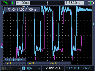
Stage three:
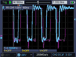
And the final output:

Notice how especially the last pulse gets shorter after every stage. If that signal was fed back to the delayline it would fade out after a couple of circulations. So it needs to be demodulated, retimed, and then modulated again.
My first idea was to use an analog lowpass filter but i was not able to get reliable results. Instead i connected the output of the delayline to the set-input of a 74hc74 flipflop. The set-pin of that chip is low-active so it came in handy that the output of the delayline is inverted. Each time the delayline output goes low, it will set the flipflop. The reset of the flipflop is pulled high, the data input is pulled low, and the clock input is connected to the bitclock that runs at 1/4 of the carrier. That way the flipflop is set to off on every positive edge of the bitclock, and switches on if there is at least one pulse on the output of the delayline in between two rising edges of the bitclock signal.

Here is a picture of the circuits input- and outputsignals:

The purple line shows the outputsignal of the delayline-module, the yellow line represents the bitclock signal, and the blue line shows the resulting...
Read more »
 zpekic
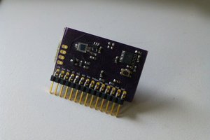
 doctek
 Craig
Craig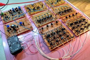
 matseng