 HackersHub
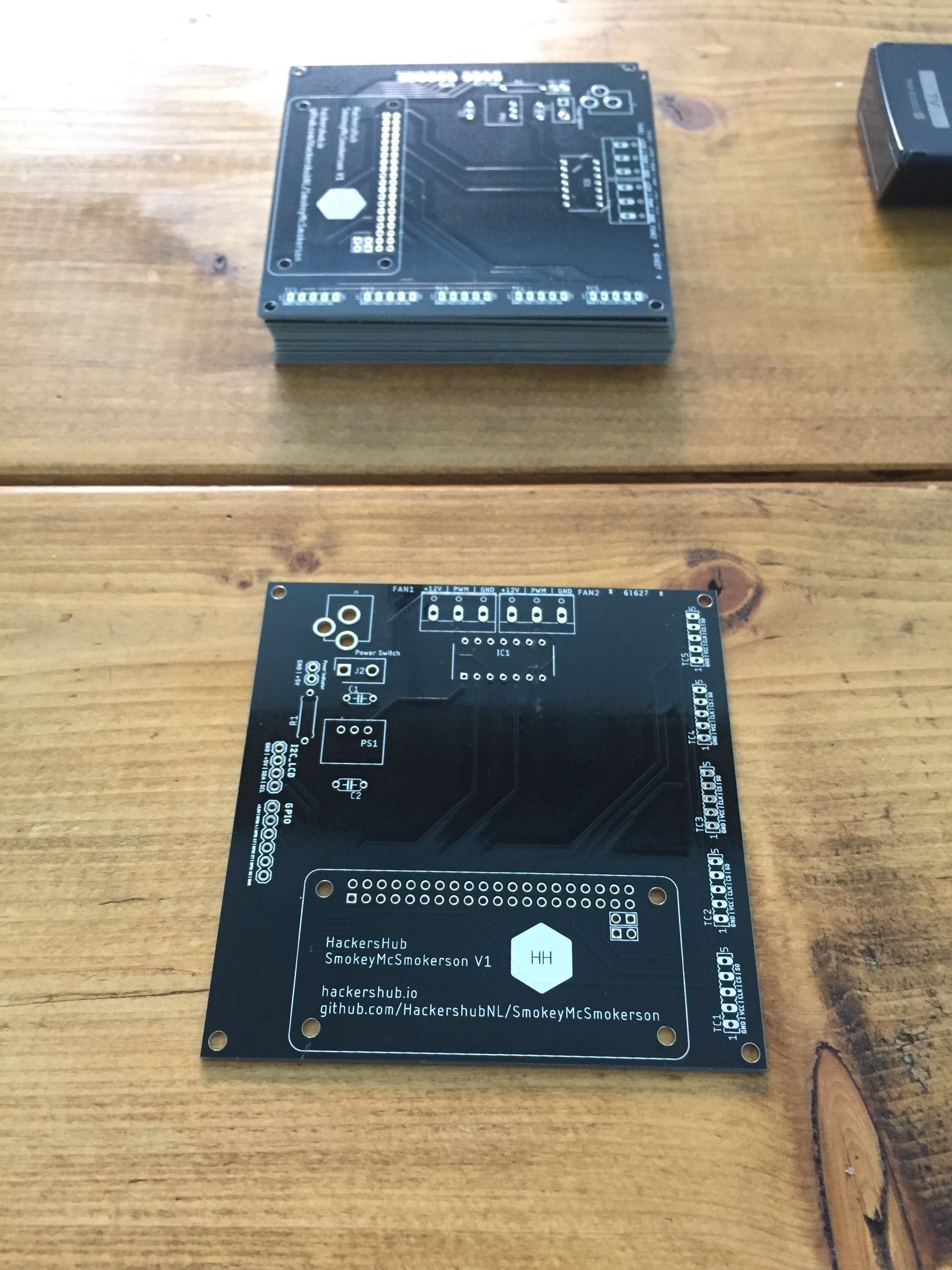
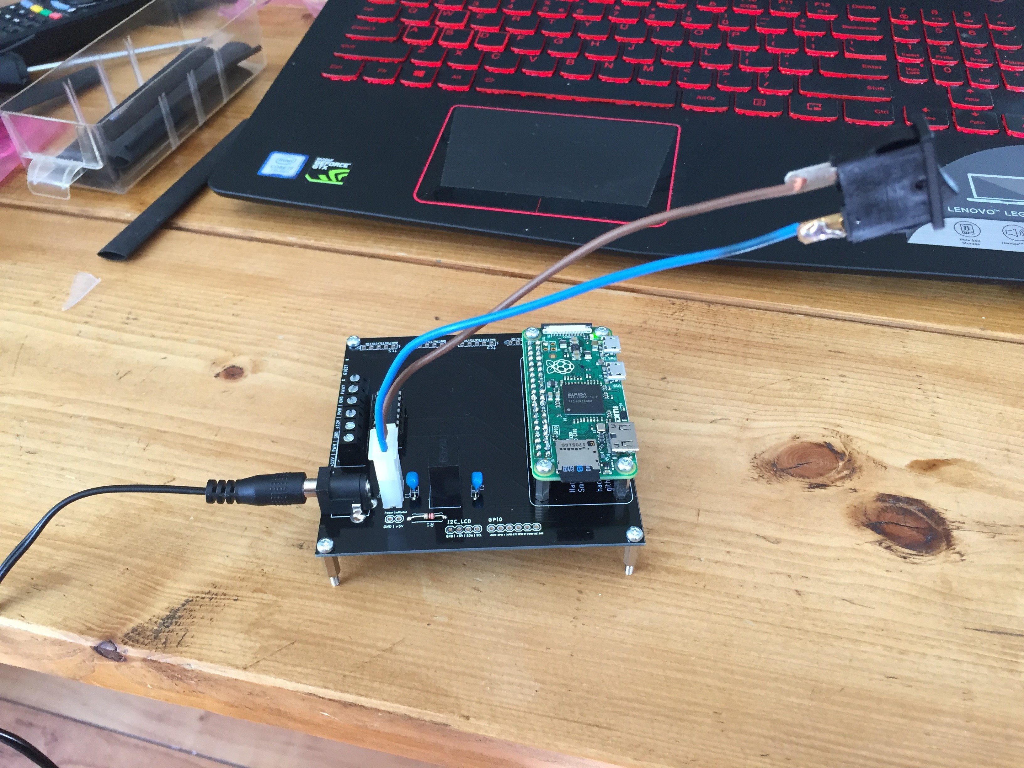
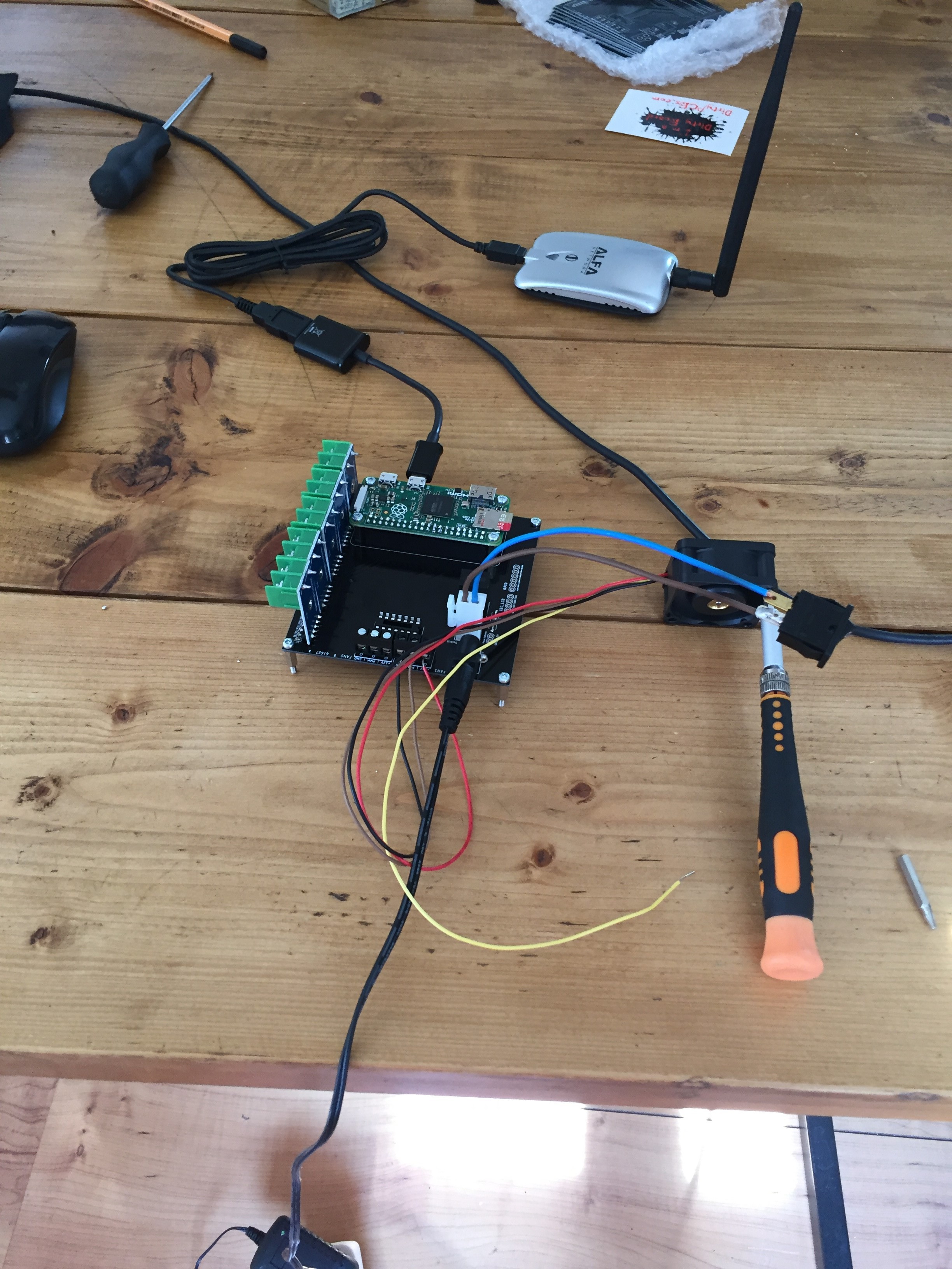
After a 3 month waiting time the boards finally arrived from Dirty PCBs.
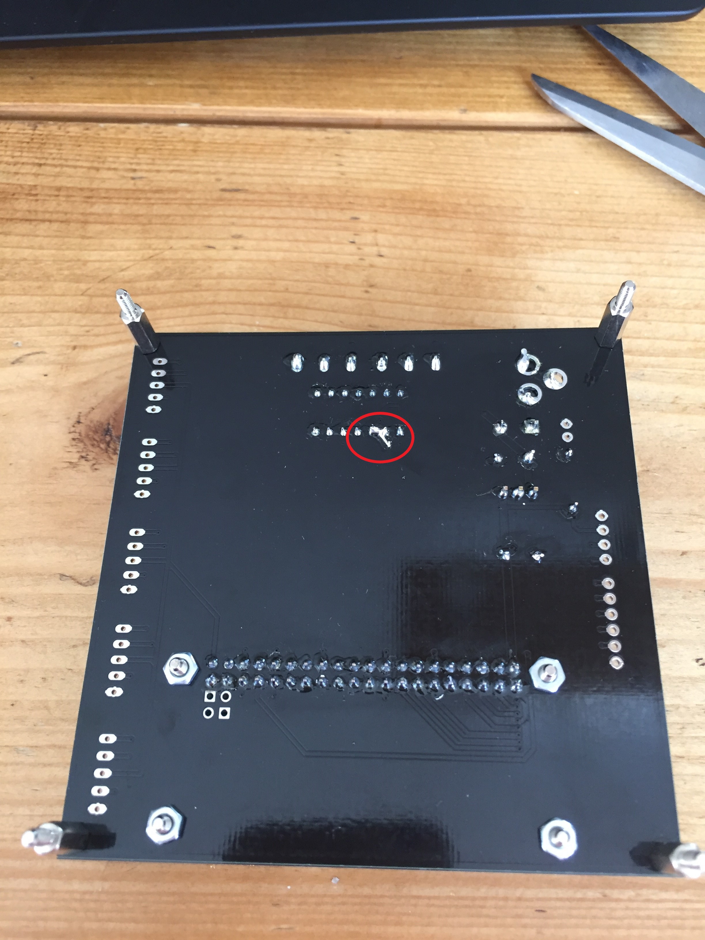
With the first board put together in issue come up where the PWM boost circuit didn't work properly but luckily the fan works just fine with a 3.3V signal so for this version the boost chip will be bypassed aka a hack job :)
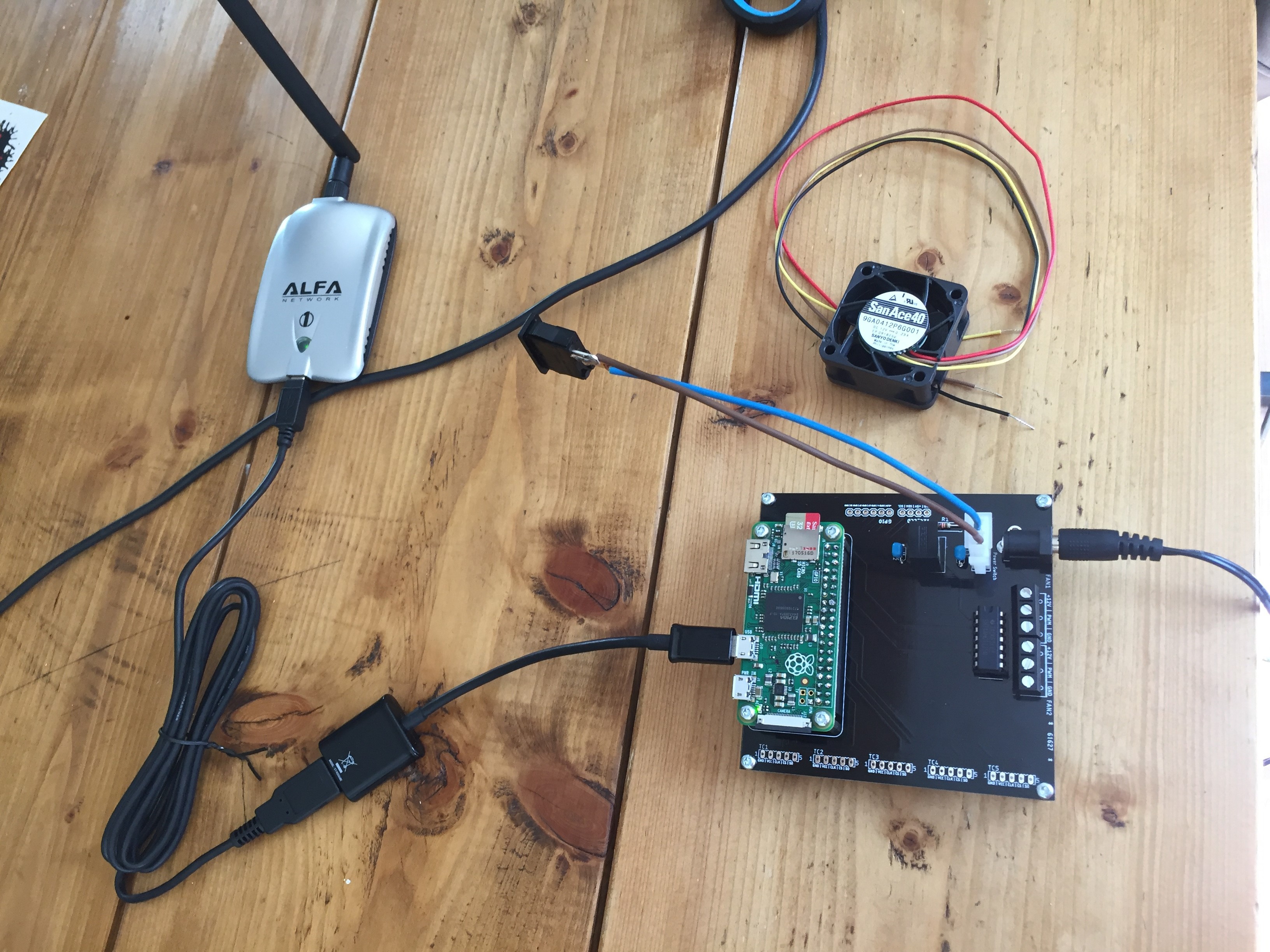
I have updated the code so everything works and the next step is mounting it to the barrel and testing it out. More pics below.
Discussions
Become a Hackaday.io Member
Create an account to leave a comment. Already have an account? Log In.