-
Charging and discharging test
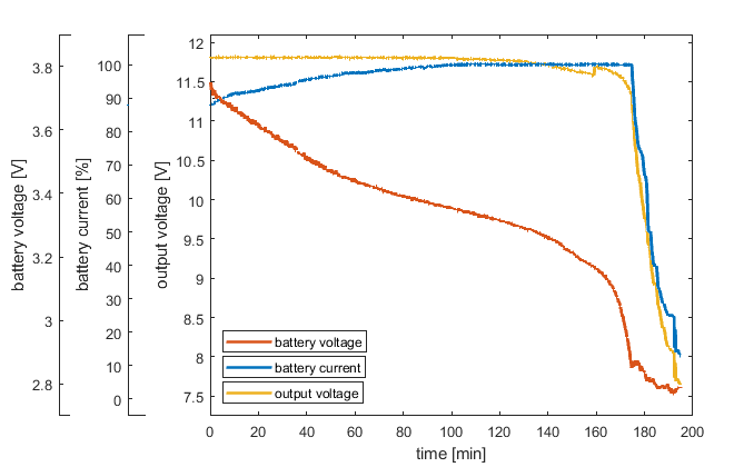
05/30/2019 at 15:03 • 0 commentsHere are the graphs of first charging and discharging runs. The battery was loaded with 500mA current sink during discharge and supplied from 13V (1Alimit) voltage source during charging.
![]()
During discharge the converter passes trough three modes. First is the constant output voltage. As the battery voltage drops, the battery current rises to the maximum limit. At that point the converter enters into maximum current regulation and the output voltage starts to fall. As the battery voltage reaches minimal value of 2.8V the maximum current starts to be lowered to avoid over discharge at that point the output voltage falls even lower and the test is stopped when the current falls below 10% of maximum value.![]()
During charging similar three modes of operation are visible. The first one is the short period of maximum battery current limit. Then as the battery require more charging power (battery voltage rises and current stays the same) the power supply input start to fall under the input voltage limit (12.1V) and the converter start to lower charging current not to over-load the source. As the battery starts to reach maximal voltage (4.2) the charging current starts to be lowered and the power supply can recover back to initial 13V. -
First start-up
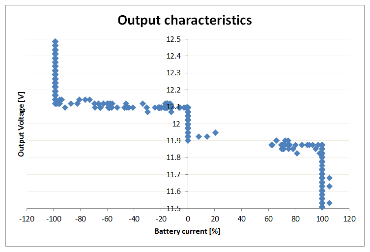
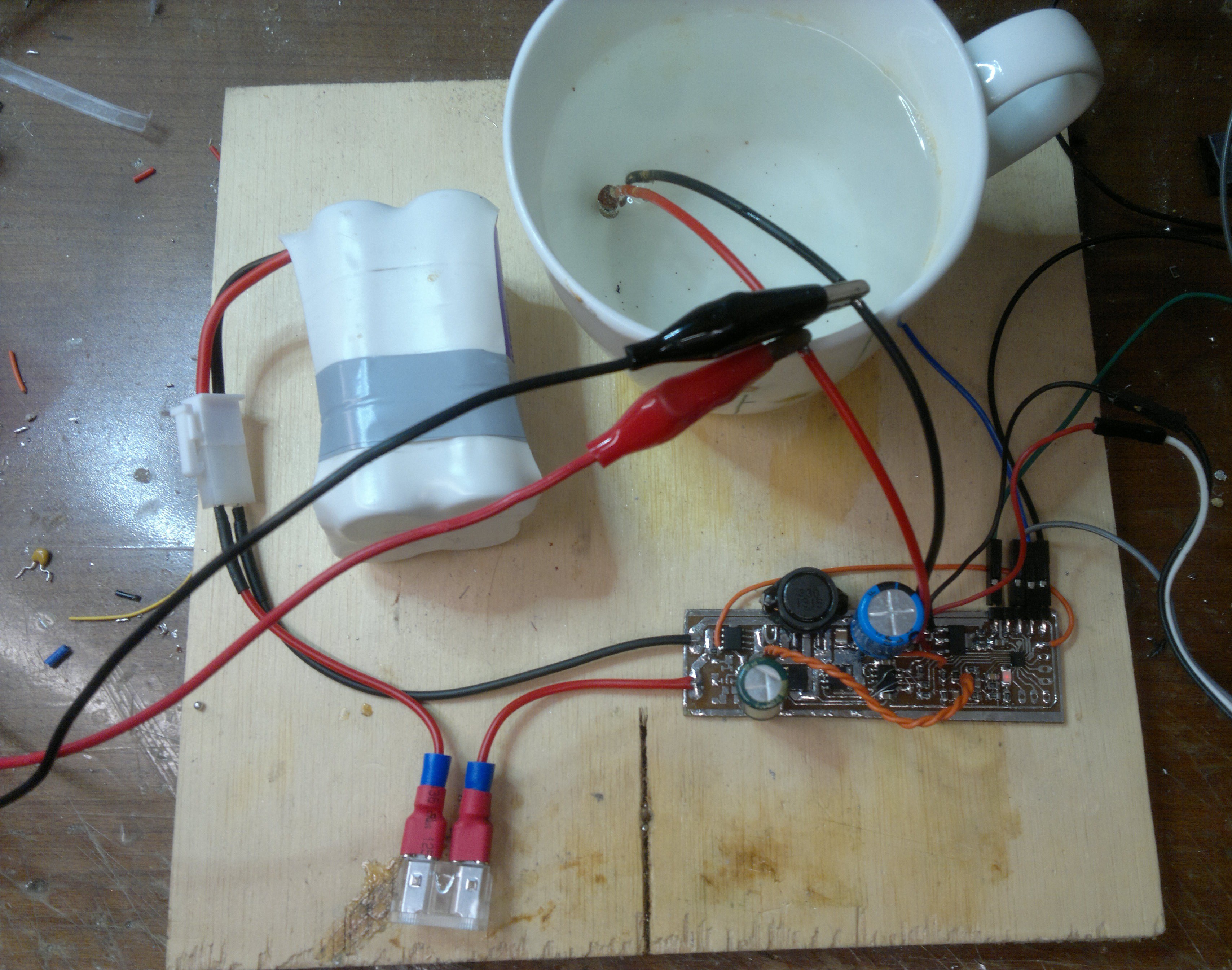
05/30/2019 at 14:46 • 0 commentsI connected the converter to 4 Li-ion 18650 cells and its output to load resistor parallel with regulated power supply. This way a could change the amount of load put to converter both sourcing and sinking current. To keep the microcontroller "independent" I powered it and mosfet driver from 5V USB-port through the rs-232 converter to which the microcontroller was reporting internal state. Bellow is the is the plot of self-reported output voltage vs battery current. The two modes of operation can be seen in which converter sinks current when the voltage is above 12.1V and sources current when voltage is bellow 11.9V. At certain level the converter goes into maximum current protection and the converter switches to constant (battery) current mode.
![]()
The test setup:![]()
-
Schematic and PCB
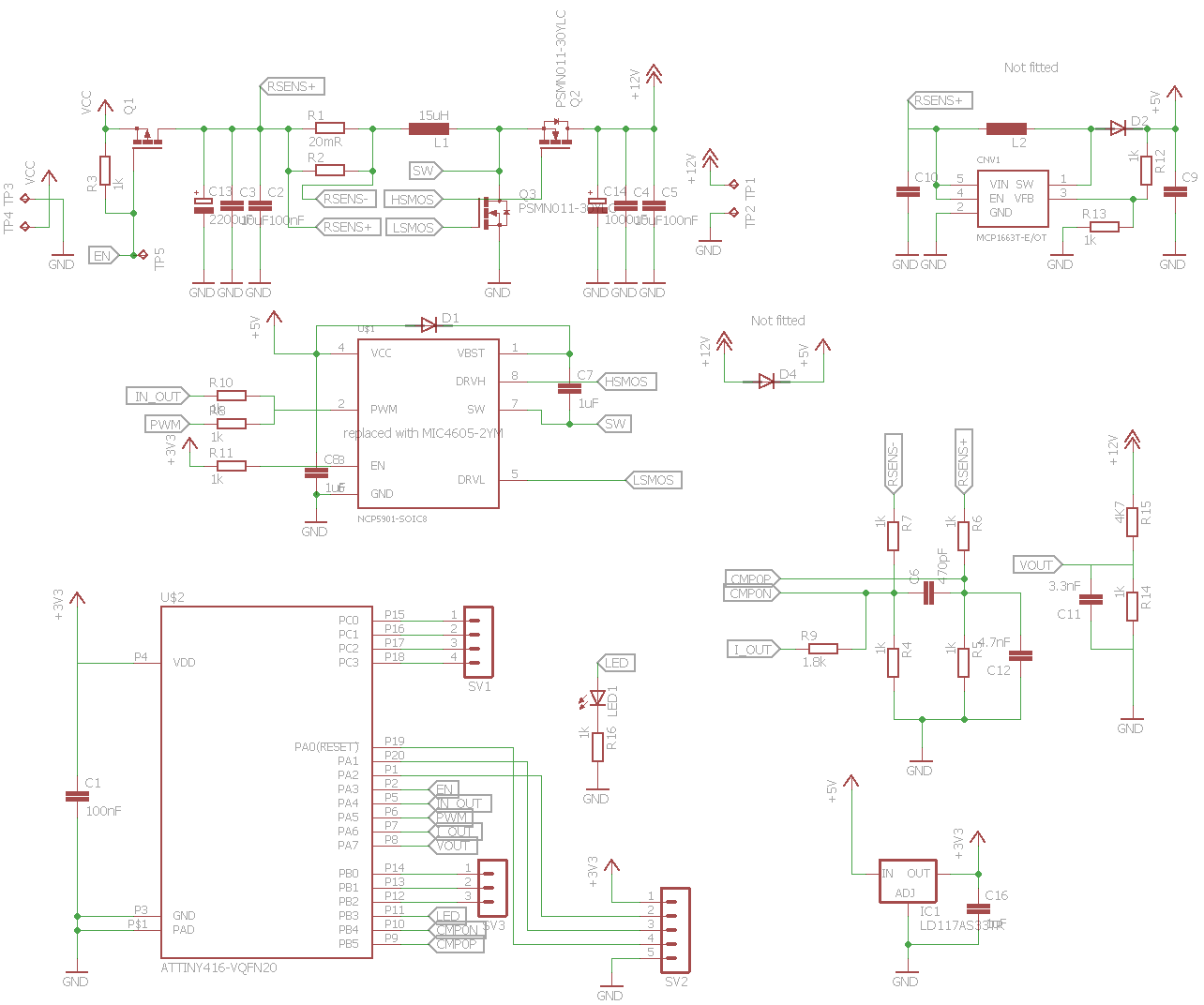
05/30/2019 at 14:21 • 0 commentsI come up with first schematic to test the idea. I went for cheap microcontroller with the fast ADC, DAC and Analogue Comparator (Attiny816). I considering other microcontrollers and possibly outside peripherals like faster ADC but I settle for peripherals build in into attiny for now. I experiment with Mosfet drivers on the beginning I tried NCP5901 because of tri-state input capability. Unfortunately build-in safety features for driving only buck converters kept shutting down the driver with internal fault. I switched to MIC4605-2YM which is simpler but requires higher supply voltage. The rest of the schematic is simple and some of the components are not even fitted for the test PCB. See the schematic and board design bellow.
![]()
![]()
Universal battery
Universal stackable energy storage device capable of receiving and delivering power to the same common low voltage bus (12V).


