Version 1.2B released
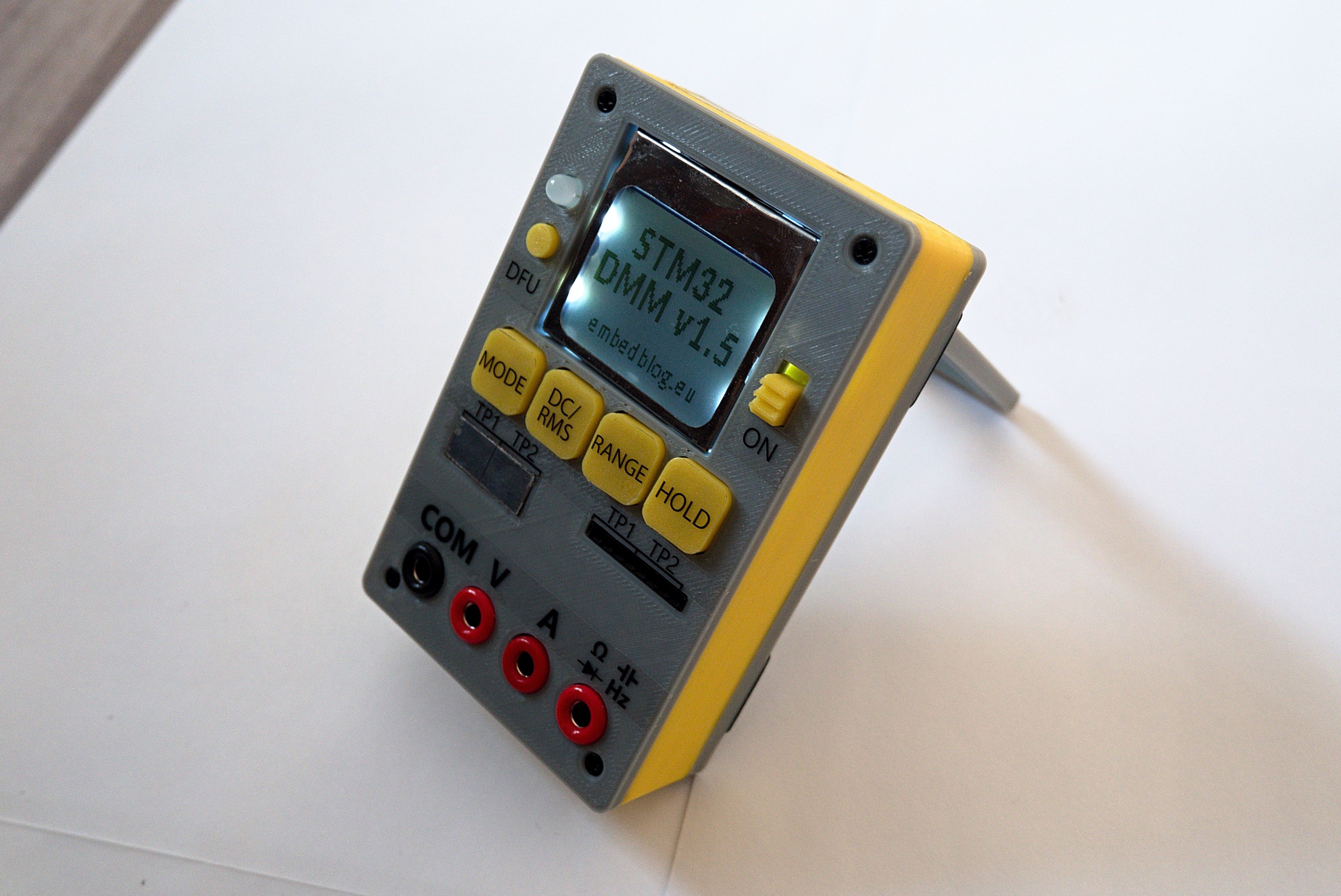
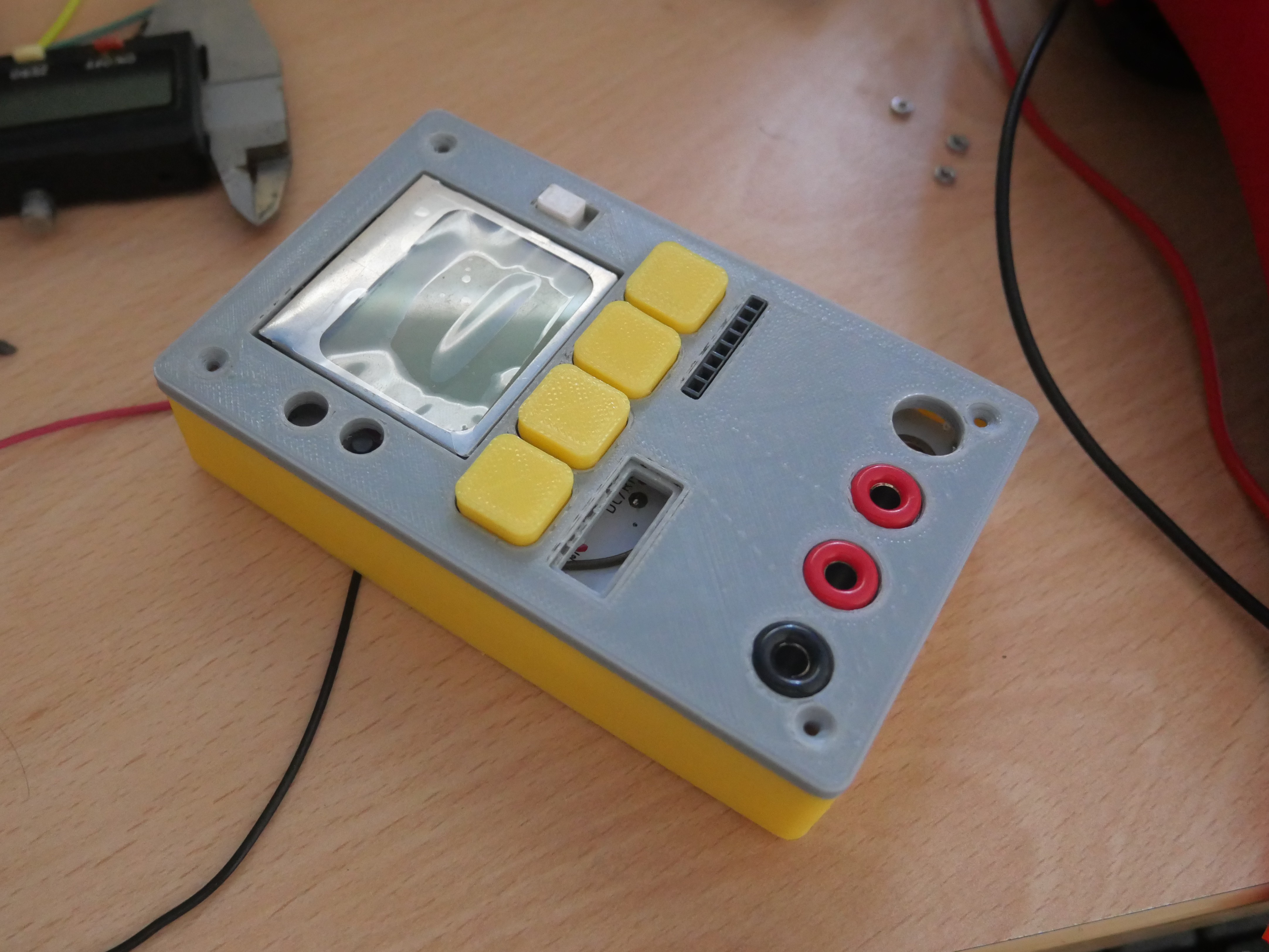
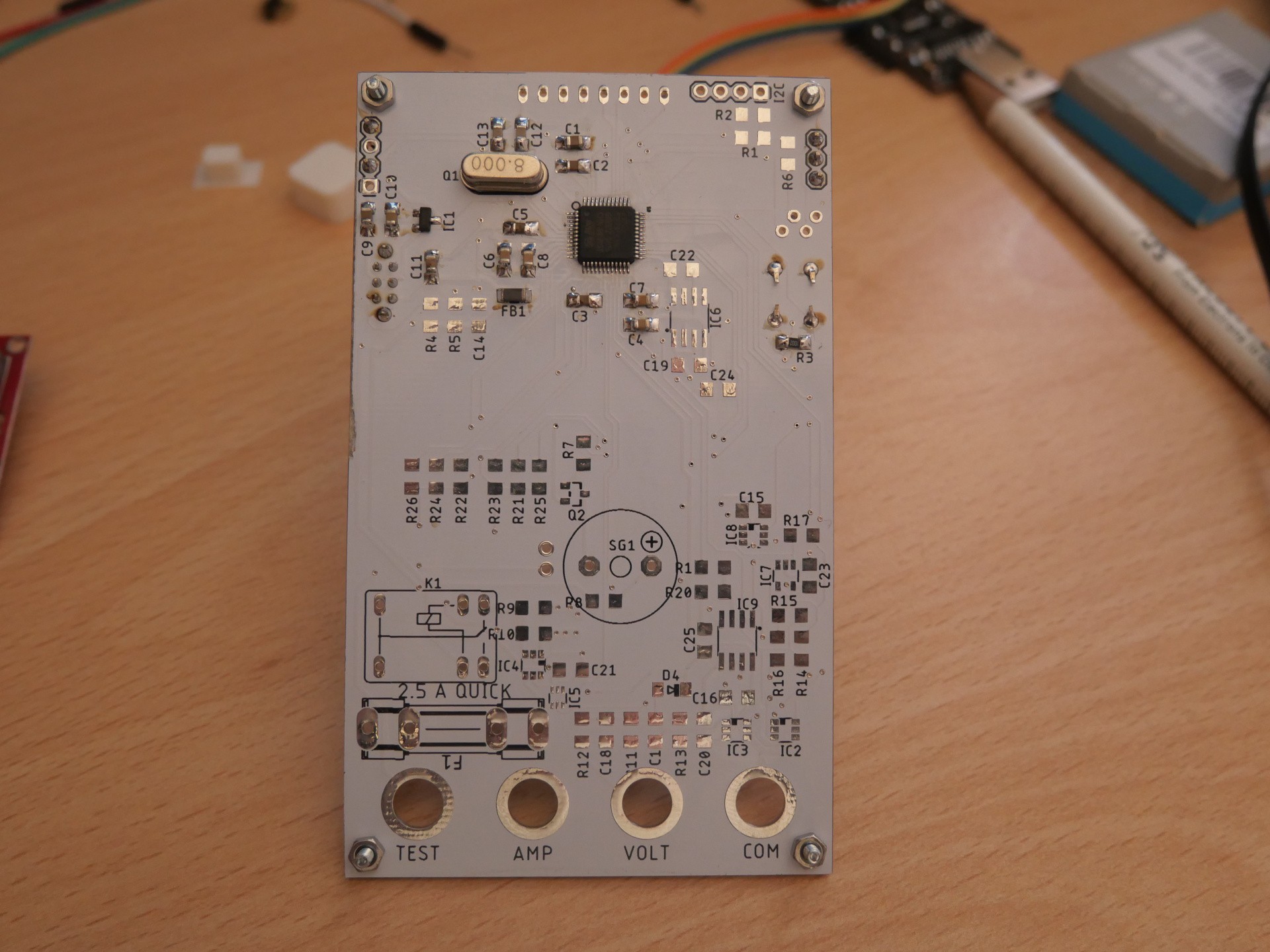
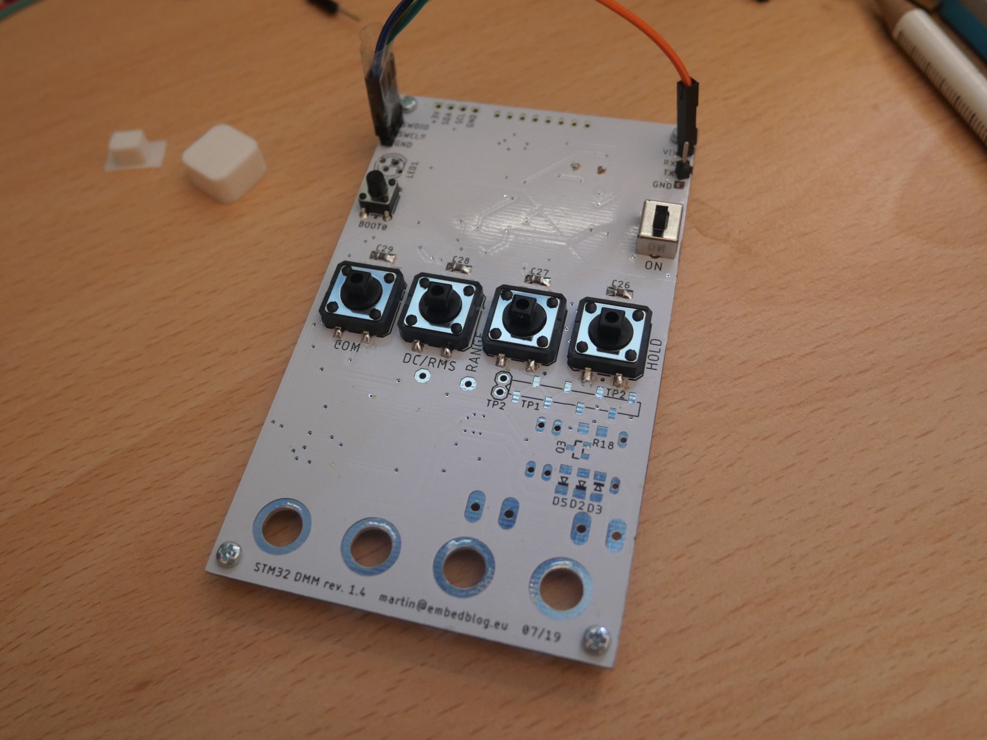
So, after a few revisions I decided to publish this project. Now I am not going to describe how everything works and all of the details, if you are interested in that, read the article on the project homepage. Here, I want more to summarize what it can do in short (more in-depth description on the project homepage)
So, what does it do? It has six modes:
- Voltage mode - measures voltage with two ranges, ±6 V and ±60 V. Ranges are switched electronically, there's a hold function (to freeze the display) and you can select between DC (or average) mode and RMS (bandwidth about 3 - 10 kHz).
- Current mode - basically the same as voltage, ranges are ±60 mA and ±500 mA, again switched electronically, again with DC/RMS.
- Power mode - yep, it can do both voltage & current at the same time, so I wondered, why not make a power mode? This comes in really handy when working with power supplies (or, just today, I used it for testing a bunch of small solar panels). All 4 combinations of ranges are possible, and you can again do RMS or DC.
- Continuity screen - basically it tests resistance and if it's below 50 Ohm, it sounds the buzzer.
- Component test - this can measure resistors, capacitors and diodes (so far). Basically I use it mostly for sorting parts after prototyping or when I need to clean a pile of parts (then it comes really handy).
- About screen - well, it tells you the name of this project.
Furthermore, some other features:
- fully isolated USB interface (capable of both receiving commands and transmitting data)
- powered by li-ion (protection & charging included) or anything with a voltage of 3.2 to 5.5 volts
- measures battery voltage and signalizes low battery
- RTC & memory, so it remembers the mode you last used
- voltage & current inputs protected against overrange
What it does not do:
- it does not measure mains, nor is it meant to; I rarely use mains, so I don't need this function, and because of safety I did not even try to implement it
What it could do in the future:
- frequency measurement (it's just a matter of writing the software for it)
- additional voltage range (± 60 mV), coming in rev. 1.3, hopefully
- and some other fancy stuff, it's described more in detail on the project's homepage
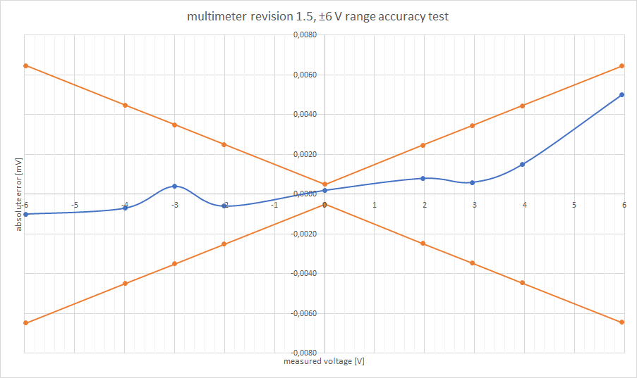
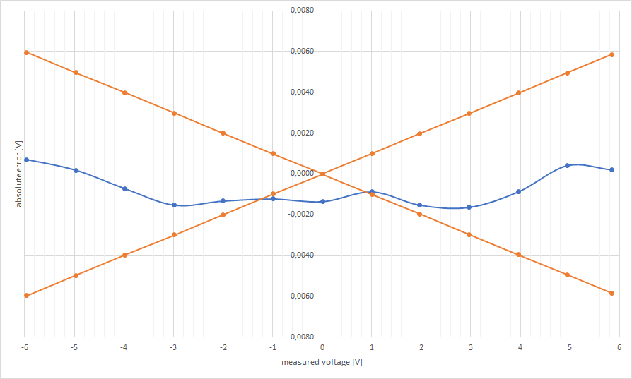
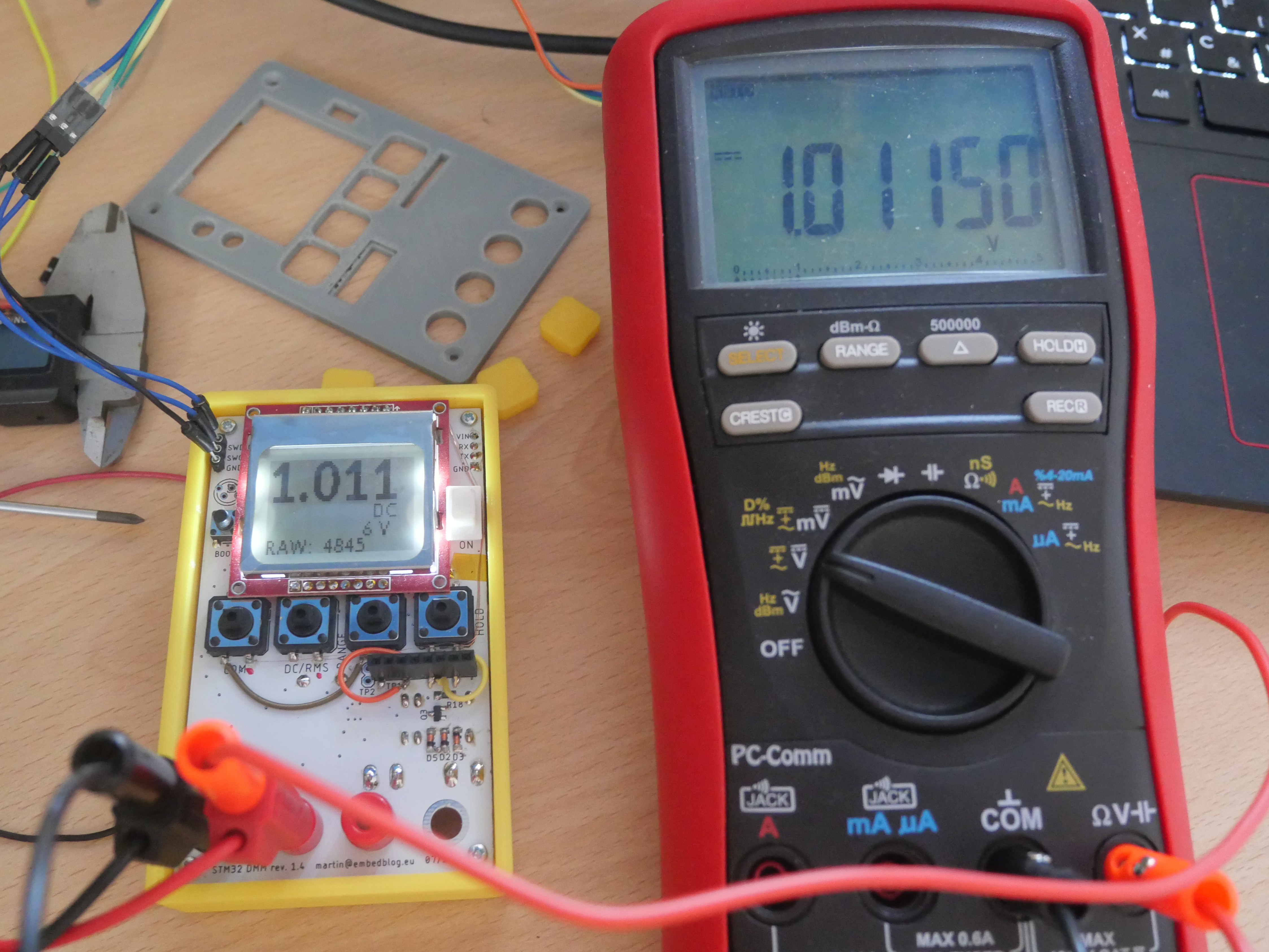
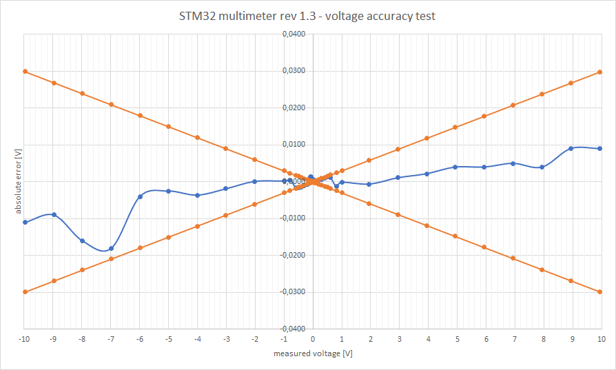
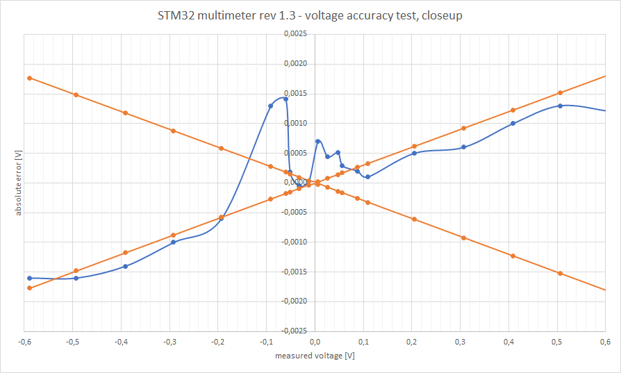
Frankly, I originally build this just for myself, but after seeing the results, I decided to publish it. Yeah and it also took a lot of time, so I thought it would be a pity to keep it to myself. Here's , for example, accuracy on the ±6 V range:
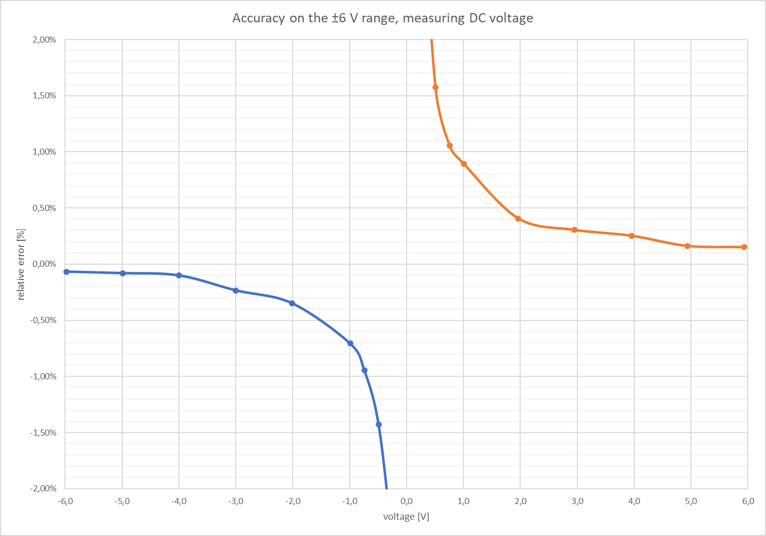
Note: some of the resistors during this measurement were 1 % ones, because I ordered wrong 0.1 % ones.
But still, I'd say this is pretty good for something this cheap- for most of the range, we are well below 1 %, which is more than enough for prototyping and/or general lab work.
Do you find it interesting? It's open source, and everything is on GitHub. Some more info is (and more will be coming) on the project homepage at embedblog.eu/dmm. Currently I have PCBs of version 1.3 ordered, it will take some time for them to arrive, but I'll post an update once they do.
Also I'd love to hear your experience/opinions/questions, so feel free to comment.
 Martin


Hey there any chance I can find the source code not compiled?