Just a quick announcement: I am currently working on a new revision, because I have a lot of ideas which could improve this project or add a lot of new functionality. I am explaining it more in depth here: http://embedblog.eu/?p=615 The current status of revision 1.6.2 is that PCBs have been drawn, ordered, and they actually arrived just yesterday, so stay tuned for the improvements and new features this version will hopefully bring! I'd put a picture or two here, but for some reason the button isn't here.
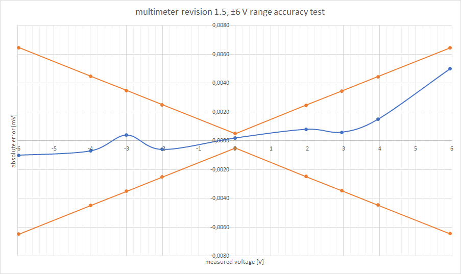
If you read my last log, you know that I am satisfied with this revision. The upgrade to STM32F373 was totally worth it - all the extra analogue features enabled me to reach accuracy of ±0,1 % plus minus a few least significant digits. And I believe that with a more careful calibration, you could do even better. For a price of around 15 dollars and all the functions it has, I think it is pretty amazing. Here's for example accuracy on the 6 V range:
The yellow lines represent ±0,1 % FS ±5 LSD.
Here's again a short video demonstrating it during use:
What now?
The project is finished. I am making more than a couple of these for my lab and I intend to use them as a daily multimeter for electronics development. There are still things in software which need to be done and things which could be done - I'll work on these and release a new SW revision soon.
So far the multimeters work reliably, the only thing I don't like much are the buttons (which are much harder to press and clickier then I would like). Also, what I found out as a limiting factor during developent was the display (which also looks ugly, IMHO) - the DMM could measure more information, actually, but there is just nowhere to display it. So what I have in mind as a future project (which I do not know if I'll ever find time for) is a similar device, but with a 2,8" touchscreen, closer to a benchtop DMM. This would allow you to log your measurements, display more values at once & with bigger font, setup warnings, show histograms, more modes of operation would be possible & switching between them would be faster...
Well, time will show if I ever start that project. For now, all the files for this one are open source on GitHub or on my blog.
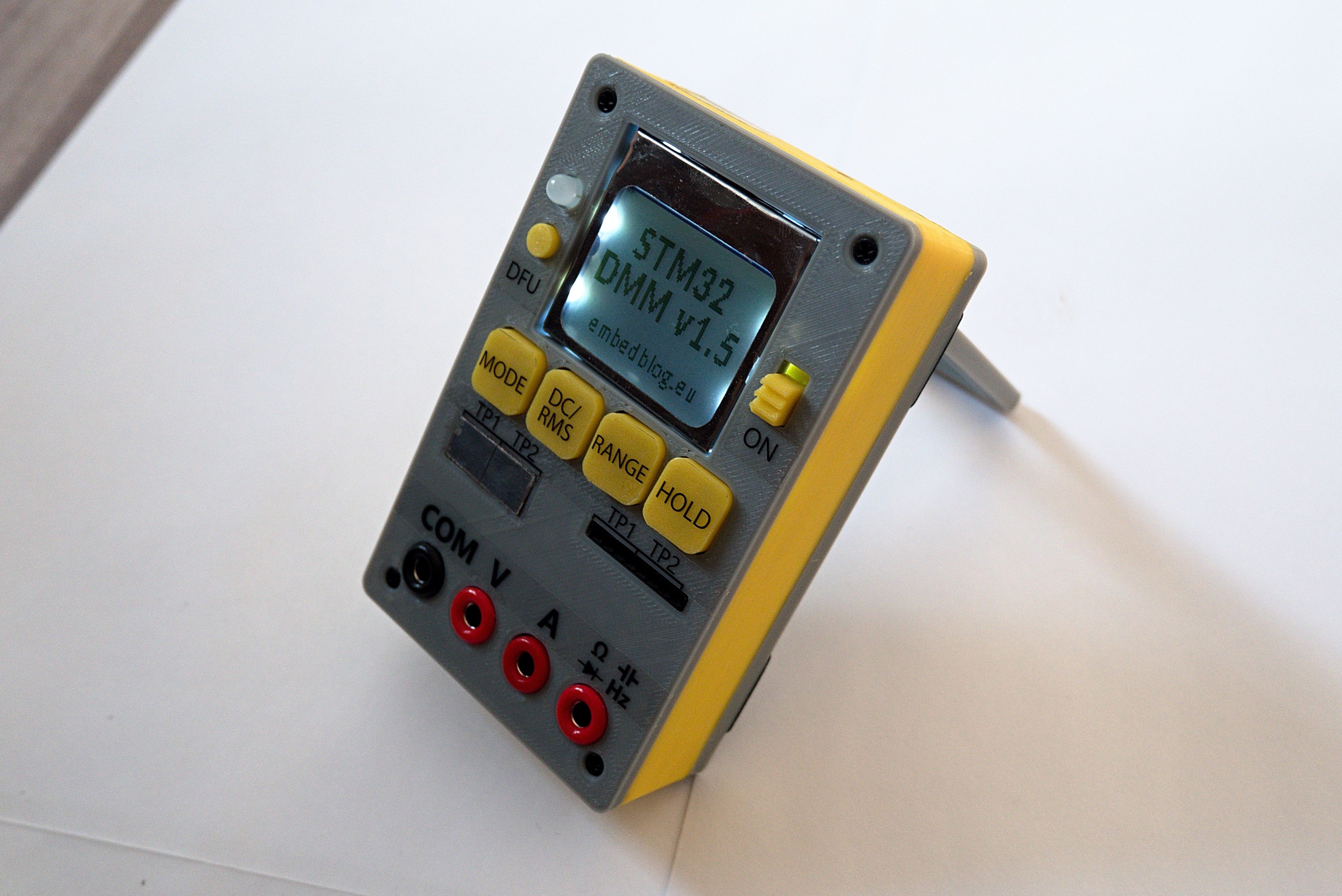
I have finally arrived at the point where this project fulfills all goals I have given it. I'll release the source files along with an article (summarizing all functions, old and new) soon, hopefully before the end of this week. But before that, here's just a little teaser of the finished DMM:
I've written a short blog post about some of the caveats I've stumbled upon when developing revision 1.4, and there's also some more info about revision 1.5. See here, if you are interested.
Well, as usual, I've spent much more time than I anticipated or wanted on the revision 1.4. So in this log I'd like to show where I got in the last two weeks, because rev 1.4 is still not finished.
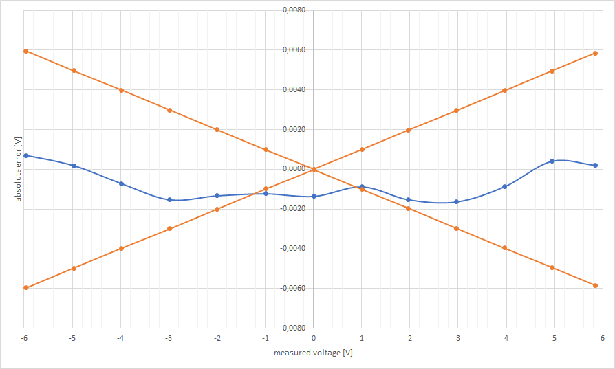
If you've been following this project for at least a little while, you know that I switched the microcontroller from STM32F103 to STM32F373, because the latter is optimized for mixed signal processing and has much better ADCs. This new sigma-delta ADC is what prolonged the development so much - it is actually not easy to use it at all, there is very little documentation available and honestly, some of the claims made by ST are just wrong. But yesterday I finally managed to get acceptable results:
And I think those are more than acceptable results - the orange lines are 0,1 % tolerance. In other words, on the ±6 V range, the largest error we got was 1.6 mV. This almost makes it a true 6000 count meter, since this corresponds to the least significant digit. With this new ADC, we also have better resolution (16 bits), true differential inputs, dedicated REF pin and higher bandwidth (50 ksps).
And now is the time for bad news: this ADC needs calibration (albeit very simple one). This is generally true for most sigma-delta based converters, even though I was hoping I'll be able to avoid it. But the results are unusable without it. It is however true that most commercial multimeters are calibrated (since most of them use sigma-delta ADCs) and also the calibration is very simple - you just measure ADC values at the top positive and top negative value and input this into a special excel spreadsheet I made.
Another bad new is that this version won't be final - I made a few silly mistakes (as you can see from the photos) and the hardware will need to be modified a little.
And lastly, two photos from development:
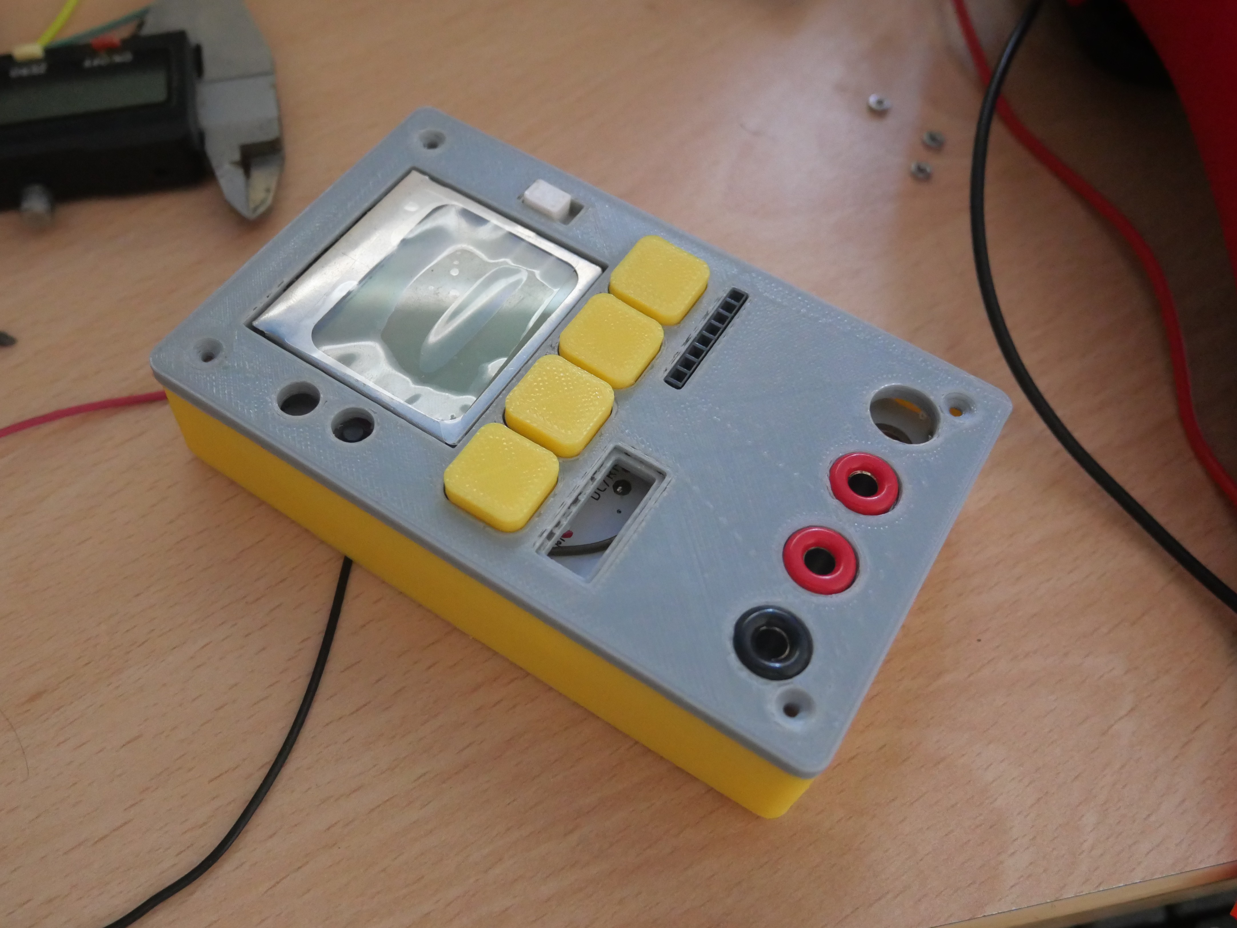
The new case I designed - I'd say this looks 100 % better than the old one.
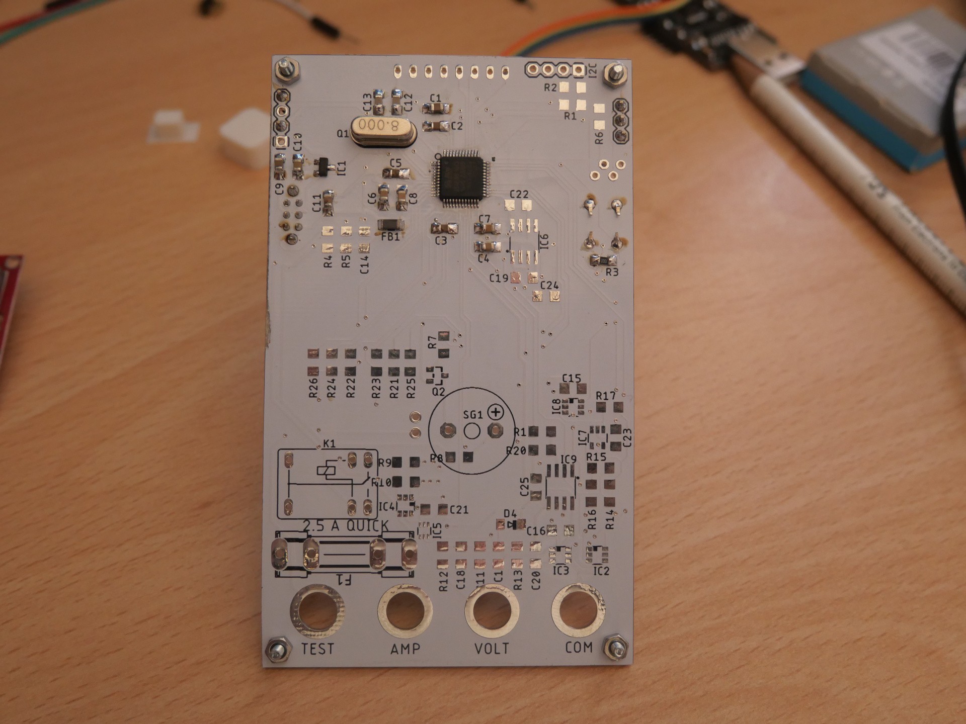
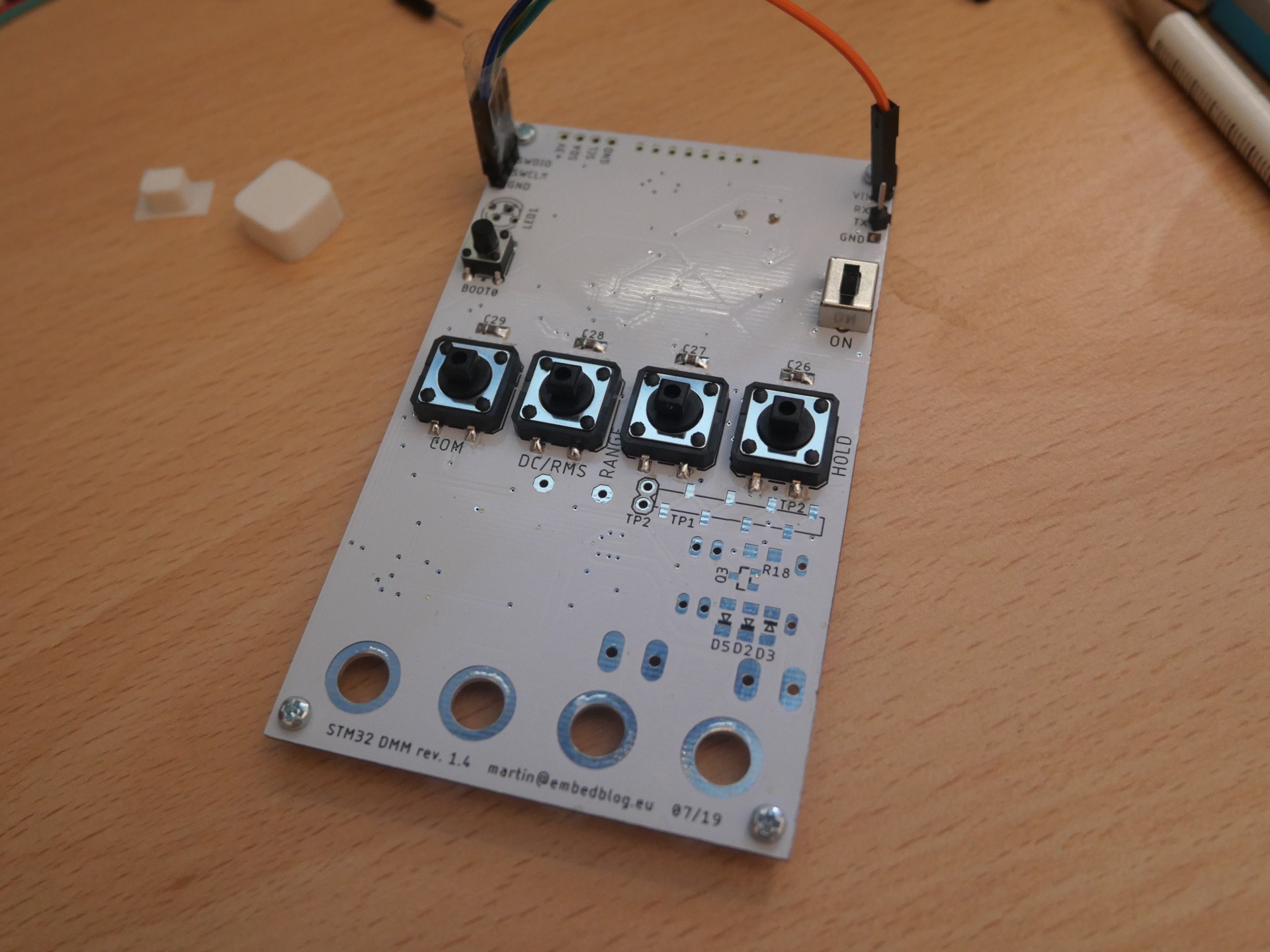
Finally, I received the long-awaited PCBs for revision 1.4 of the multimeter. I have high expectations from this version, so we'll see. I think I might have some preliminary results to share with you within a week - I started populating the PCBs immediately as you can see from the photos, so I hope to have it finished ASAP.
The PCB is totally redesigned to accommodate the new STM32F373CCT6 microcontroller. While drawing out the PCB, I also thought in advance about the 3D printed enclosure, so I hope that this version's enclosure will look much better. I also got rid of the ungly "button board" and instead used 12 mm SMD switches, onto which you can glue 3D printed risers.
On a different note, I finally decided to stay with Keil uVision as the projects toolchain. I spent about ten days trying out different IDEs and compilers, as I want to make this as open-source as possible. However, none of the IDE's I tried fulfilled my expectations, there was always sometimes missing. So I'll stick with Keil and try to fit the code into the 32 KB size limit of the free version.
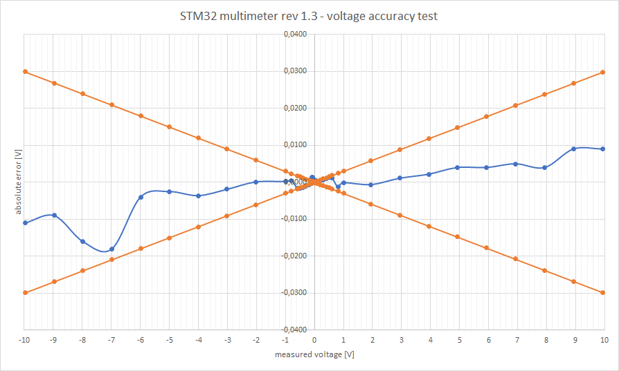
Today, after a long wait, the PCBs and components for the revision finally arrived. I managed to find some time to populate the boards and now I am bringing you the results of the voltage accuracy test.
Now in the last project log I said this revision should have three voltage ranges - ±60 V, ±6 V and ±600 mV. To be honest, I kind of lied, because it has four voltage ranges, the three mentioned above and a ±60 mV one! I just wasn't sure how well will it perform, but according to my tests, it is totally usable. The only downside of this new AFE is that the lower ranges (especially the ±600 mV one) need to be calibrated with a simple offset. I'll try to remove the need for calibration in future revisions.
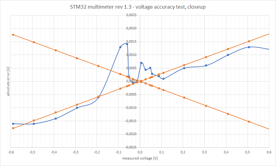
But enough talking, let's see the results:
The blue curve is the absolute error in volts, the orange curves are the maximal error margins for ±0,3 %, which is my target accuracy for this revision. Just for reference, ±0,3 % is the accuracy of the Brymen 805s, which is a 53 euro DMM! Now let's see a closeup of the sub one volt part:
I'd say this isn't bad at all.
And just to keep everybody informed - I hope that tomorrow I'll do tests with the new current stage and then I'll release the source. However, that will end the development of this revision and I will move onto 1.4, because this revision was intended mostly as a test for the new analog front end. Revision 1.4 will include this new AFE along with a much better processor - the SMT32F373, which offers a 16-bit delta-sigma ADC with differential inputs and external reference. This should vastly improve the accuracy, I am hoping for at least 0,1 %.
So, I have my batch of PCBs for rev 1.3 ordered and on the way. It will still take some time for them to arrive and for me to populate and test them, but just as a quick summary, here's what I am hoping to achieve with this revision:
±600 mV range (so now there will be three voltage ranges)
much improved current sensing circuitry with lower sense resistances and ranges of ±2.5 A and ±300 mA
frequency compensated dividers for voltage sensing
the ON-OFF switch is now just a SPDT, because the DPDT version was hard to get
general layout improvements and little changes
Also, the software still needs a lot of work, so I would like to polish it a little bit more, add autoranging, make the software remember the range you last used in given mode and also implement proper UART/USB control (so it can be fully controlled from a PC using the isolated USB interface).
By using our website and services, you expressly agree to the placement of our performance, functionality, and advertising cookies.
Learn More
 Martin