 Eric
Eric-
1Let's Lay Our Circuit out on the Breadboard
First things first, layout the components we need to use for the circuit.
![I used white LEDs but you can use what ever color you fancy.]()
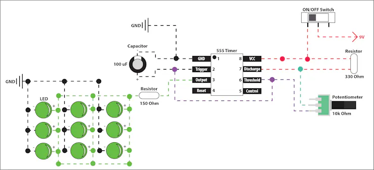
Using the diagram below, place the components on your breadboard. Note that only 2 of the 3 leads on the potentiometer are used.
![555 Timer Potentiometer Circuit]()
If you placed the components correctly your LED should start to blink at an increased speed when you adjust the potentiometer.
-
2Now Let's Design our PCB!
With our circuit mocked out and working on the breadboard let’s design it in Patchr and make a PCB. Below is a new diagram that shows how the additional 8 LEDs are laid out. I added power lines on either side of the LEDs to make sure we had even distribution and there was as little dimming occurring across the LEDs.
![555 Potentiometer Circuit w/ 9 LEDs]()
First thing we need to do is create a new project and start drawing the footprint of our PCB. I wanted mine to be as slender as possible, so I measured the width of my 9v battery (26 mm) and made it the width of the “handle" of my PCB. Due to the limitations of the build volume of my Bantam Tools PCB Mill, I made the height 120 mm with a little wiggle room.
![]() You can really make it whatever size/shape you want but I was going for a Men in Black Neuralyzer feel.
You can really make it whatever size/shape you want but I was going for a Men in Black Neuralyzer feel.Now that the footprint is drawn, let’s place the components. I made sure to leave room for the 9v battery to sit double sided taped to the back of the PCB so all the components should be higher up on the board. I placed the switch and the potentiometer on one side of the board so that I could easily adjust the speed with one hand. I went ahead and annotated the screen capture with what values go where for each component.
![I annotated the parts for better identification.]()
The 555 timer comes in a generic PDIP package (8 pins with 4 evenly spaced on 2 sides) so we can use any 8-pin through-hole IC, I chose the ATtiny85 for this layout. A few helpful shortcuts to speed up your layout:
- Copy & Paste: Select a component on the board, press Command + C, Command + V
- Rotate a Component: Select the component then select and hold one of the corners of the bounding box or Command + R
Now we will use our breadboard design and the diagram above to route our PCB! Here are a few helpful keyboard shortcuts:
- Switch to top side of the PCB: Command + 1
- Switch to bottom side of the PCB: Command + 2
- Rotate a component: Command + R
- Toggle pad view vs component view: Command + P (removes all the components icons to reveal the component footprints)
- Show ghosted image of routes on the opposite side of the PCB: Command + H
![Top layer routes appear solid and bottom layer routes appear slightly greyed out.]()
Top layer routes appear solid and bottom layer routes appear slightly greyed out.
Once you are finished, hit export and send it out for manufacturing or mill it at home!
-
3Assembly
With your PCB manufactured, solder your components to the board. Refer back to your Patchr project and the circuit diagrams as you are assembling for reference.
Handheld Party Starter Pocket Strobe
Giving you that little bit of oomf you need to kick any situation up a notch.


 You can really make it whatever size/shape you want but I was going for a Men in Black Neuralyzer feel.

Discussions
Become a Hackaday.io Member
Create an account to leave a comment. Already have an account? Log In.