-
Progress update 10/3/19
10/03/2019 at 17:27 • 0 commentsI just uploaded a pdf of work to date, including various random bits of design and analysis. I have a working prototype using a Raspberry PI3
It is in the "FILES" section of this project: "new diurnal light".
-
PCB's Arrived
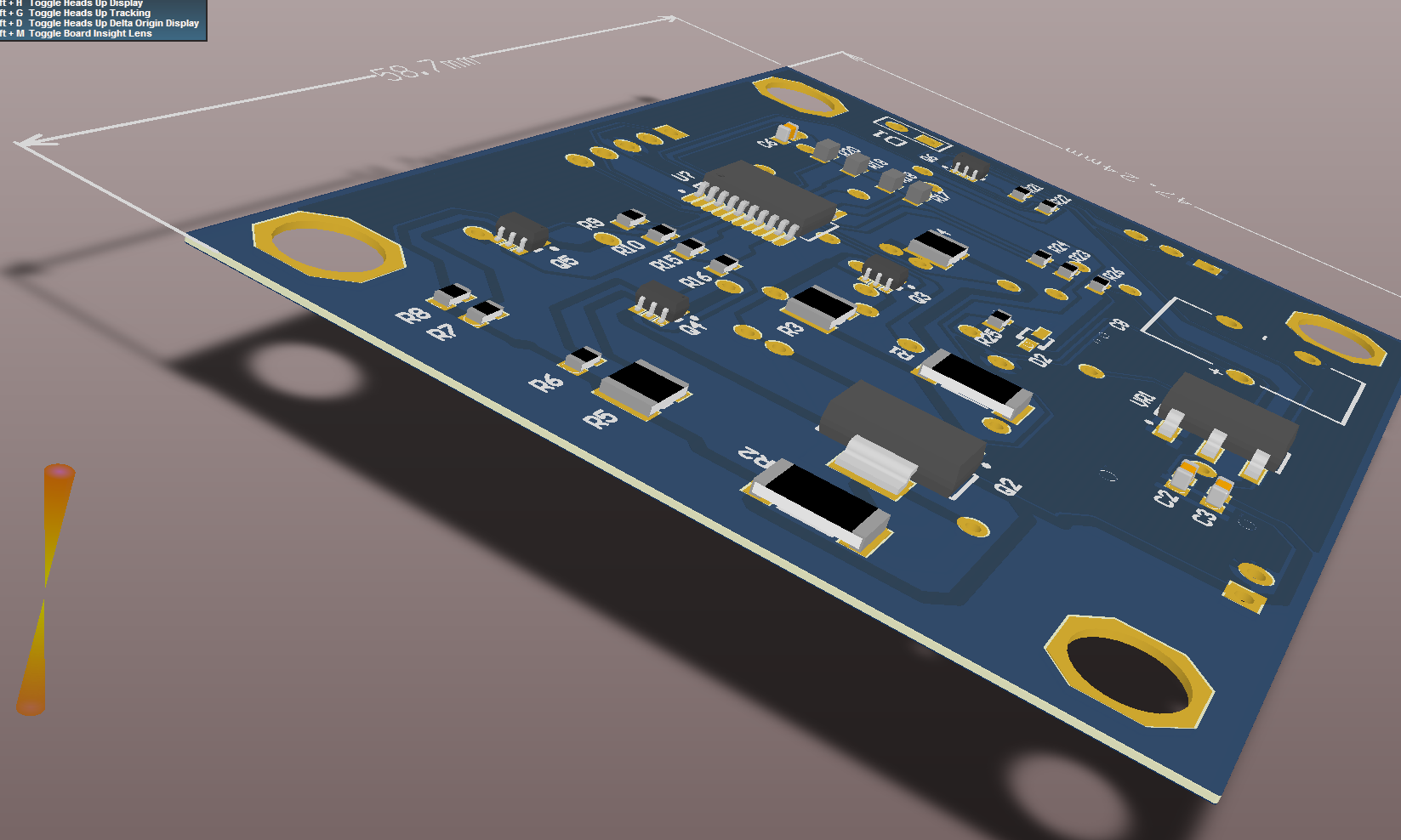
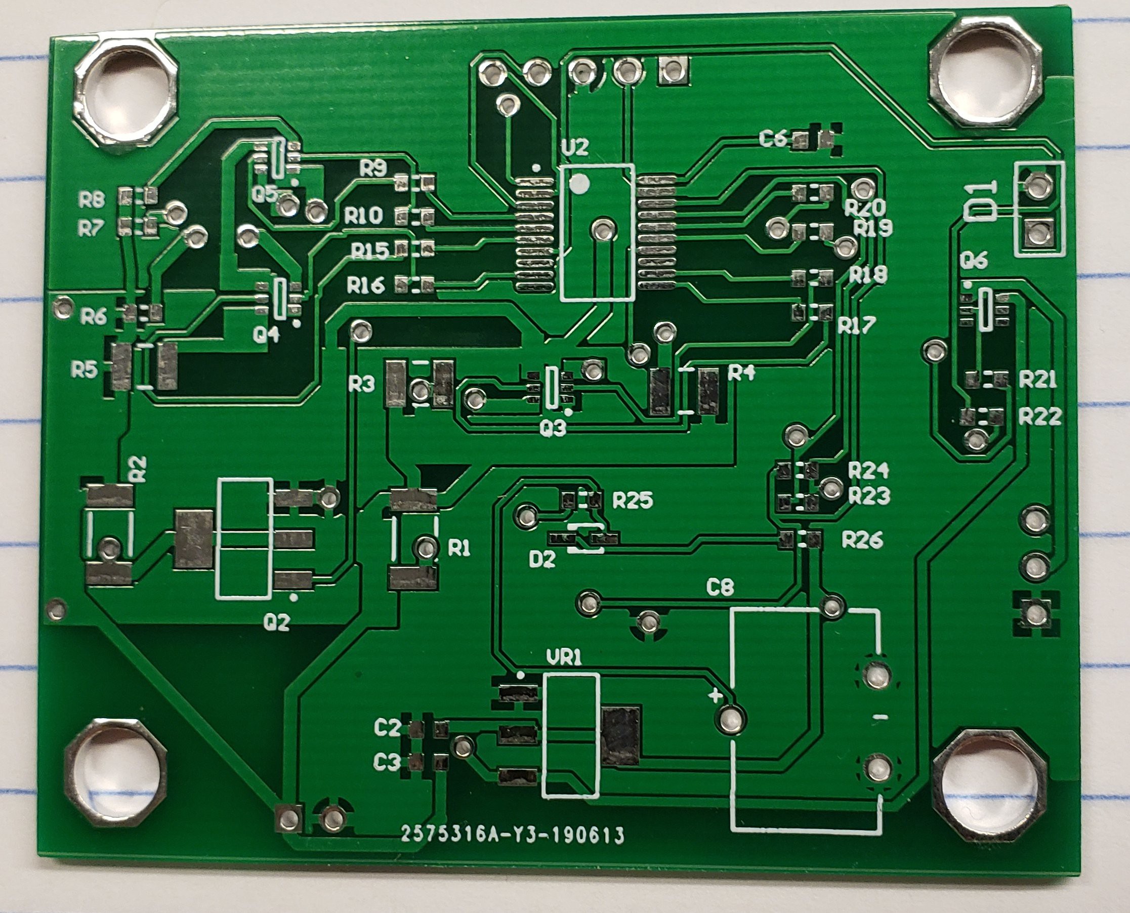
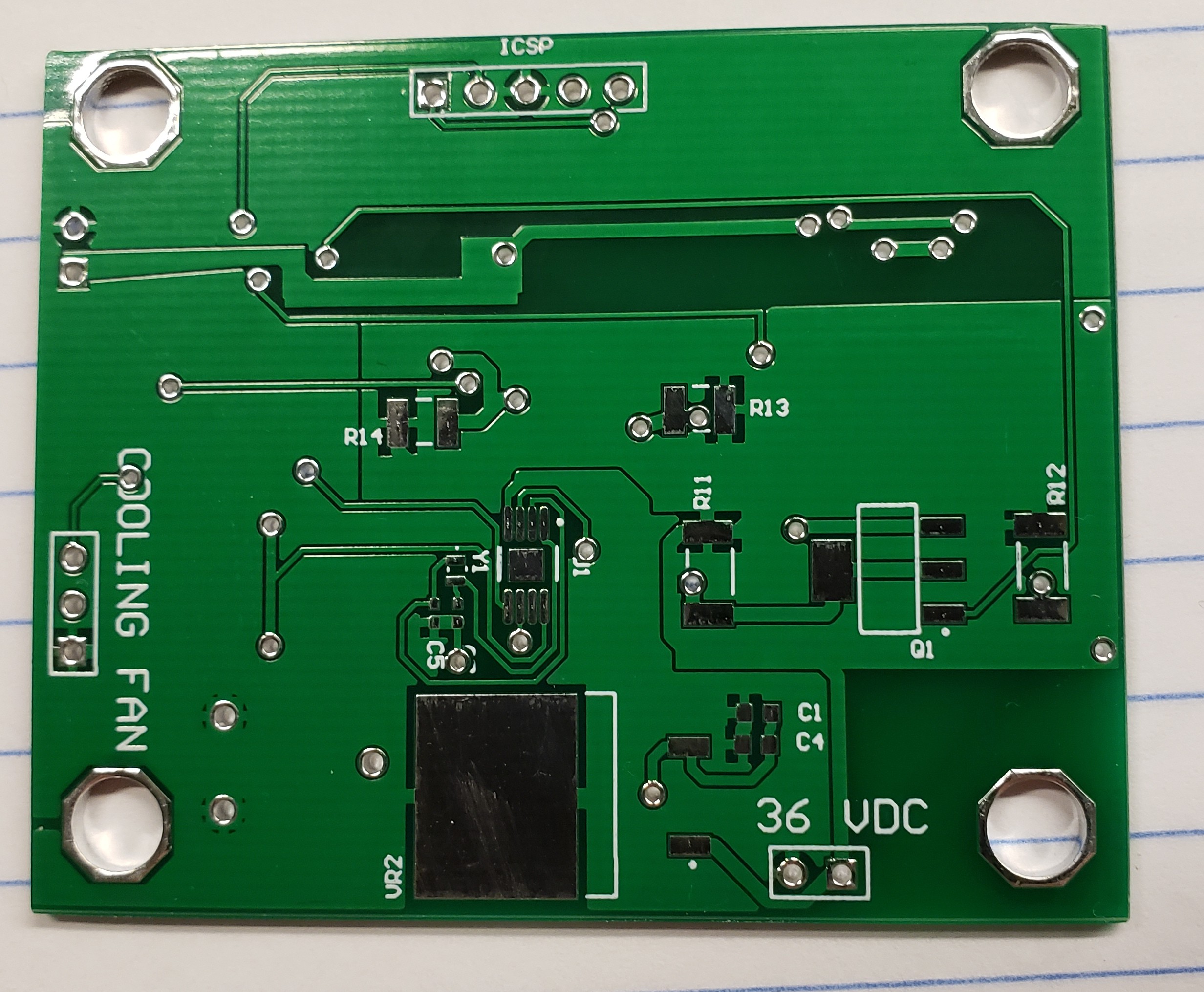
07/01/2019 at 16:59 • 0 commentsThe prototype PCB's got here from China:
..
![]()
for the topside ....
here is the backside:![]() ... not bad for $8.00 (for 5 boards) ... populating the board with the voltage regulators now.
... not bad for $8.00 (for 5 boards) ... populating the board with the voltage regulators now. -
1.05 kW LED
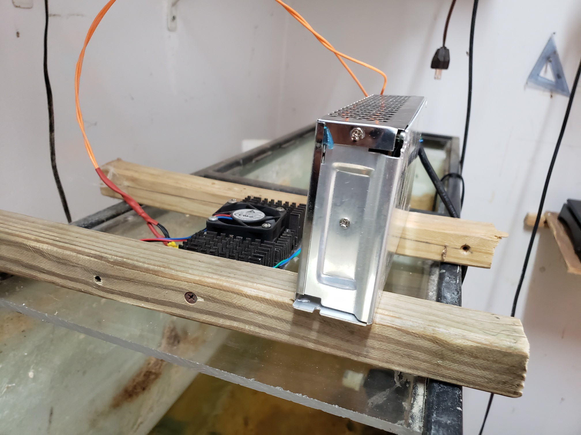
06/21/2019 at 21:13 • 0 commentsI promised information on my 3 LED prototype:
3 50 watt LEDs (each the radiantly equivalent to a 350 incandescent) 3x350=1,050 W)
![]()
and here is the backside/upside:![]() It has worked for some months ... used it for hydroponic tomatoes for a while (they loved it!)
It has worked for some months ... used it for hydroponic tomatoes for a while (they loved it!) -
Previous work with 50W LED's and reef tanks
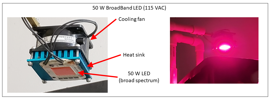
06/18/2019 at 15:21 • 0 commentsI've built and I am using some of these LED's in my reef tank setup. Most notably, I have a rigged a 50W broadband (chlorophyll absorption friendly) LED over the refugium of my 55 gal tank. It's been running about 12 hours every night for the last 6 months:
![]()
This LED uses 115 VAC. The refugium grows chaetomorpha to reduce nitrates and phosphates in the tank.I also have a three-50W LED prototype that runs on 36VDC over another tank (2 cool white's with a broadband in the middle). I'll post images of that soon.
-
A word about 50W LED's equvalency
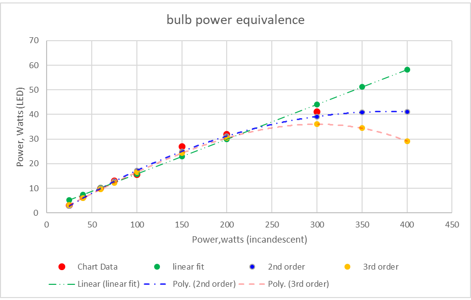
06/17/2019 at 15:18 • 2 commentsUsing a chart from Wikipedia (link here), I created the following chart in order to get some equivalency between bulbs and LED illumination:
![]()
The wiki chart only goes up to 300 W (incandescent), so I curve fit the data to get some idea of higher values. Since the polynomial curve fits show a round off beyond 300, I use the linear fit. According to that, a 50 Watt LED produces the same radiant power as a 350 Watt incandescent bulb – that should be 106 W for compact fluorescent bulbs. Of course, only the linear curve fit gets to 50W ….
-
PCB's ordered
06/12/2019 at 20:57 • 0 commentsordered proto pcb's from china ... 5 boards, as described previously, 2-sided, delivery in 14-18 days ... LESS THAN $8 !
-
diruanl curve look-up table
06/12/2019 at 15:20 • 0 commentsoh, here is the look up table for the normalized diurnal insolation curve:
hour
8-bit LUT
1
0
2.00
0
3.00
2
4.00
17
5.00
41
6.00
71
7.00
105
8.00
140
9.00
174
10.00
204
11.00
229
12.00
246
13.00
255
14.00
255
15.00
245
16.00
228
17.00
203
18.00
172
19.00
138
20.00
102
21.00
69
22.00
39
23.00
15
24.00
1
-
First eval PCB design
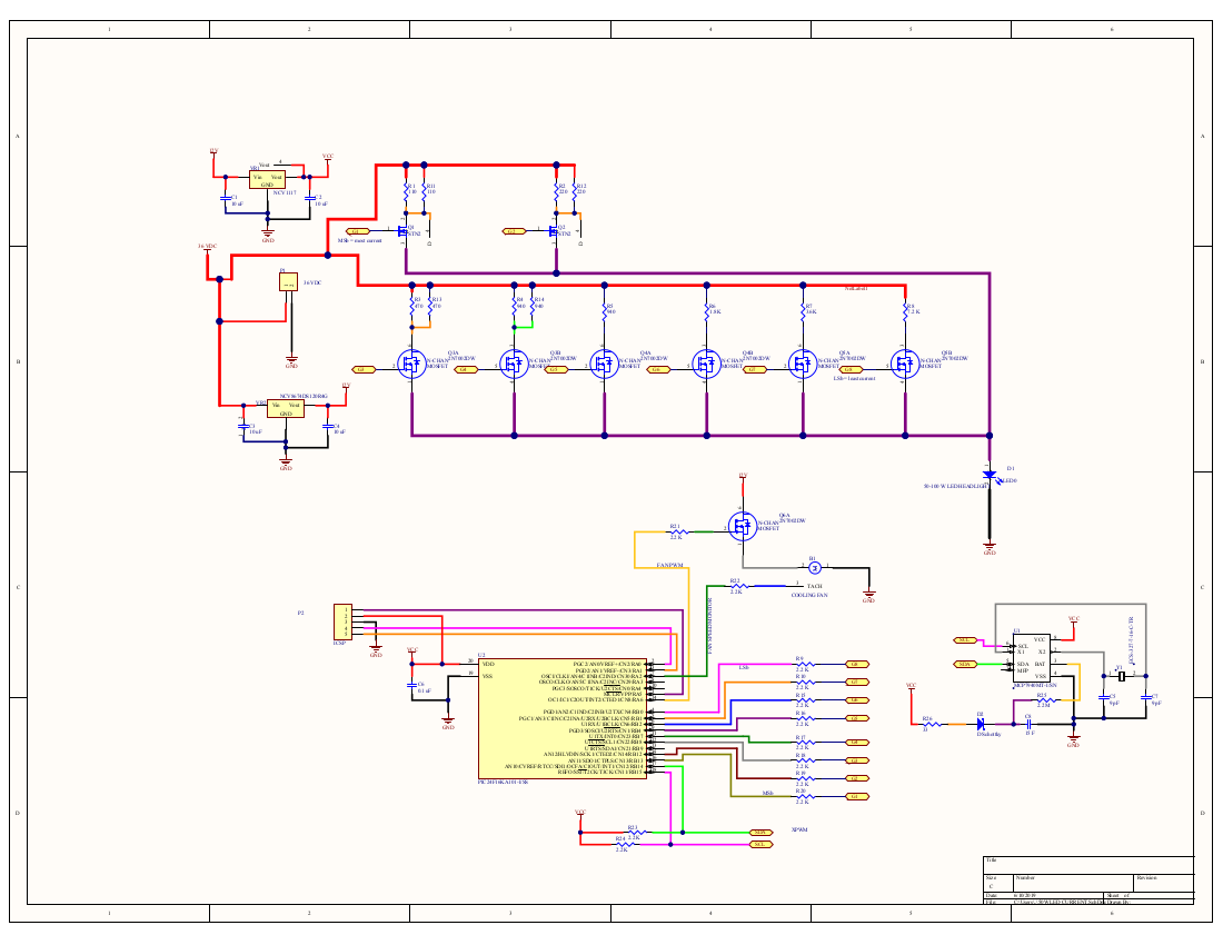
06/10/2019 at 17:21 • 0 commentsThe PCB we make will control the current with 8 bits, use a PIC24F16KA controller, and a MCP7940 real time clock.
![]()
The PIC talks to the RTC over SDA & SCL lines using I2C. Power input (P1) comes from a 36VDC LED driver that plugs into 115 VAC. Voltage regulators down-shift the 36 V to 12V (for the cooling fan) and ultimately Vcc (which is 3.3 V). You see all eight current control MOSFETs, and there is a single mosfet controlling the fan speed.
The diurnal curve previously shown is programed into the PIC's memory as a list of 8-bit integers (from 0 to 255 representing a normalized insolation of 0 - 1.0). The two-sided PCB is 59mm x 47mm.![]()
A five-pin header is provided (P2) for programming the PIC.
This should be sufficient to prove that the concept works.
Next, I intend to add an I2C flash memory to the bus.
Then add control for a blue LED (for lunar).
Then, USB ...
Then, Bluetooth, so one board can control many. -
first cut board design complete
06/07/2019 at 21:24 • 0 commentsThe first cut design of a PCB to control the 50W LED by digital current control is complete. Making Gerbers now. 8-bit control gives 256 levels of brightness from the LED.
It is important when making lights for biological systems to use CURRENT CONTROL ... not voltage/PWM. An LED controled by a PWM signal only APPEARS to brighten or dim. It's not really ... it's just fast blinking all on/all off . The strobing effect is undesirable by lots of plants and animals. On the AVERAGE, the PWM signal looks analog, but it's really just strobing digital.
I arrange eight mosfets in parallel - each controlling 1/2 the current of its most-significant neighbor, and twice the crrent of its least-significant neighbor. The most current is controlled by the most-significant bit in the control word/byte.
To control the 50W LED, the most-significant MOSFET turns 25W on or off (b7). Then next MSb turns 12.5 W on/off (b6), then 6.25 W, then 3.125 W ... etc etc.
control bit power controlled
7 25 W
6 12.5 W
5 6.25 W
4 3.125 W
3 1.5625 W
2 781 mW
1 390 mW
0 195 mW
Voltage is a constant 36 VDC, regardless of current.
Power level on each MOSFET is controlled by a current limiting resistor on the drain. The sources of ALL MOSFETS are tied straight to the anode of the 50 W LED.
50W/36V=1.4 Amps
36V / 1.4 Amps = 27.5 Ohms resistor on the most-significant MOSFET (a high power beastie, I put two 55 Ohm 12Watt R's there in parallel)
Number 2 MOSFET requires 55 ohms
Number 3 MOSFET: 110 ohms
#4: 220 ...
... you see the trend, I think
Diurnal Reef Controller for Lighting and Tides
Exactly the right lighting and tidal conditions have to occur to induce the spawning of corals (and other sea creatures).
 ... not bad for $8.00 (for 5 boards) ... populating the board with the voltage regulators now.
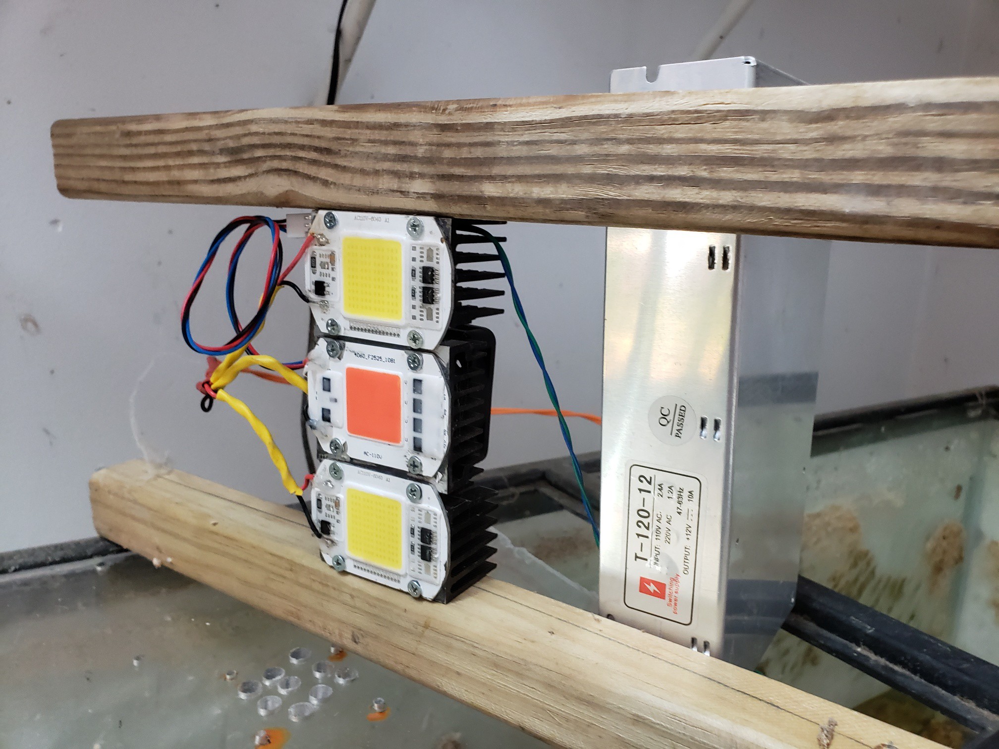
 It has worked for some months ... used it for hydroponic tomatoes for a while (they loved it!)