Close
0%
0%

DIYTIL311

A reprogrammable replica of the famous TIL311

Similar projects worth following
This is a *reprogrammable* replica of the famous TIL311 with the help of my friend Alex G. As old chips from the 70s and 80s become harder and harder to get my hands on (and more expensive), I wanted to create a replica with a modern twist.

This display is 95% accurate in terms of physical dimensions compared to the original, uses an atmega328p, and is reprogrammable. Yes a display that takes a nibble and represents it as hex is cool, but wouldn't it be cooler to be able to display more than 16 characters? That is why I made it.

THE BOARDS ARE HERE!!!

Late last year, I found Mohit Bhoite's instagram. He had posted a picture and video of an HP 5082-7415 that he was going to use in a project. This prompted my unnecessarily large order of all sorts of vintage LED displays including an HDSP-2111, a couple TIL311s, and many more.

At the beginning of this year, I stumbled upon Mile's instagram page. At the time, he posted a picture of his DIYTIL305. This inspired me to do my own sort of display board. I decided to do a reprogrammable TIL311 replica.

I didn't really have time to do anything on this because of school and work. Now with school done, I have begun work.

BTW, only at the time of writing this did I find that Mile's project is based on Alex's and Yann Guidon / YGDES's PICTIL project. Thanks to all of you who inspired this long endeavour.


  • PCB Assembly

    Jacob Still06/23/2019 at 08:21 0 comments

    At the end of the last post, I said that this one would be on programming. Sorry to disappoint, but this is not about programming. This is about putting the prototype circuit boards together

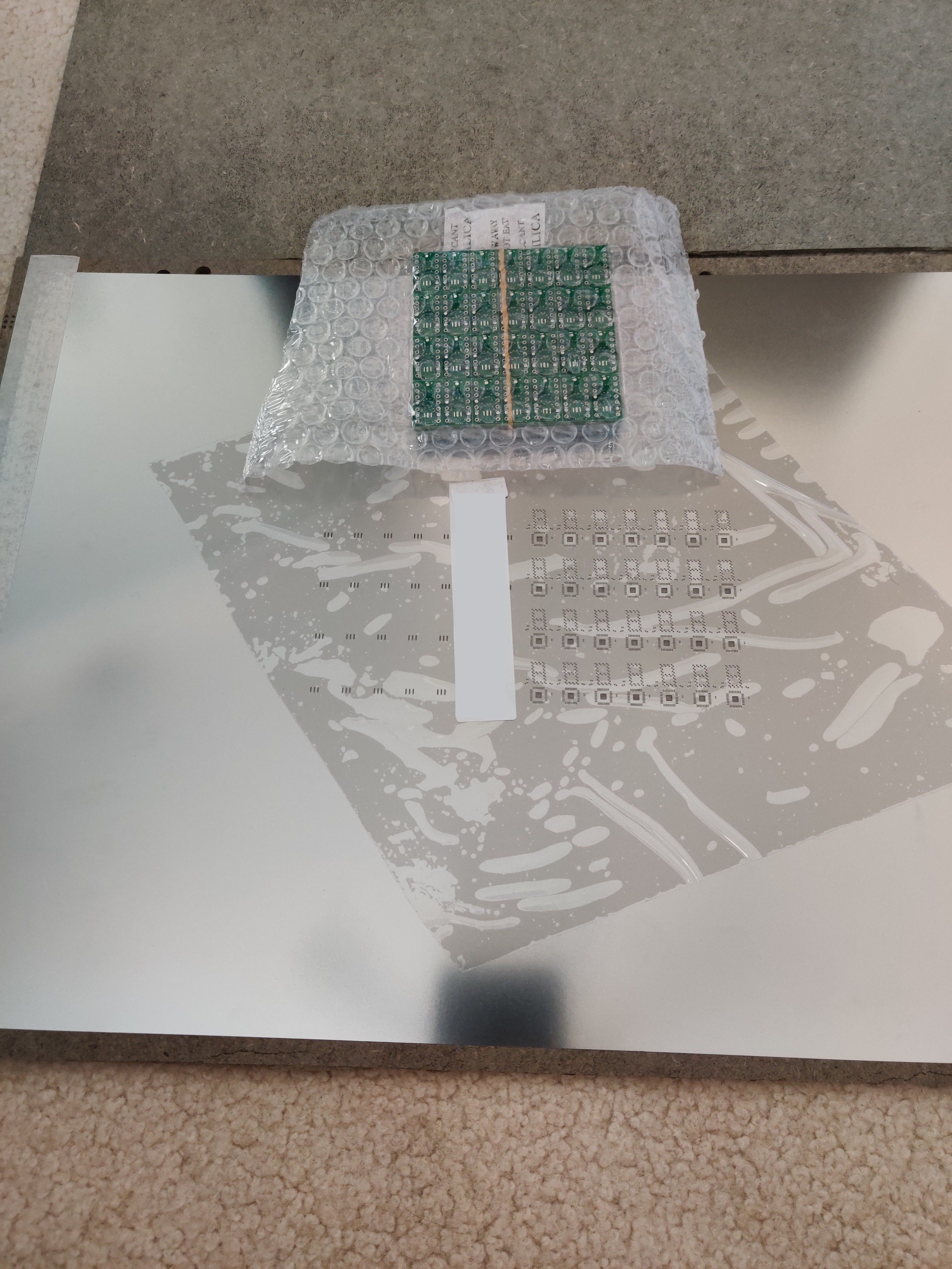
    I received the circuit boards and just about ripped them open as the postman was giving them to me. In the mail came two boxes, one with the vacuum sealed PCBs and the other with the massive solder stencil. When I ordered, I didn't realize that the stencil was going to be so big, oh well.

    Massive stencil:

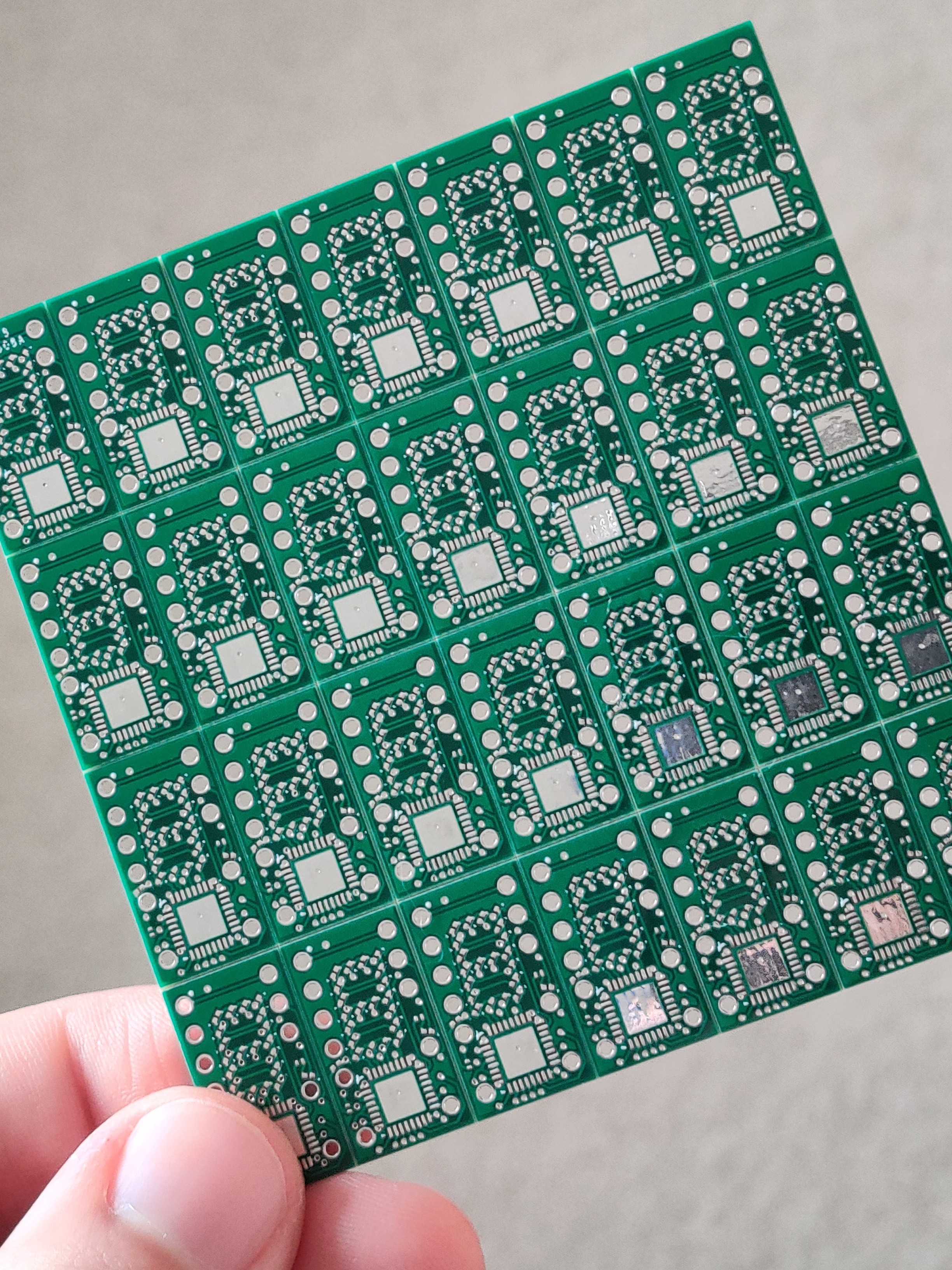
    These boards are Tiny:

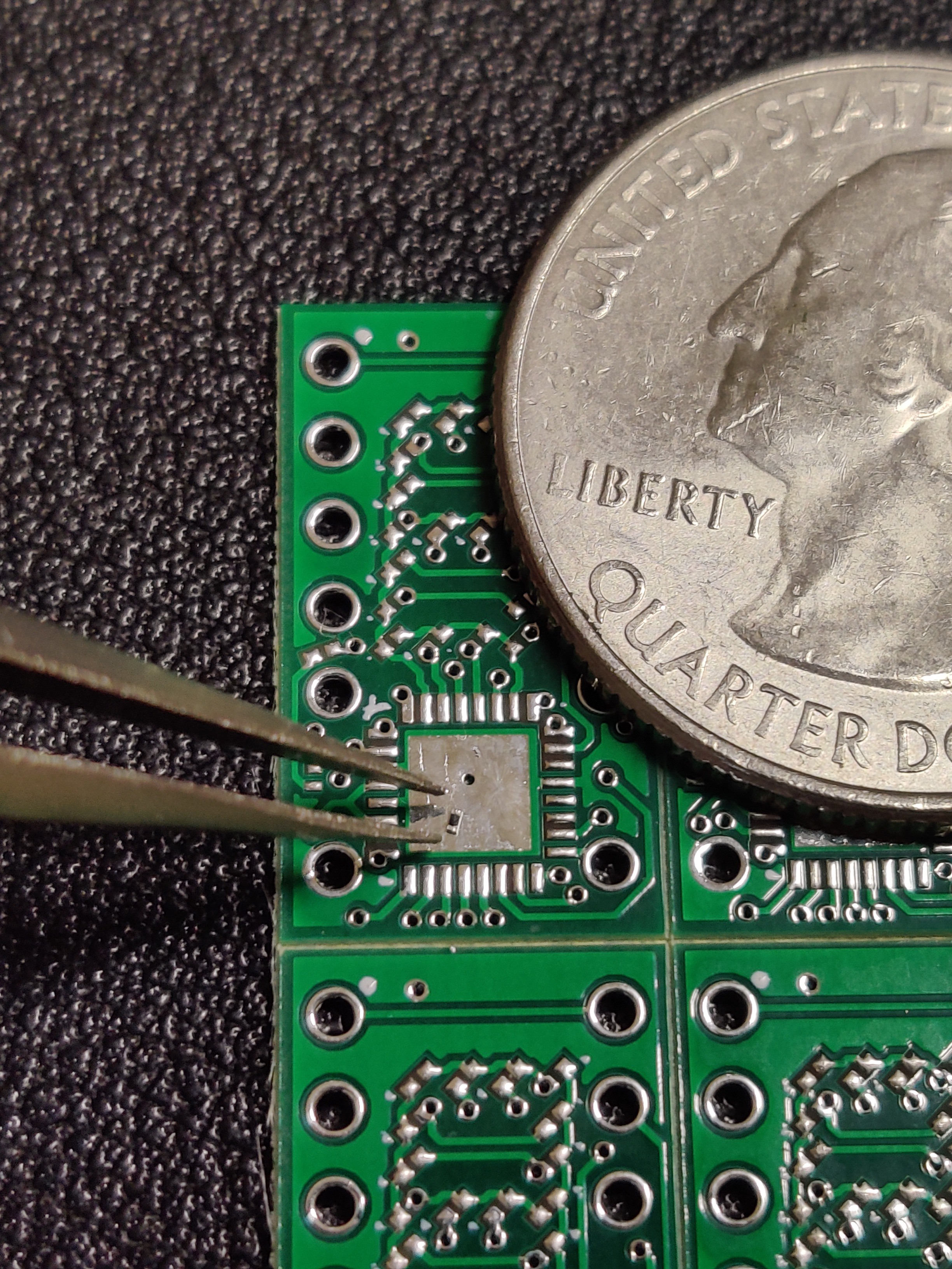
    As soon as I opened the boxes, the realization of just how small these things are set in. The microscopic size is daunting. Yes daunting. There are a total of 81 pads per board including the relatively massive ground pad under the processor, all of which are less than a millimeter in size, except the ground pad. 

    I have opted to go from easy mode - soldering large through hole components, to Super Uber Brutal Extreme Mode (SUBEM™) - soldering the absolute smallest components I could find BY HAND. This is mainly because I hate myself and like to suffer (i.e., space on the board was at a premium).

    28 pc. panel of the tiny DIYTIL311s:

    Solder Testing:

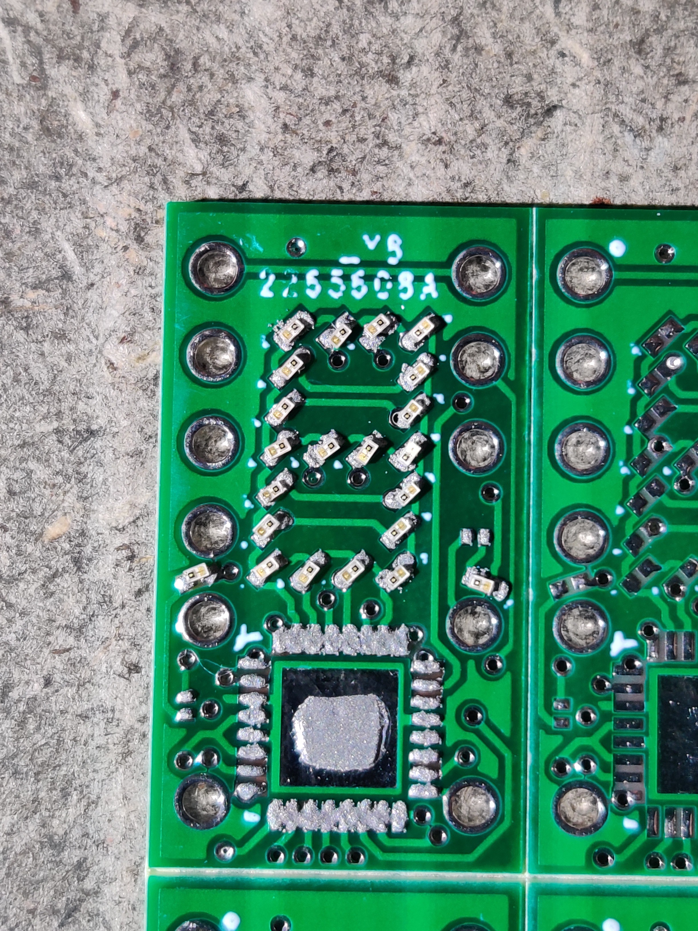
    Soldering is pretty straightforward. I didn't get a picture, but after taping down a couple boards to use as a guide, I put the board to be soldered down and lined up the stencil. Using an old gift card, I scraped the solder paste across the stencil and removed it. The result was fairly good.

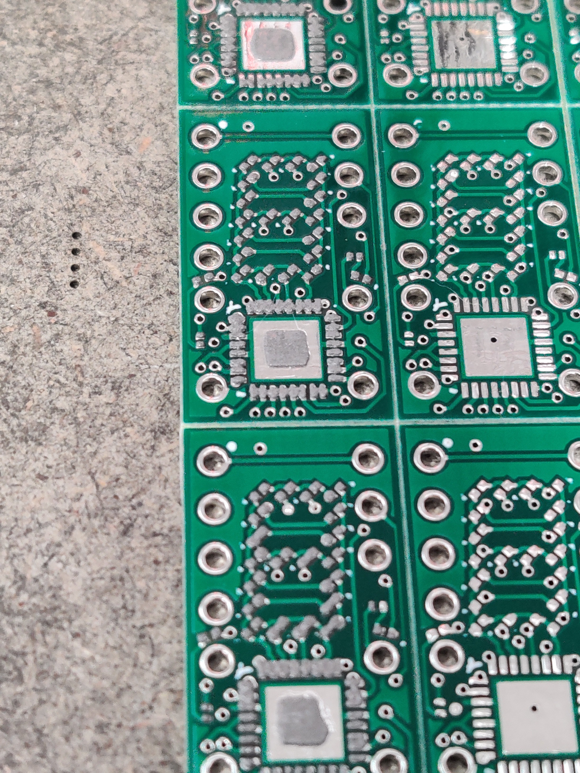
    Wet solder paste:

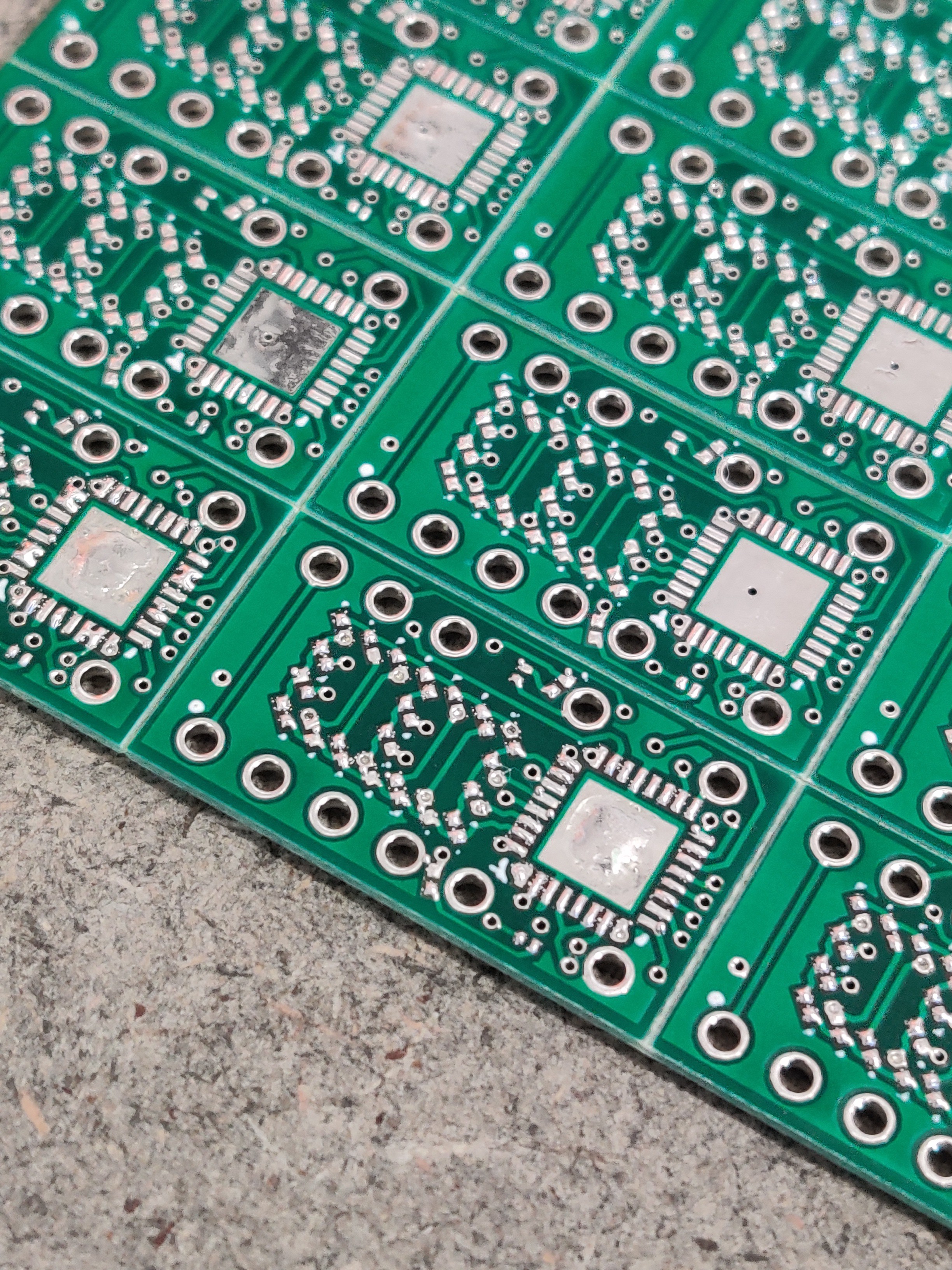
    This was my first time using solder paste, stencil and a hot air station. Because of this, I decided to use the first board as a test to see how good the stencil really worked. You can see in the picture above that the pads for the LEDs look to have good coverage, but the processor's pads are kind of overlapping. This is ok as the surface tension of the liquid solder will cause it to flow onto the pad. In the picture below, you can see that some of the pads of the processor have "bridged" across. This will not be an issue once the part is sitting on the pads as the solder will have to cover more surface area and will be sort of pulled away from these points due to surface tension.

    After flowing the solder (first row of boards only):

    Soldering the Prototypes:

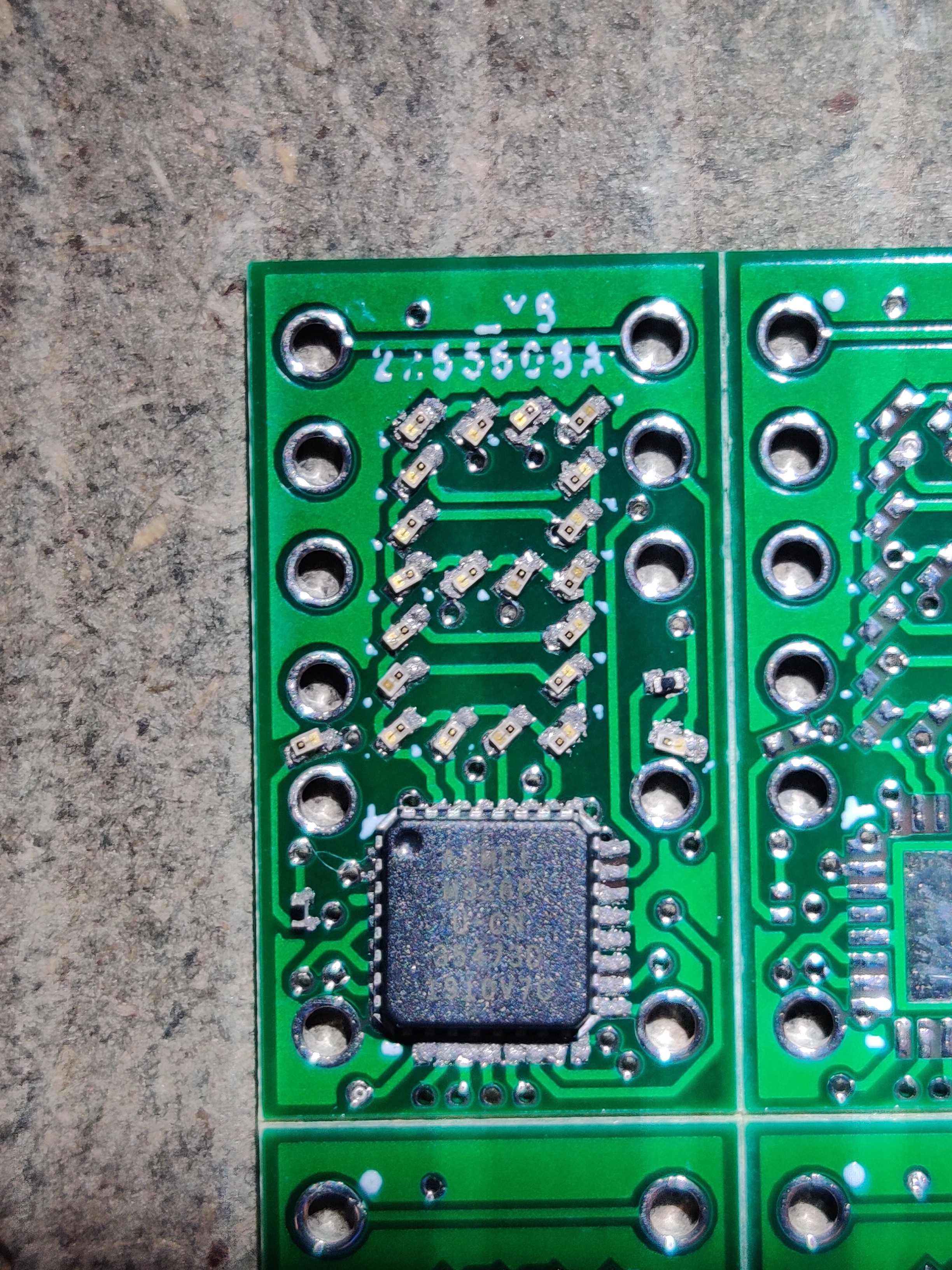
    I spent maybe an hour placing all the components. Because of the size, they tend to stick to the tweezers when trying to push them around or place them. It took some time to be able to place something this small. Thankfully, the flux inside the solder paste helped to hold the components while placing them.

    I would just like to point out just how small these components are:

    LEDs Placed:

    Resistors and Processor placed on board:

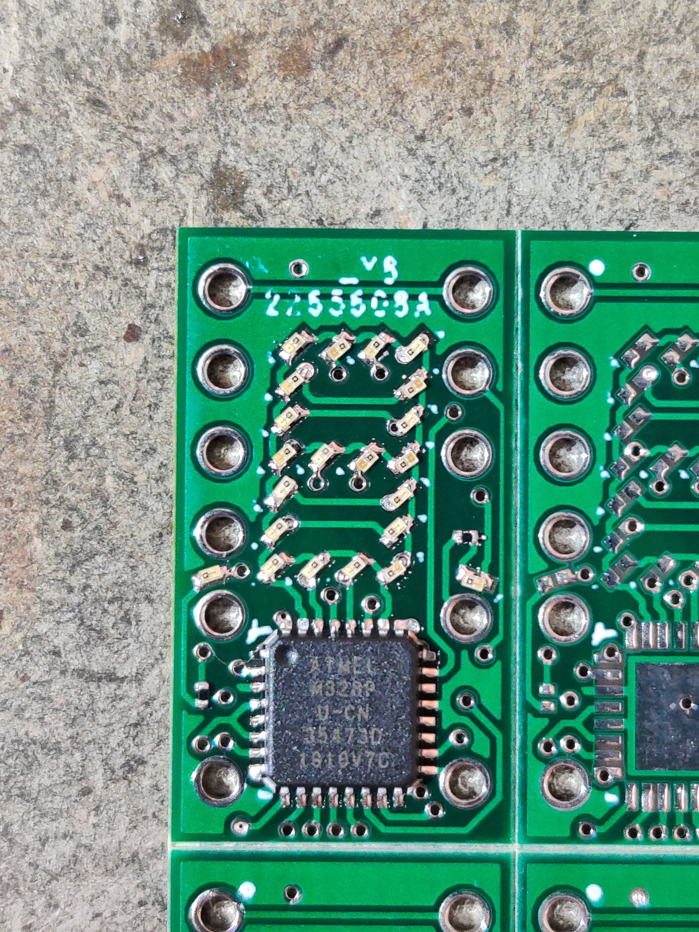
    Final board after flowing the solder and convincing some of the parts around:

    Soldering the pins:

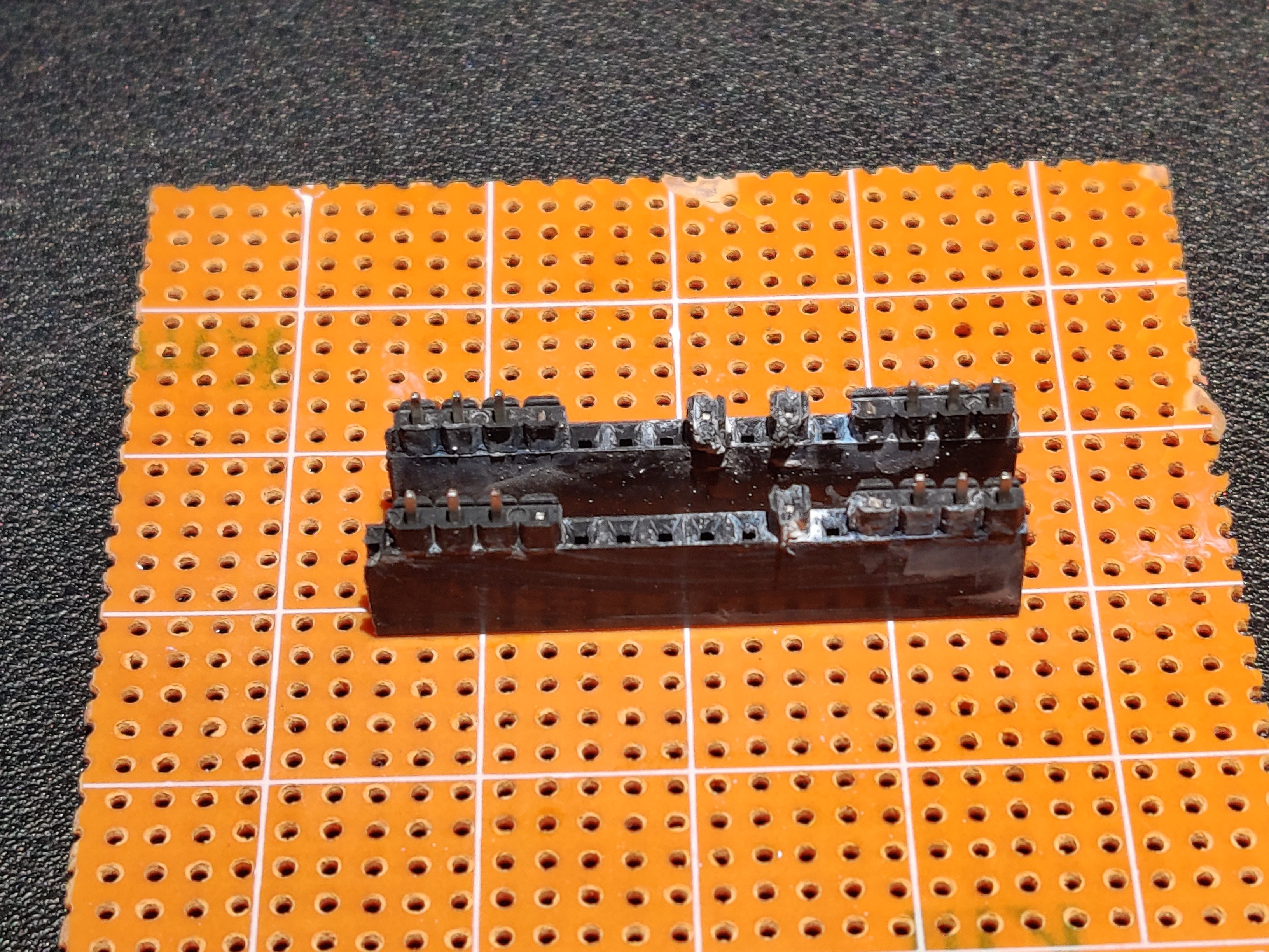
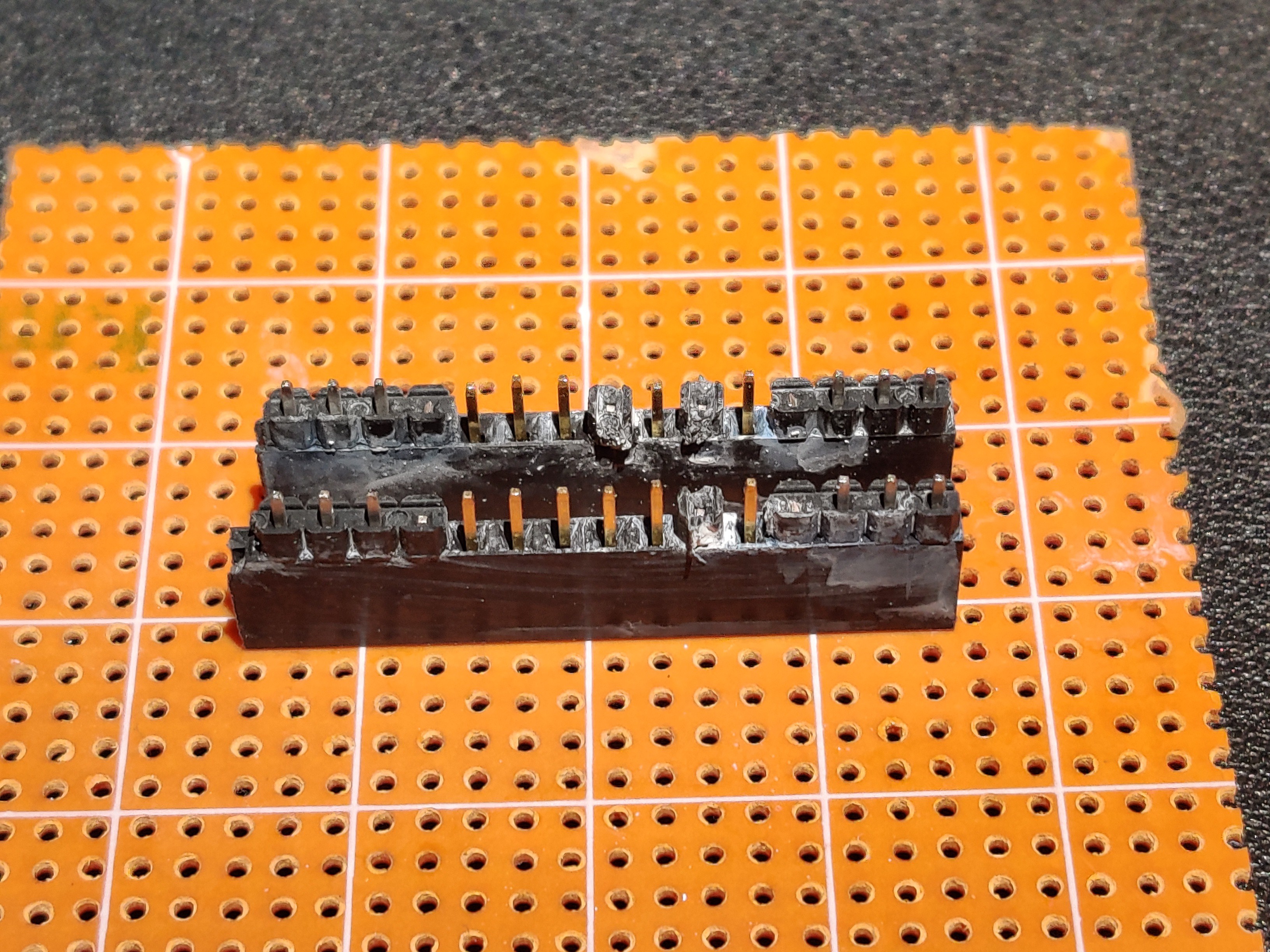
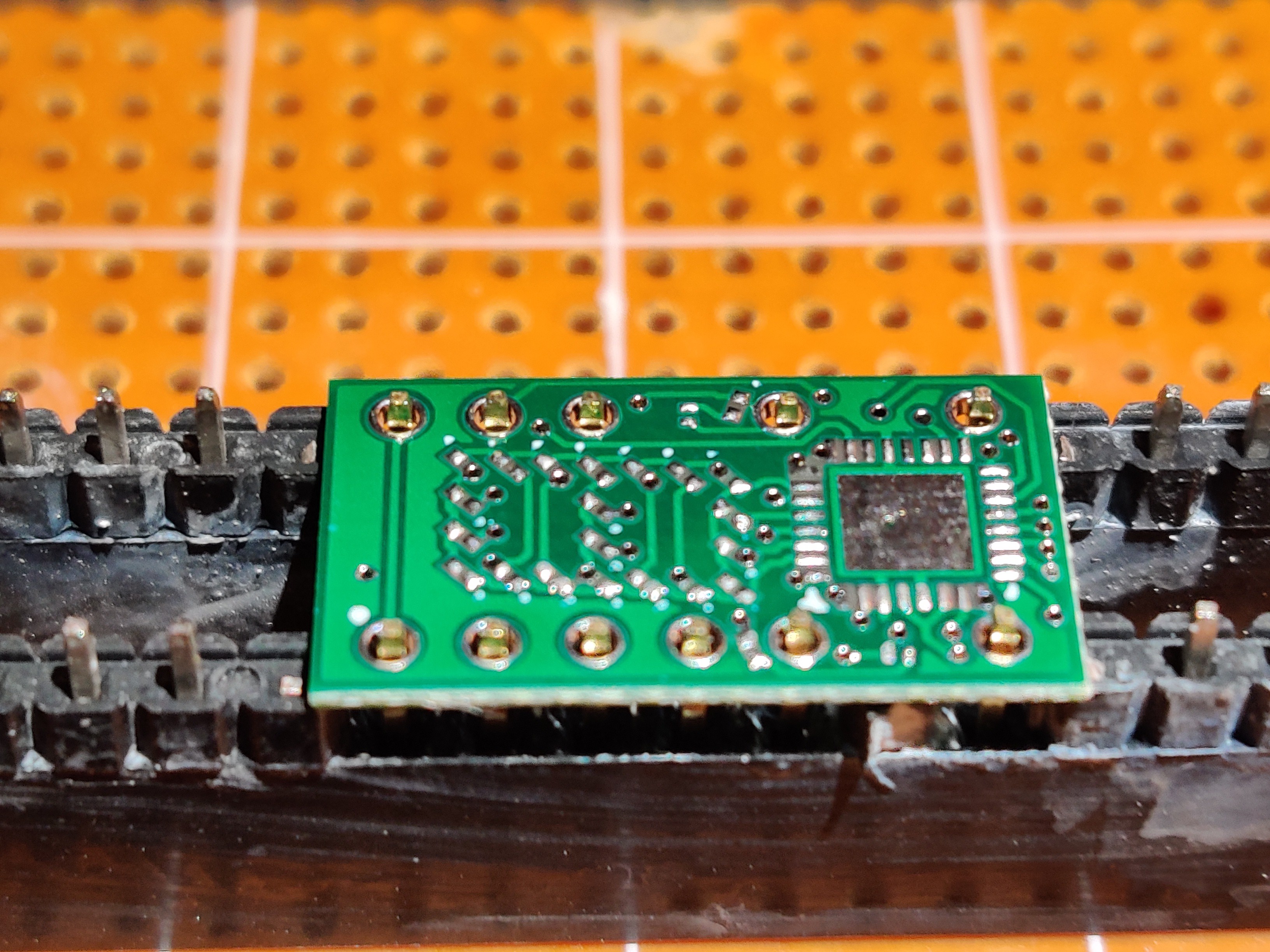
    I want this to be as accurate to the original as possible, so I made a jig to help solder pins. This way the black plastic part found on male headers won't be on the board. The jig was built from both male and female headers laying around. Pins are then put into the holes and pushed all the way down. This is to have the pins sticking out on top of the board be as short as possible. The jig is to make soldering easier but also to hold the pins perfectly straight during soldering. I used one of the boards that I tested the solder on for testing the pins as I only have enough components to make three prototypes for now and I don't want to mess up and have to scrap one.

    Pin Soldering Jig:

    The pins put on holes:

    Board Placed and Soldered:

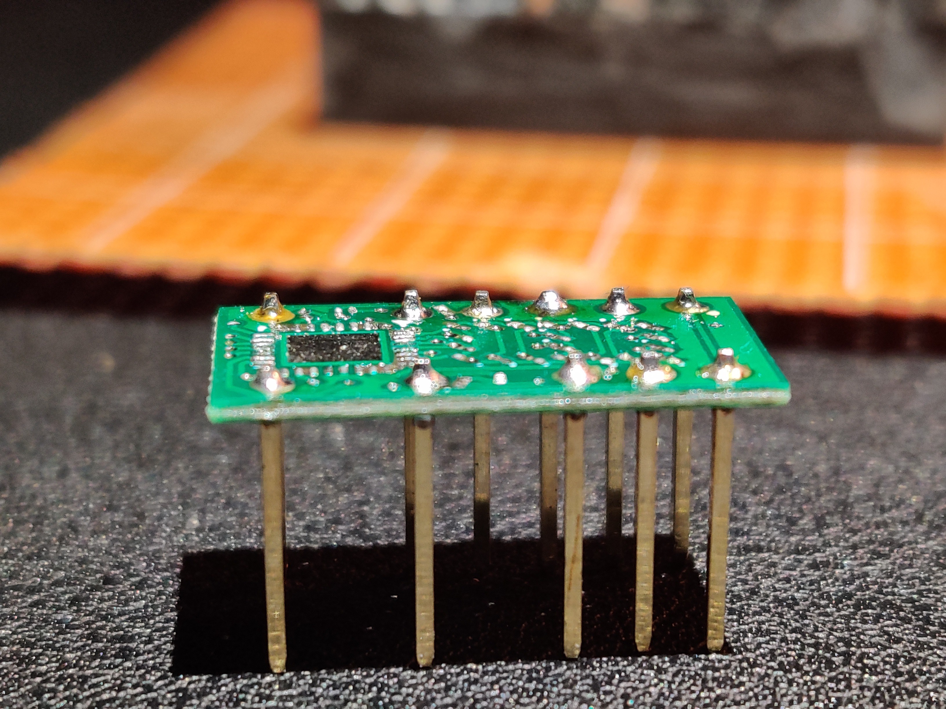
    The result is perfectly straight pins:

    ... Read more »

  • Design and Prototyping

    Jacob Still06/15/2019 at 07:07 0 comments

    Ok so this will be the first post of many. Keep in mind that this is a project in collaboration with a friend, so when I say "I", most of the time I mean "we".

    Anyways...

    The Original:

    This is a Texas Instruments TIL311. It takes a 4 bits (along with control lines + decimal points) and displays the data as it's hexadecimal representation. If you give it a 0000 it will display a 0 and 1111 will be an F. In addition to power and ground, the chip only uses 8 data lines (bits if you will) to function. This means that we only need a single byte to control the entire chip.

    TIL311
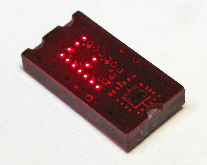
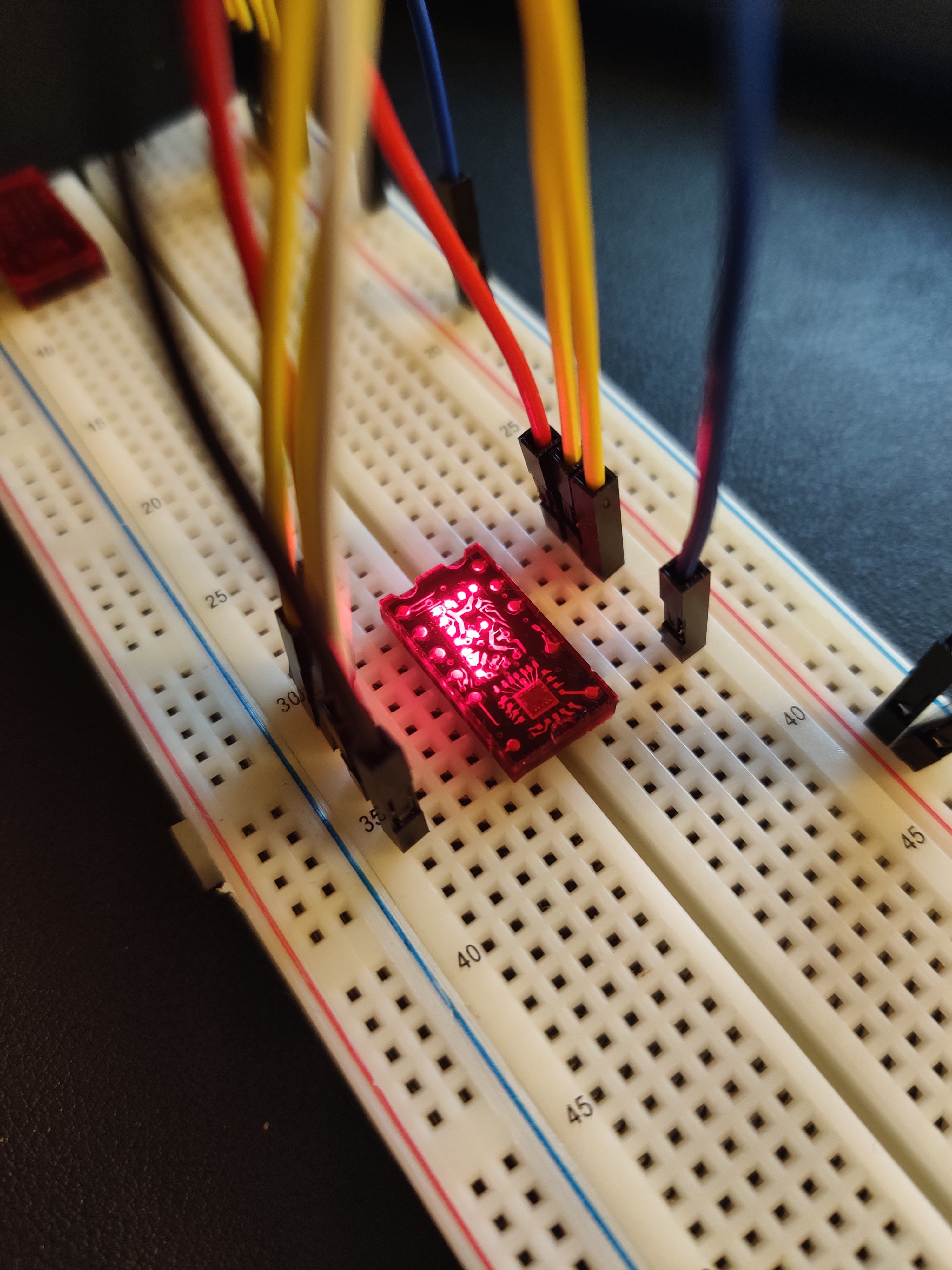
    my TIL311

    Parts:

    There are 22 LEDs under that red epoxy. In addition, there are 11 pins in a 14 pin DIP package. In order to take some binary data and display its representation in hex by turning on LEDs, we need a microcontroller. This is that square thing that is at the bottom of the chip (near row 35 on the breadboard). For simplicity's sake (or so I thought) we decided to multiplex the LEDs to use less pins on the microcontroller. So, our microcontroller needed to have 6 pins for data input (both the decimal points are independent of the control logic), and 11 output pins for the LED matrix (a 4X7 marix was used to make routing the board easier). Thats 17 pins to start, in addition we need 4 pins for programming (yes I could reuse the same pins but I decided not to) and 2 pins for an external oscillator. That's a total of 23 pins (plus VCC and GND).

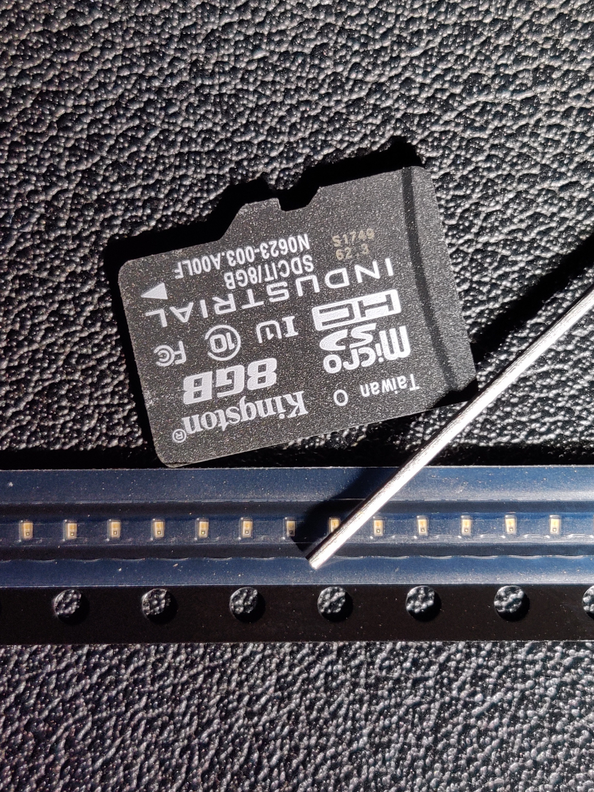
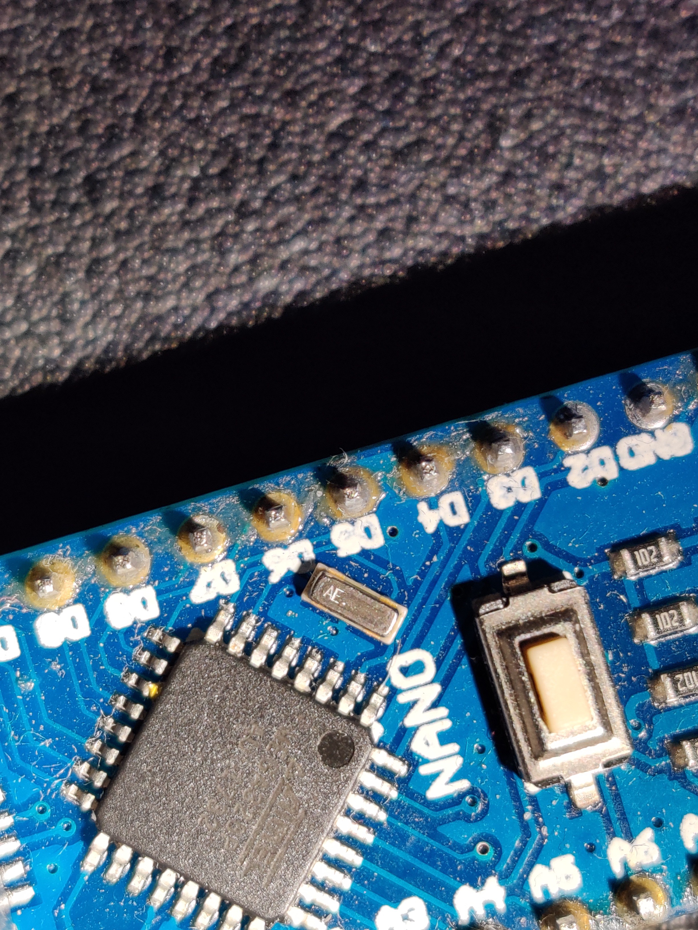
    We decided to go with the ATMEGA328P for this application as it comes in a VQFN package, has a whole lot of documentation as it is the main processor used on arduino boards, and is relatively cheap (I will not be using the arduino bootloader but that will be a future topic). The LEDs will be a 0201 package and will be orange (because I don't want to wait for a 10 week lead time or pay an extra like 5 cents per). There will be 0201 resistors and a 3 pin 16mhz ceramic resonator (similar to what arduino nanos have).

    The LEDs compared to a microSD card and 0.7mm pencil lead:

    The LEDs compared to a microSD card and 0.7mm pencil lead

    The resonator on a (knockoff) arduino nano:

    The resonator on a (knockoff) arduino nano

    Design:

    All schematics, pcb designs, and everything else will be in the files section (I may just put them on github if I run out of space here)

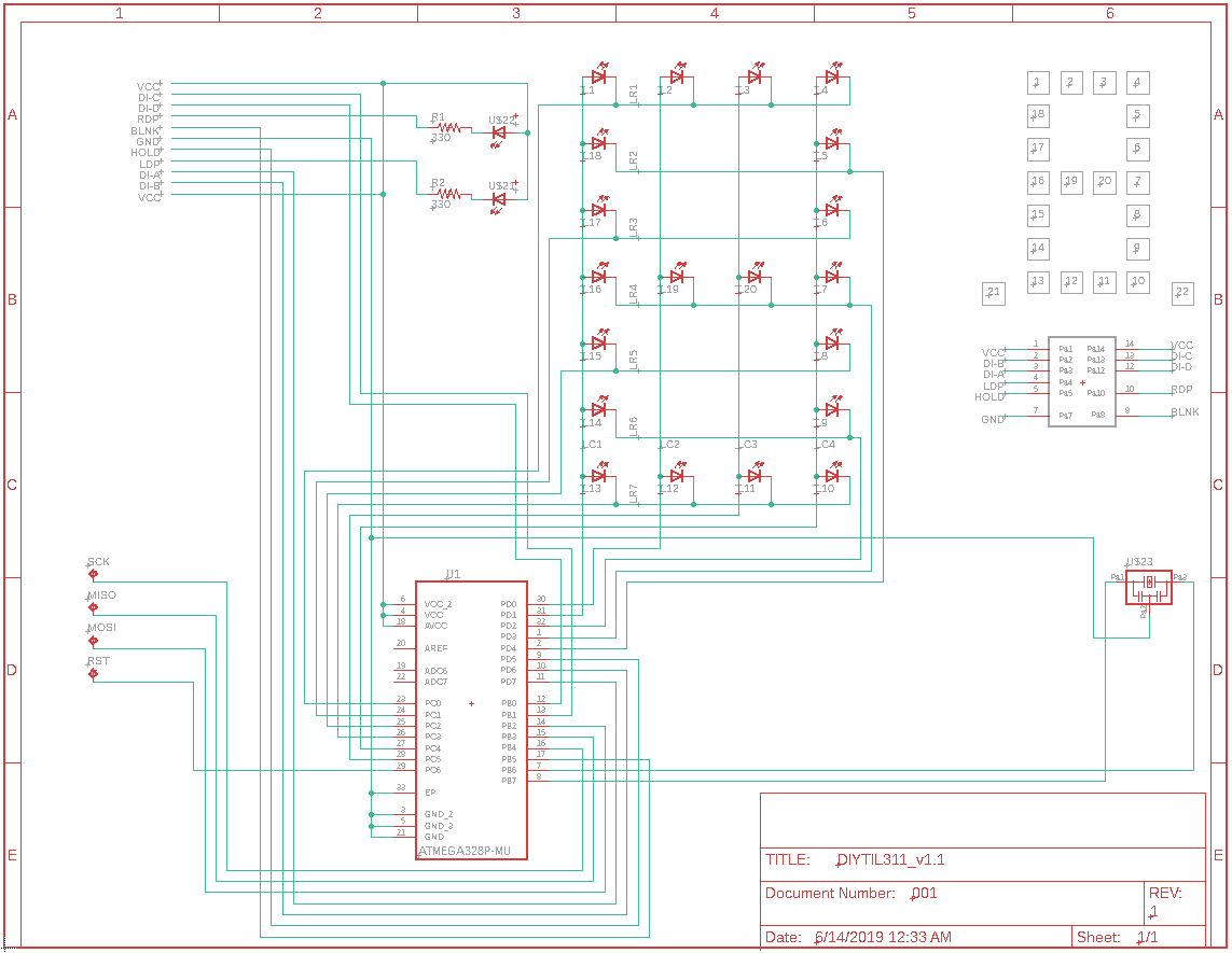
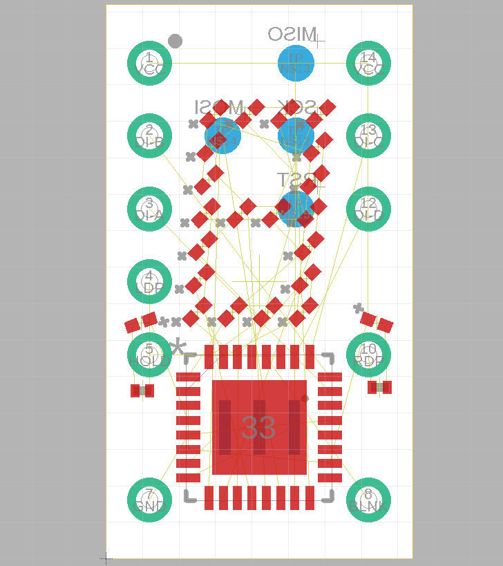
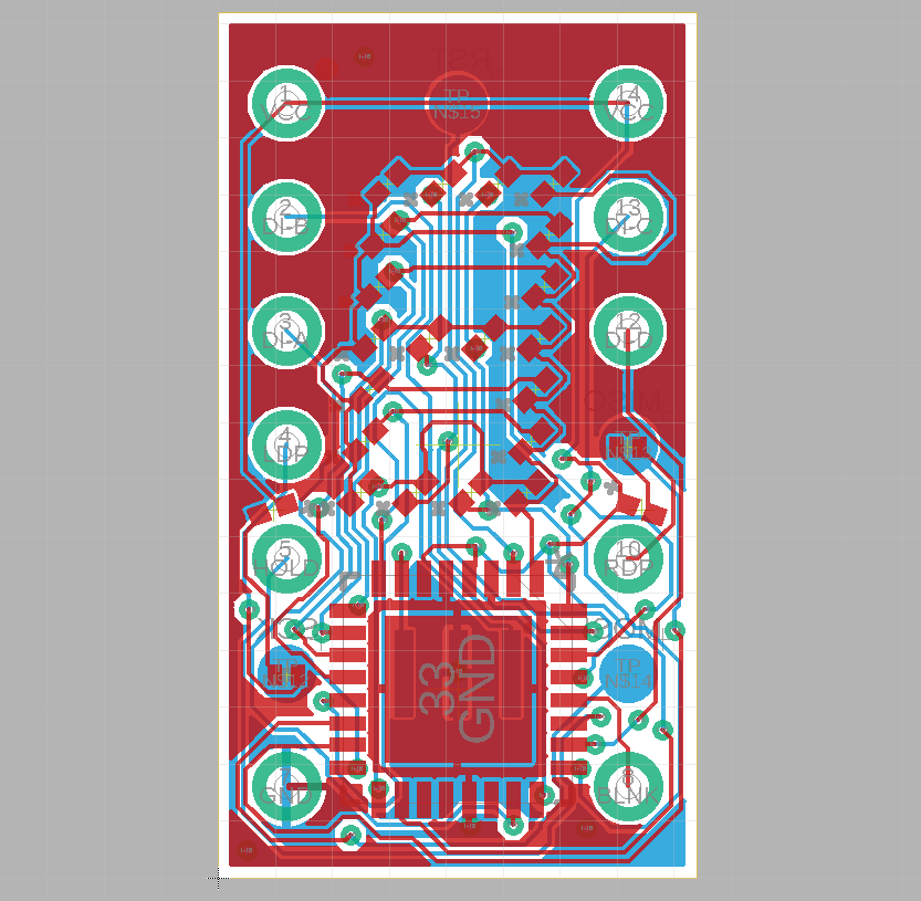
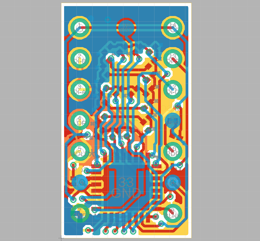
    After spending some time with the datasheets for the original TIL311 and the ATMEGA328P, I used Eagle to make a schematic and lay out all the components where I wanted them to be on the PCB. I then began the task of routing all the components according to the PCB manufacturer's specs. After 3 failed attempts to follow their specs (mainly because I am apparently an idiot that can't read) and about 2 weeks, I submitted the PCBs to be manufactured.

    Schematic:

    Schematic

    Failed PCB (I unrouted everything in hopes that I could salvage it but coudn't. sry that you dont get to see routes):

    Failed PCB (I unrouted everything in hopes that I could salvage it but coudn't. sry that you dont get to see routes)

    Failed PCB (tolerances too tight):

    Failed PCB (tolerances too tight)

    PCB that was accepted:

    PCB that was accepted

    In the next post I will go over how we plan on programming this thing as well as some other useful stuff.

View all 2 project logs

Enjoy this project?

Share

Discussions

Maximilian Laurenz wrote 07/05/2019 at 13:03 point

Love those retro display projects. Eagerly waiting for someone doing an affordable version of flip dots and nixie tubes. There are manufacturers (millclock.com, flipdots.com) but they're quite expensive.

  Are you sure? yes | no

jorgelestro wrote 07/04/2019 at 09:57 point

Great project idea!

  Are you sure? yes | no

Kevin wrote 07/04/2019 at 01:45 point

Nice project. I used a couple of TIL311's on an 1802 based computer board that I built almost 40 years ago. I still have 10 of them in one of my parts drawers which have never been used.

  Are you sure? yes | no

Jacob Still wrote 07/04/2019 at 05:34 point

Thats pretty cool, what did they display?

  Are you sure? yes | no

Kevin wrote 07/04/2019 at 16:36 point

The two TIL311's are used to display the bottom 8 bits of the address bus. There is a slide switch on the board that turns off the displays when they aren't needed. The displays are mainly used when entering a program in to memory. When in run mode the displays can be turned off.

  Are you sure? yes | no

Steve wrote 06/28/2019 at 12:23 point

This is awesome..  I remember in the 80s, my friend's dad had some of these that sometimes my friend could borrow and use in projects.. we thought they were the coolest displays, and yours is awesome!   My eyes could NEVER do that soldering or even component placement!  great job!!

  Are you sure? yes | no

Jacob Still wrote 06/28/2019 at 17:36 point

Thanks! I still am not quite sure how I'm going to pull this off...

  Are you sure? yes | no

Dillon Nichols wrote 06/28/2019 at 12:18 point

This is a great idea. I made a disintegrated LM3909 and was looking for other chips to recreate. I haven't thought of making old assemblies with discrete components. https://hackaday.io/project/29179-disintegrated-lm3909-15v-led-flasher

  Are you sure? yes | no

Jacob Still wrote 06/28/2019 at 17:42 point

That's cool! There are a ton of applications that would benefit from recreated components. Especially since the technology offered today is far more efficient.

  Are you sure? yes | no

Similar Projects

Does this project spark your interest?

Become a member to follow this project and never miss any updates