 Andy Geppert
The other circuit board and components did not show up this weekend, so I diverted to other important steps. That is, BOM refinement, assembly instructions, and mechanical design.
The first prototype design of the Core+LED Array holder is now in hand, ready for testing and design refinement.
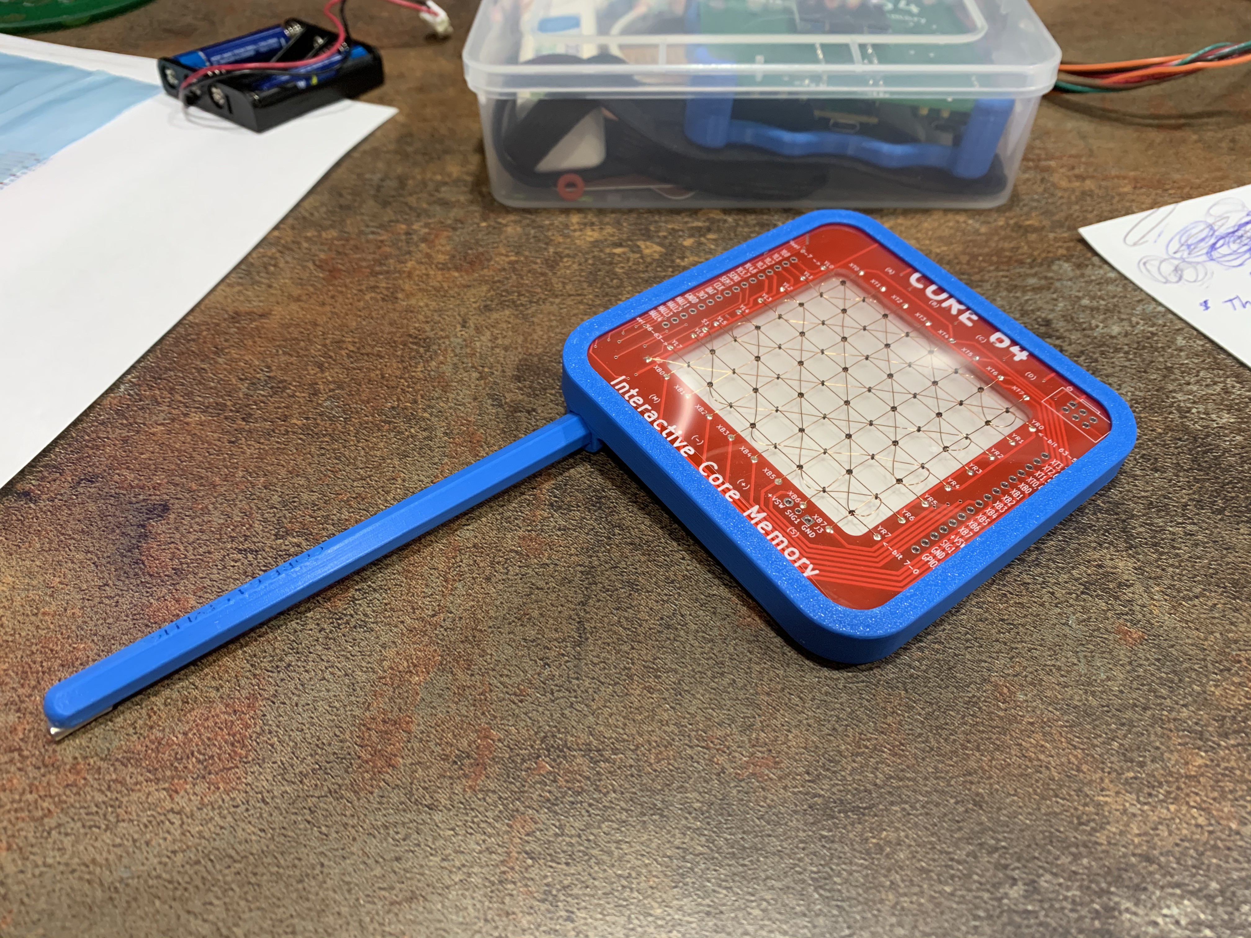
This is the direction I'm headed for a complete assembly:
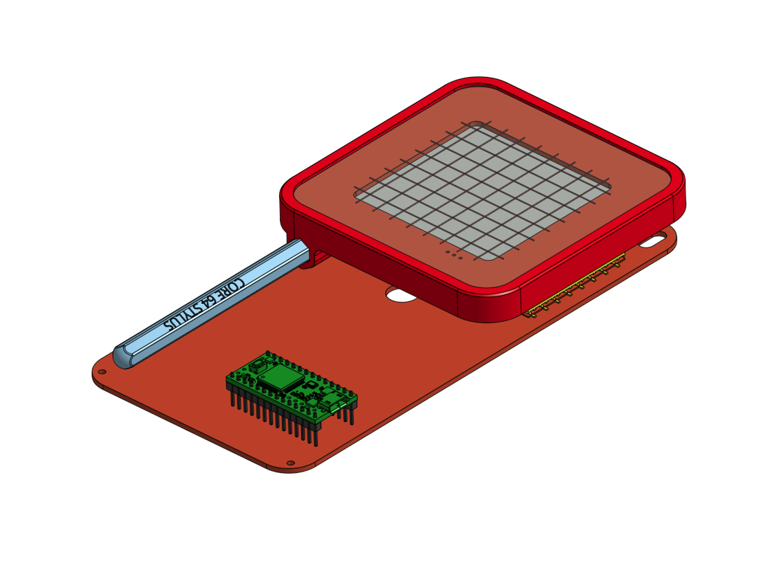
More refinement is needed, but just going through one cycle of the design/make process has already illuminated some breakthroughs in the assembly process for the LED Array holder. Even at this stage, I'm surprised how quickly everything comes together for a professional look thanks to quality 3D prints.
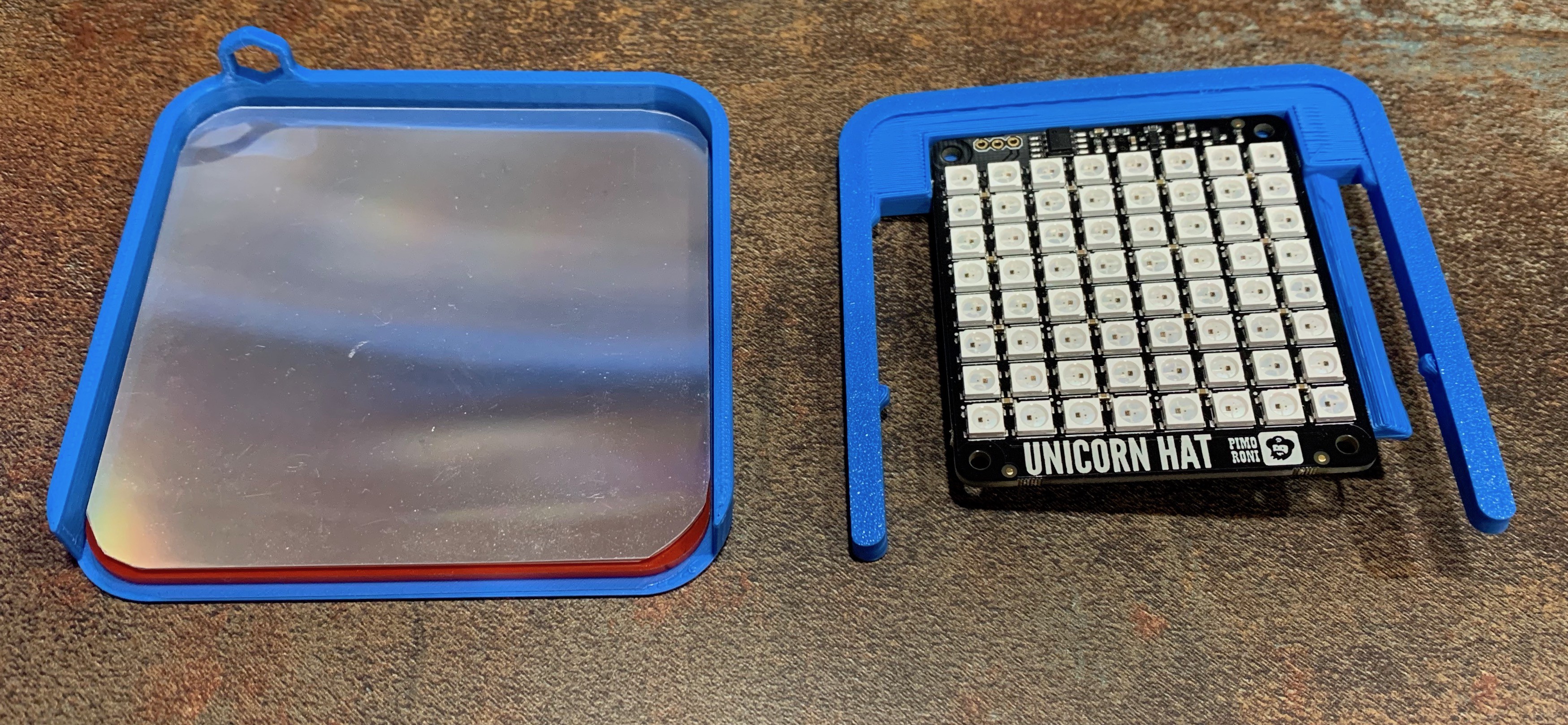
There is a screen protector layer over the cores (transparency film) and a diffuser layer (from a scrapped LCD panel) between the LEDs and the cores. And because printing this as one part creates a lot of support material (and removal work), I diverted to a two piece design, and now I don't need as many cut-outs, so that open gap on one end of the bezel will be completely filled in. Nice discovery to figure that out after I started printing the first one.
This project is quickly picking up steam again.
Discussions
Become a Hackaday.io Member
Create an account to leave a comment. Already have an account? Log In.