On the Arduino website you can download the software. If you don't have space on your device consider creating an account and using the Arduino Online Web Editor here. Either of these options will work fine. This will allow you to communicate with the Arduino to control the motors on the device.
2
Download "Nozzle" file to 3D print
In the files section you will find an STL file named Part11-Nozzle. Two of these need to be 3D printed to connect the plastic tubing to the chambers. Press here to download the file. Print two of this part as per the components list.
3
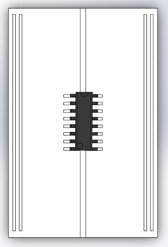
Attach H-Bridge
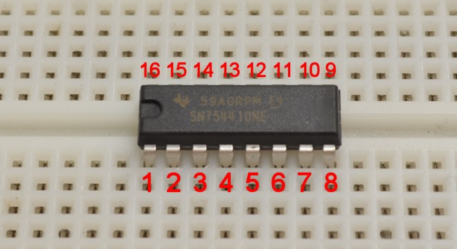
The H-bridge sends all the commands from the Arduino to the motors. It has 16 different terminals. Place the H-bridge in the middle of the breadboard so it "bridges" the two halves of the breadboard together. The half-circle cutout should face the top (not required, but makes it easier to remember which terminals are where!).
4
Ground the H-Bridge
With four short jumper cables connect terminals 4, 5, 12, 13 to the ground (-) bar on the breadboard.
5
Connecting the Arduino
Connect a jumper cable from the "5V" terminal on the Arduino to the positive (+) bar on the breadboard. Next connect another jumper cable from the "GND" terminal of the Arduino to the ground (-) of the breadboard. This will provide power to the positive bar of the breadboard. Lastly, connect a small jumper cable from the positive bar of the breadboard to terminal 16 of the H-bridge. This supplies power to the H-bridge.
6
Connecting breadboard power and ground
Connect a small jumper cable from the positive bar on the left of the breadboard to the one on the right. Now connect the left and right ground bars with another jumper cable. This makes one common ground and one common power supply throughout the breadboard.
7
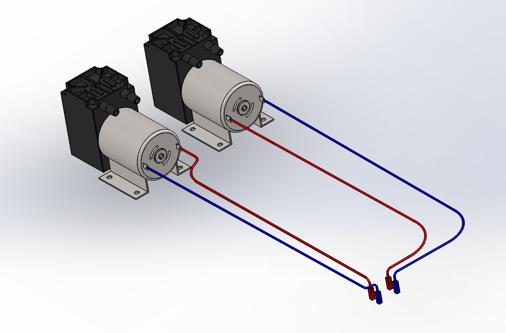
Soldering the motor terminals
Each motor has two terminals on it. Since you cannot plug in a jumper cable to these terminals I recommend soldering the four jumper cable ends (two for each motor) onto the four corresponding motor terminals. Strip one end of each jumper cable so there is about 1cm of exposed copper wire. Wrap the exposed wire around the motor terminal and solder it on however you like. After you've soldered the four jumper cables on you should have something like the image here.
8
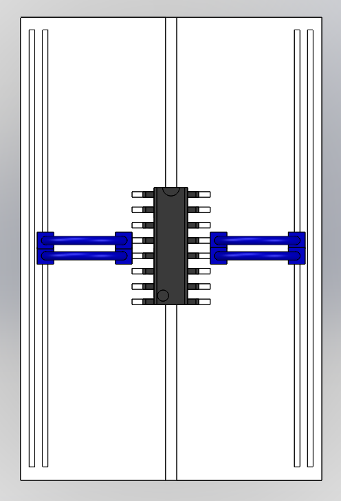
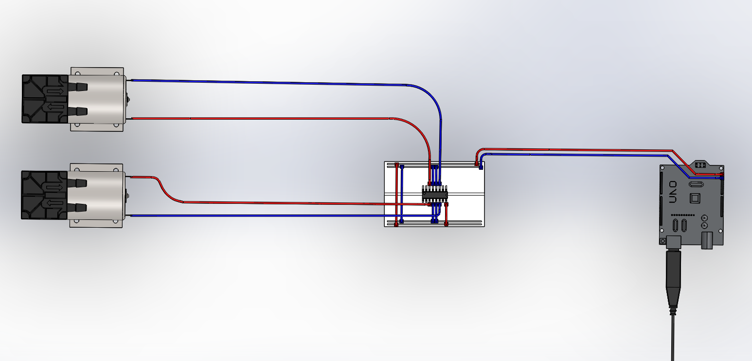
Connecting the motors
Each motor now has two jumper cables coming off of it. For motor one, connect those two cables to terminals 3 and 6 of the H-bridge. For motor two connect its' two cables to terminals 11 and 14. This supplies power to each of the motors. Here is an image of what you should have so far!
9
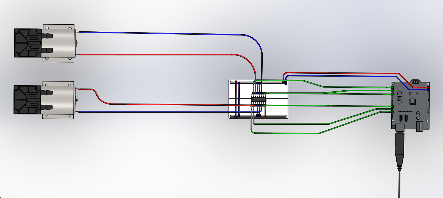
Controlling the motors
Now comes the trickiest part! Each motor will now have two pins called "logic pins". These tell the motors when to turn and which way to turn. Each motor will also have an additional logic pin that controls when power is supplied to the motor
For motor one, connect a jumper cable from Arduino terminal 4 to the H-bridge terminal 2. Then connect a second jumper cable from Arduino terminal 3 to H-bridge terminal 7. The additional logic pin requires a third jumper cable running from Arduino terminal 9 to H-bridge terminal 1.
For motor two, connect a jumper cable from Arduino terminal 7 to H-bridge terminal 10. Then connect a second jumper cable from Arduino terminal 6 to H-bridge terminal 15. The additional logic pin requires a third jumper cable running from Arduino terminal 12 to H-bridge terminal 9.
You should now have something that looks like the image below.
This may look cluttered so please refer to the systems' electrical layout to ensure you have connected everything correctly.
10
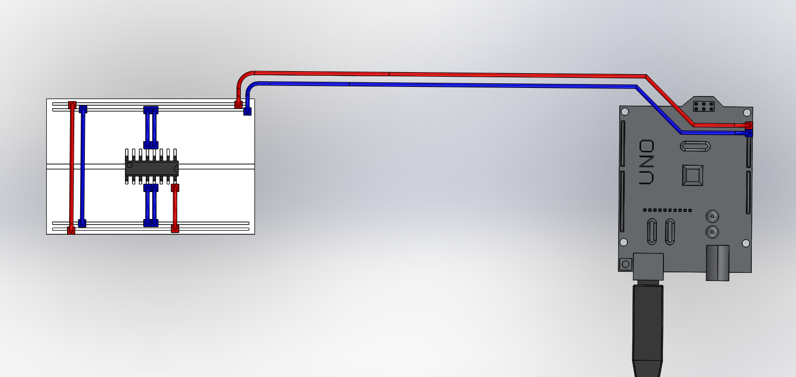
Powering the system
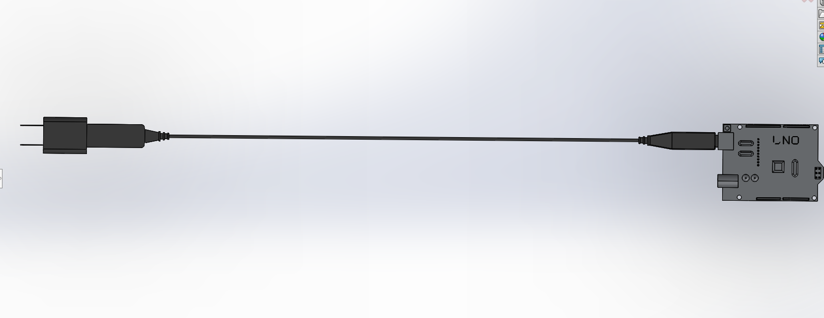
To send power to the Arduino you can just plug in the USB it comes with into a AC/DC converter (AKA a block).
To supply the motors with power you'll need an adjustable voltage supply from a wall socket. This gets plugged into a DC power jack. The DC power jack has two ports for jumper cables. Place and tighten a jumper cable into each of the ports. The cable in the positive port should go from the power jack to H-bridge terminal 8. The cable coming out of the negative (ground) port goes anywhere on the breadboards' ground bar. Here is a simplified image of the connection.
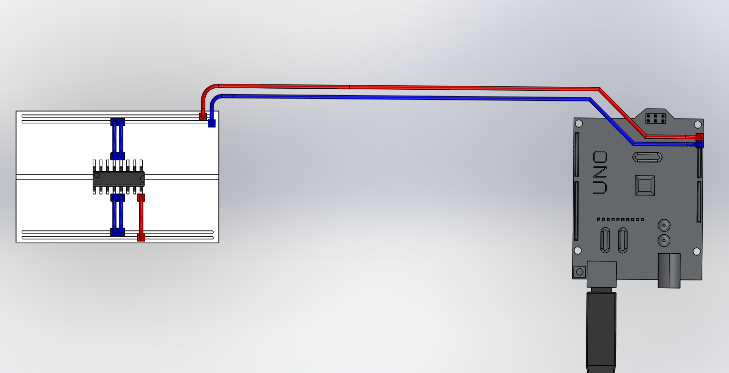
 To supply the motors with power you'll need an adjustable voltage supply from a wall socket. This gets plugged into a DC power jack. The DC power jack has two ports for jumper cables. Place and tighten a jumper cable into each of the ports. The cable in the positive port should go from the power jack to H-bridge terminal 8. The cable coming out of the negative (ground) port goes anywhere on the breadboards' ground bar. Here is a simplified image of the connection.
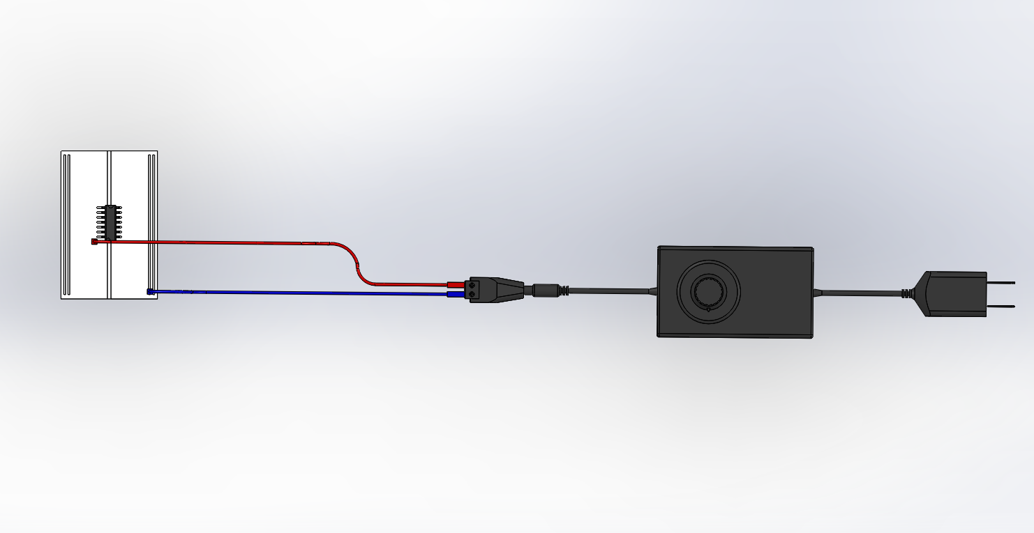
Discussions
Become a Hackaday.io Member
Create an account to leave a comment. Already have an account? Log In.