Close
0%
0%

Light Logic - Diode Resistor Logic out of its cage

Out of its cage and set free !

Similar projects worth following
Buffer, NOT, AND, NAND, OR, NOR, XOR and XNOR.

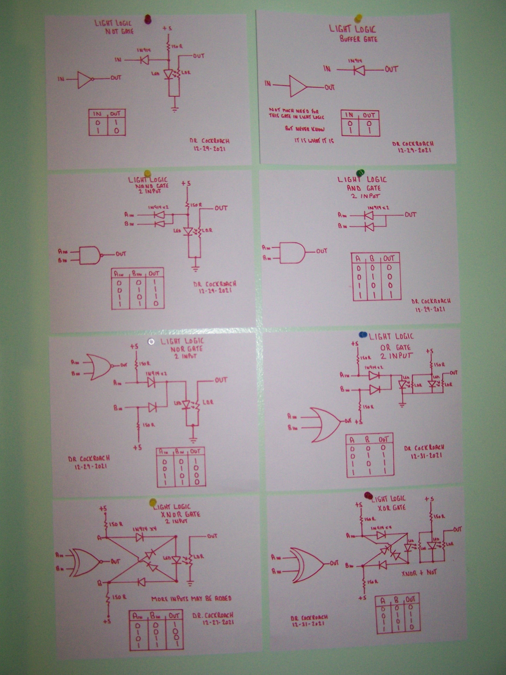
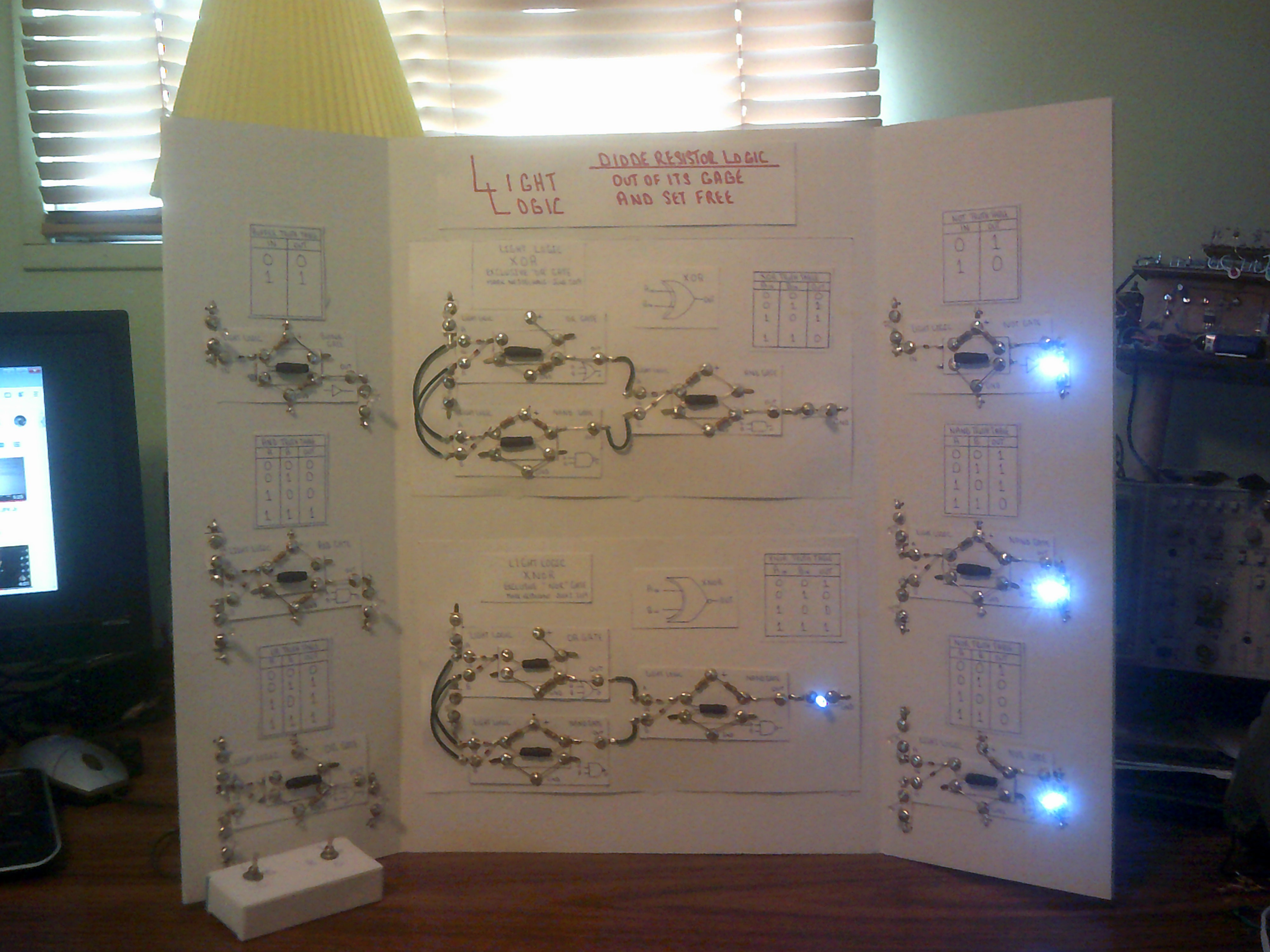
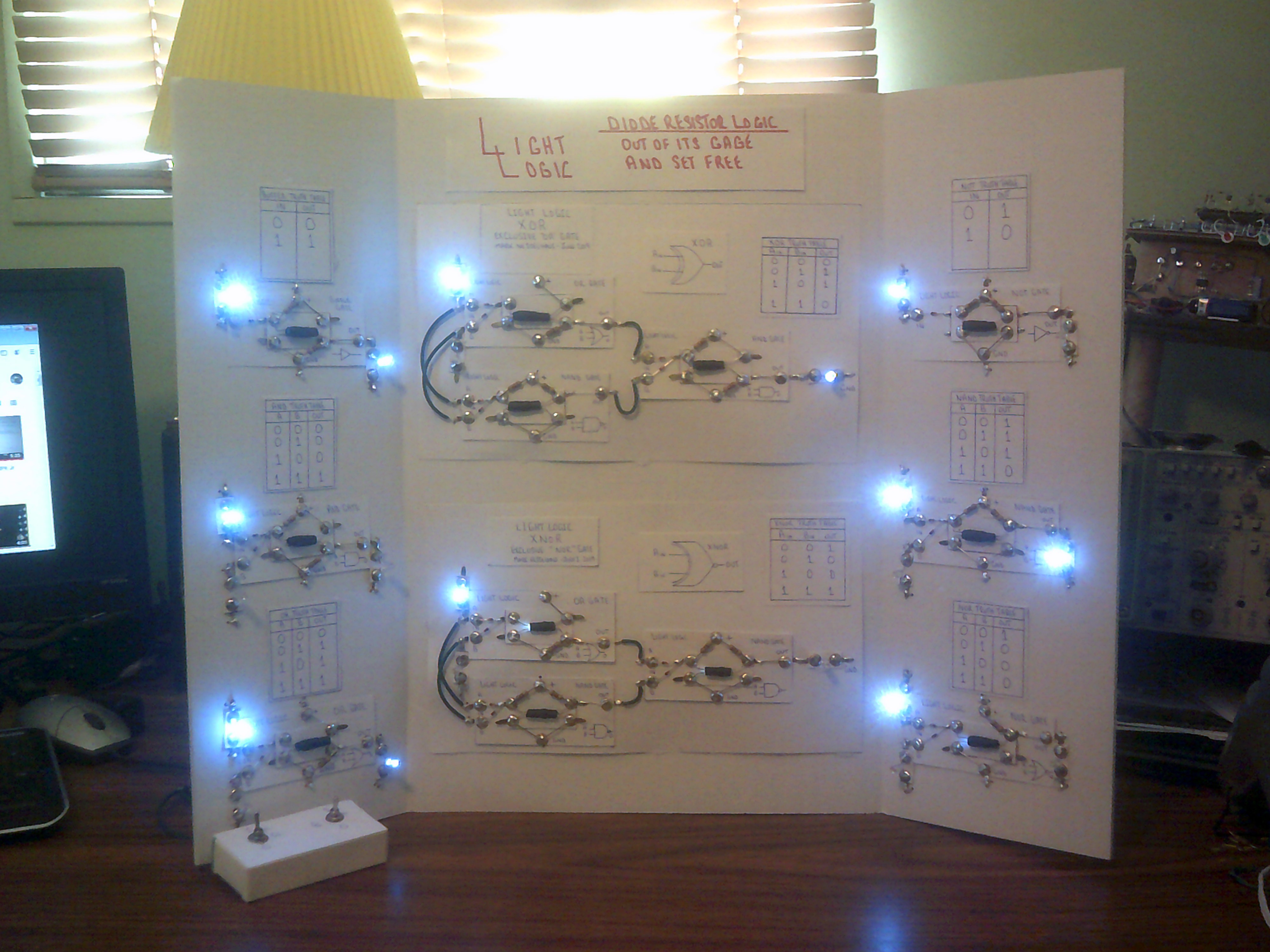
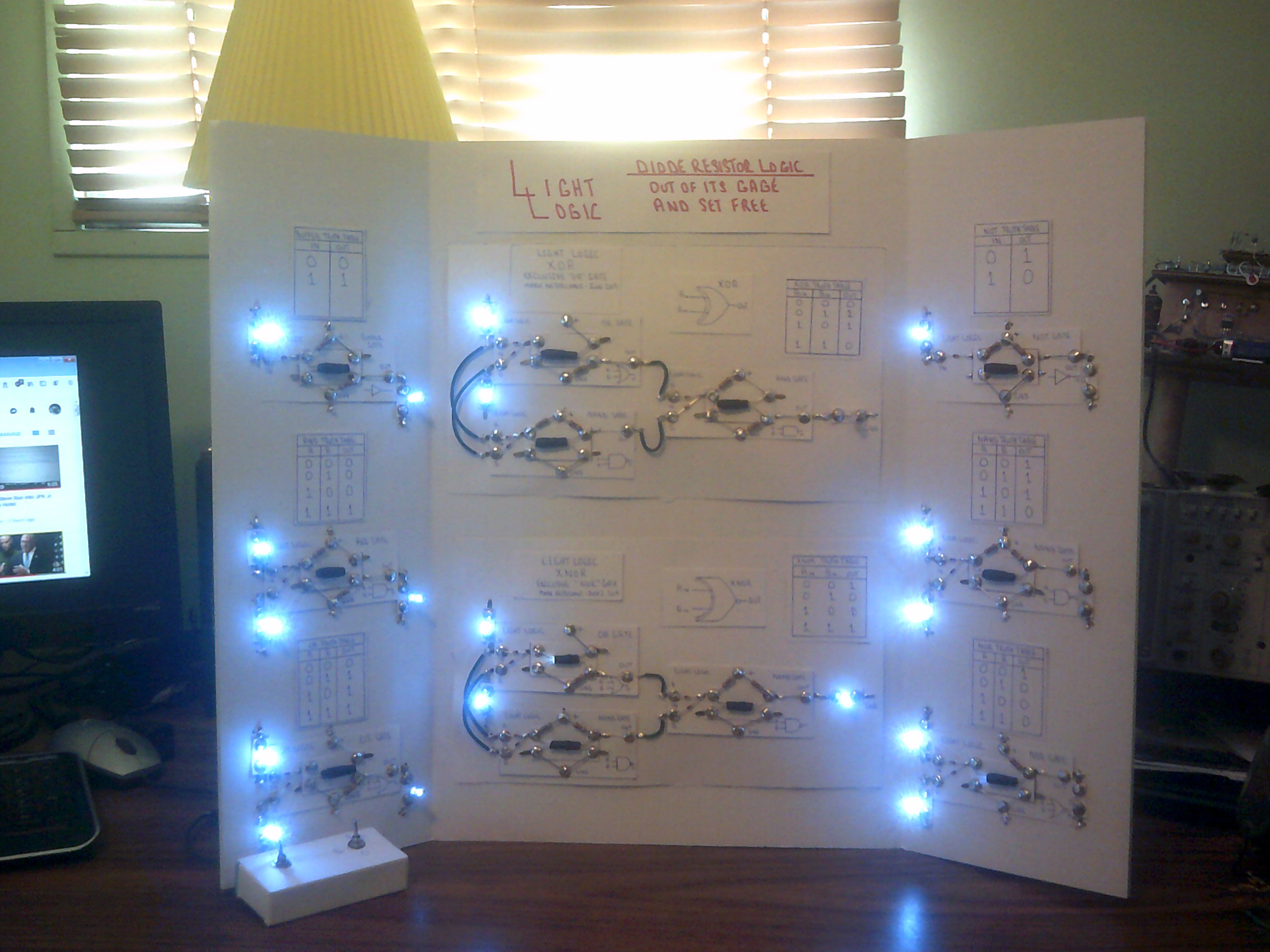
Diode logic is no longer restricted to AND and OR gates but can now perform ALL logic functions and with very few components. This project is to demonstrate the full logic range that Light Logic performs. For a back history and circuits of Light Logic, go to my other Light Logic project https://hackaday.io/project/161669-light-logic. All gates use only diodes and resistors. No transistors or relays to be found here.

To put it simply, the heart of any Light Logic gate is its Led and CdS photo resistor. This pair acts as a switch much as does a NPN transistor. Yes the CdS LDR does have a pronounced response curve to light but that's the fun in exploring how to work with that curve and overcome the drawbacks of circuit speed.

The whole point of Light Logic was to prove that DRL diode resistor logic was not restricted to AND and OR gate functions.

  • End of 2021 final Light Logic circuits

    Dr. Cockroach12/31/2021 at 23:55 0 comments

    December 31, 2021

    Not earth shattering but here are the final circuits for Light Logic. Happy New Year to everyone.

  • Improved XNOR gate

    Dr. Cockroach12/28/2021 at 14:10 2 comments

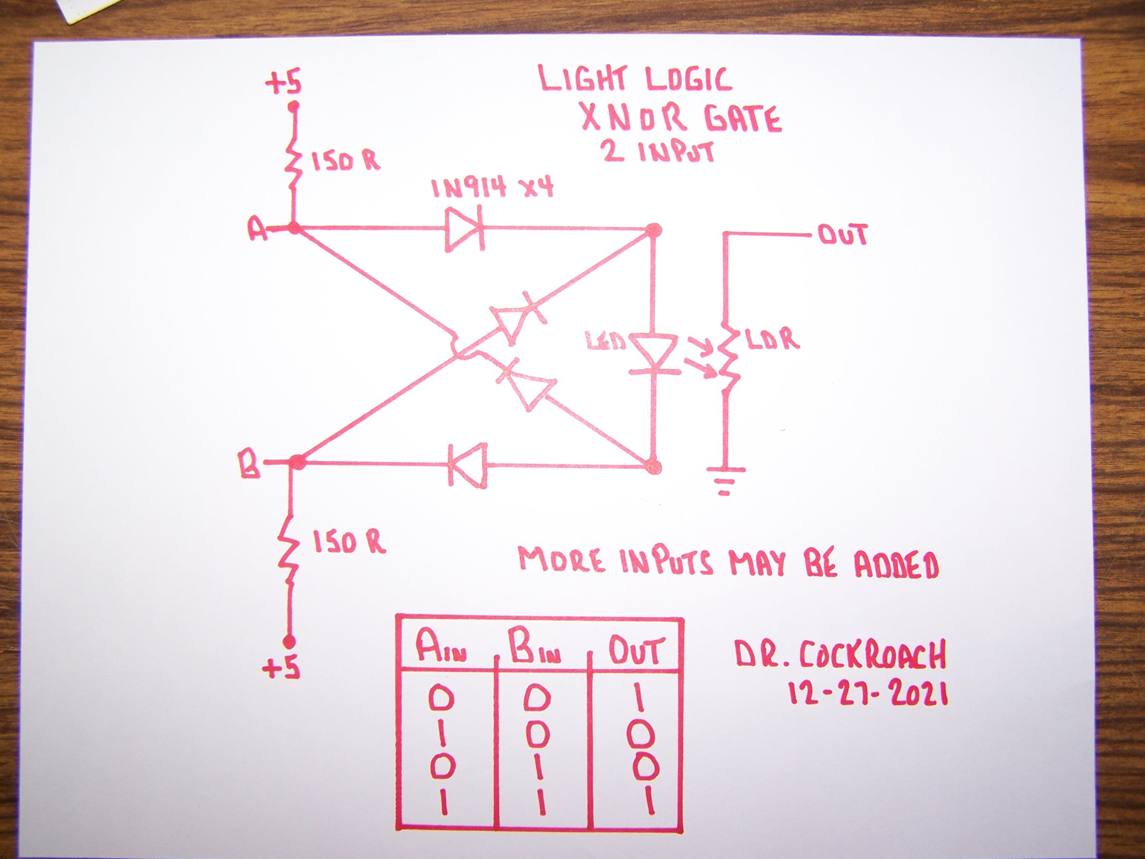
    December 28, 2021 - After a bit of an absence I started improving on some of my Light Logic gate circuits. I was never satisfied with how my XNOR gate turned out so I ended up having a dream last night and when I woke up this morning I got to working on what I had dreamed about. The simple change is that I now feed 5 volts to the inputs continuously through a pair of 150R resistors. If there is no input at either A or B then the input is considered HIGH. If either A or B is grounded through a previous gate then the input is LOW. The Out of the LDR can be followed by a Light Logic Inverter gate to create a XOR gate or wired to any other gate as needed. I have this circuit on a bread board and it is working as it should. Remember, with Light Logic  the output MUST be through the LDR to ground to be a counted as a solid Zero / Low. Anything else is counted as a One / High

  • Sequencer meets display

    Dr. Cockroach08/30/2019 at 00:32 0 comments

    This a great example of what diodes can do. The sequencer is just diodes, resistors and caps. The display and matrix from the IO project uses diodes only.

  • A Sequencer - The Next Addition

    Dr. Cockroach08/20/2019 at 18:58 0 comments

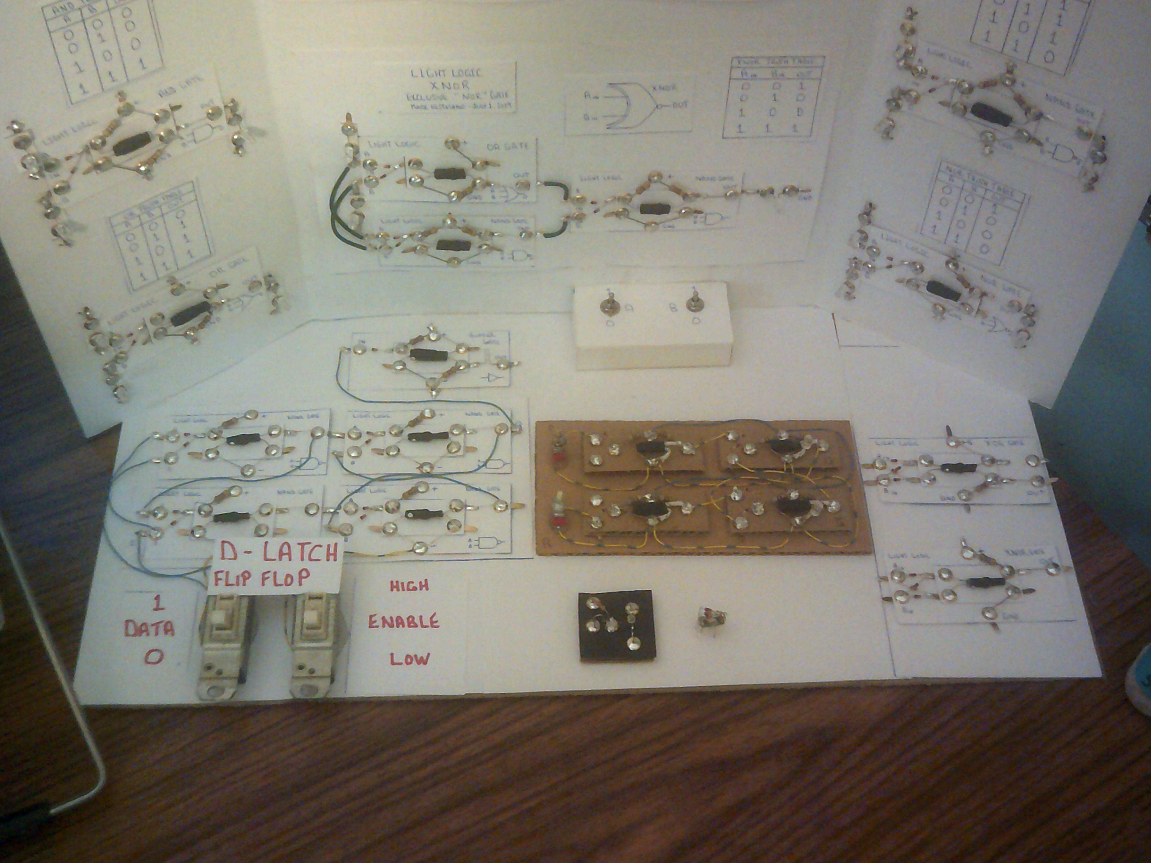
    I might as well add my seven step sequencer to the demo panel. This sequencer will find its way into my processor build this winter using only Light Logic circuits.

  • Adding more to the Educational Demo Panel

    Dr. Cockroach07/18/2019 at 23:31 0 comments

    I am planning to add other Light Logic circuits to the panel in order to showcase the progress of developing these logic circuits. I will add the original S-R Latch, a gate using a 0402 SMD Led, my smallest 3 input NAND gate constructed and of course the new XOR and XNOR single gate modules. There will be more to come.

  • A D-Latch added

    Dr. Cockroach07/14/2019 at 17:32 0 comments

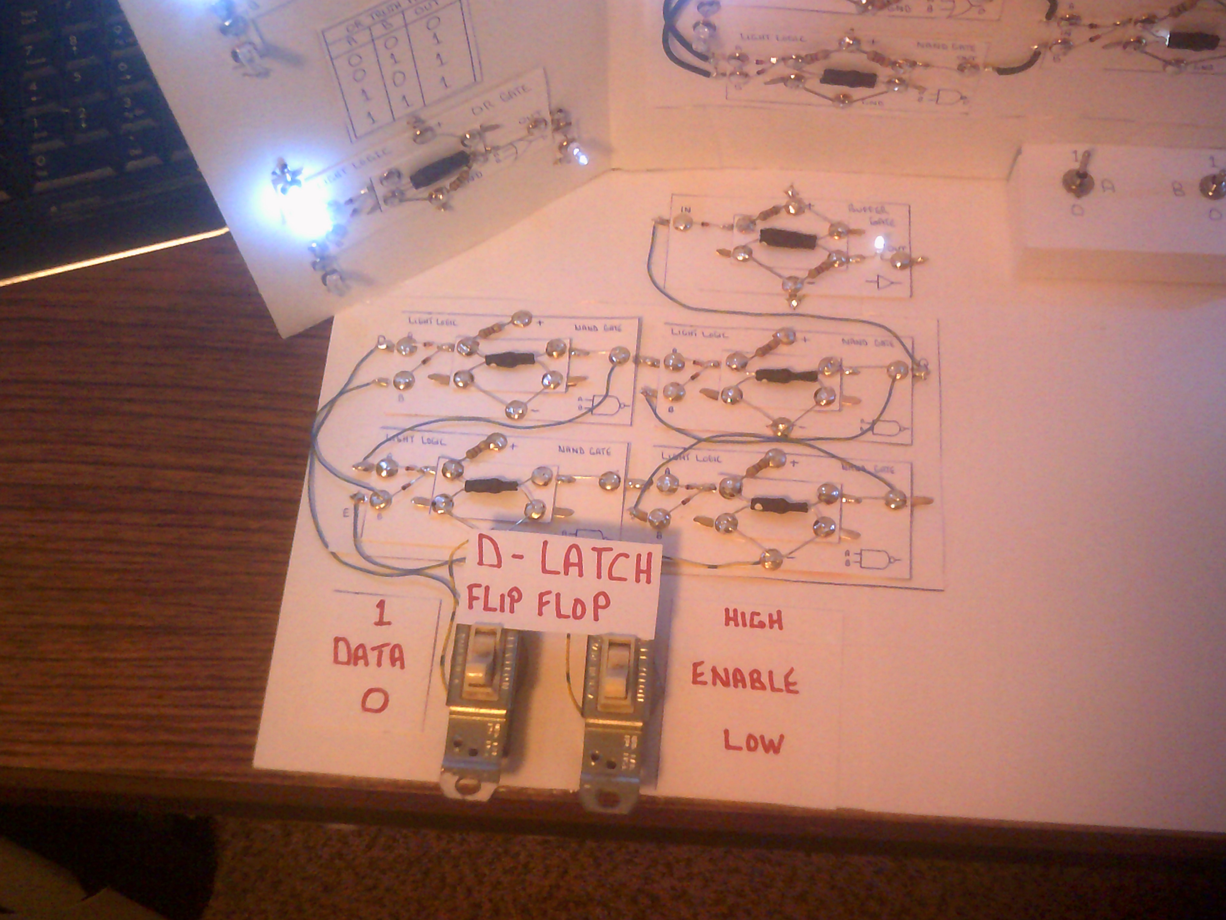
    The demo panel now sports a working D-Latch flip-flop that includes a led driver in the form of a Buffer gate on the Q output. You might notice that the NAND gates have had their CdS voltage supply resistors removed. These NAND gates as wired do not need a voltage to indicate a ONE output. Indeed the output can be a floating 0 volts and still count as a ONE unless the following gate is either a OR or NOR gate. It is the ground connection that makes a firm ZERO output do the job. That is why I am using a Buffer for the output Led indicator.

  • The truth of Light Logic

    Dr. Cockroach07/04/2019 at 15:31 0 comments

    Here are the four stages of Light Logic gate operation.

    Switch setting 0,0

    Switch setting 0,1

    Switch setting 1,0

    Switch setting 1,1

View all 7 project logs

Enjoy this project?

Share

Discussions

Similar Projects

Does this project spark your interest?

Become a member to follow this project and never miss any updates